


Copyright Notice:
No part of this installation guide may be reproduced, transcribed, transmitted, or translated in any language, in any form or by any means, except duplication of documentation by the purchaser for backup purpose, without written consent of ASRock Inc.
Products and corporate names appearing in this guide may or may not be registered trademarks or copyrights of their respective companies, and are used only for identification or explanation and to the owners’ benefit, without intent to infringe.
Disclaimer:
Specifications and information contained in this guide are furnished for informational use only and subject to change without notice, and should not be constructed as a commitment by ASRock. ASRock assumes no responsibility for any errors or omissions that may appear in this guide.
With respect to the contents of this guide, ASRock does not provide warranty of any kind, either expressed or implied, including but not limited to the implied warranties or conditions of merchantability or fitness for a particular purpose. In no event shall ASRock, its directors, officers, employees, or agents be liable for any indirect, special, incidental, or consequential damages (including damages for loss of profits, loss of business, loss of data, interruption of business and the like), even if ASRock has been advised of the possibility of such damages arising from any defect or error in the guide or product.
This device complies with Part 15 of the FCC Rules. Operation is subject to the following two conditions:
(1)this device may not cause harmful interference, and
(2)this device must accept any interference received, including interference that may cause undesired operation.
CALIFORNIA, USA ONLY
The Lithium battery adopted on this motherboard contains Perchlorate, a toxic substance controlled in Perchlorate Best Management Practices (BMP) regulations passed by the California Legislature. When you discard the Lithium battery in California, USA, please follow the related regulations in advance.
“Perchlorate Material-special handling may apply, see www.dtsc.ca.gov/hazardouswaste/perchlorate”
ASRock Website: http://www.asrock.com
Published July 2007
Copyright©2007 ASRock INC. All rights reserved.
1
English
ASRock 2Core1333-2.66G Motherboard

Motherboard Layout
English
2
1 |
PS2_USB_PWR1 Jumper |
15 |
Chassis Speaker Header (SPEAKER 1) |
2 |
ATX 12V Connector (ATX12V1) |
16 |
Chassis Fan Connector (CHA_FAN1) |
3 |
CPU Fan Connector (CPU_FAN1) |
17 |
USB 2.0 Header (USB6_7, Blue) |
4 |
775-Pin CPU Socket |
18 |
USB 2.0 Header (USB4_5, Blue) |
5 |
North Bridge Controller |
19 |
Floppy Connector (FLOPPY1) |
6 |
2 x 240-pin DDRII DIMM Slots |
20 |
HDMR Slot (HDMR1) |
|
(Dual Channel: DDRII_1, DDRII_2; Yellow) |
21 |
Front Panel Audio Header (HD_AUDIO1) |
7 |
IDE1 Connector (IDE1, Blue) |
22 |
PCI Slots (PCI1- 2) |
8 |
Clear CMOS Jumper (CLRCMOS1) |
23 |
Internal Audio Connector: CD1 (Black) |
9 |
South Bridge Controller |
24 |
PCI Express x1 Slot (PCIE2) |
10 |
Third SATAII Connector (SATAII_3; Orange) |
25 |
PCI Express x16 Slot (PCIE1) |
11 |
Fourth SATAII Connector (SATAII_4; Orange) |
26 |
ATX Power Connector (ATXPWR1) |
12 |
Secondary SATAII Connector (SATAII_2; Red) |
27 |
BIOS FWH Chip |
13 |
System Panel Header (PANEL1) |
28 |
Serial Port Connector (COM1) |
14 |
Primary SATAII Connector (SATAII_1; Red) |
29 |
Infrared Module Header (IR1) |
ASRock 2Core1333-2.66G Motherboard

HD 8CH I/O
1 |
Parallel Port |
8 |
Microphone (Pink) |
|
2 |
RJ-45 Port |
9 |
USB 2.0 |
Ports (USB01) |
3 |
Side Speaker (Gray) |
10 |
USB 2.0 |
Ports (USB23) |
4 |
Rear Speaker (Black) |
11 |
VGA Port |
|
5 |
Central / Bass (Orange) |
12 PS/2 Keyboard Port (Purple) |
||
6 |
Line In (Light Blue) |
13 |
PS/2 Mouse Port (Green) |
|
*7 Front Speaker (Lime)
*If you use 2-channel speaker, please connect the speaker’s plug into “Front Speaker Jack”. See the table below for connection details in accordance with the type of speaker you use.
TABLE for Audio Output Connection
Audio Output Channels |
Front Speaker |
Rear Speaker |
Central / Bass |
Side Speaker |
|
(No. 7) |
(No. 4) |
(No. 5) |
(No. 3) |
2 |
V |
-- |
-- |
-- |
4 |
V |
V |
-- |
-- |
6 |
V |
V |
V |
-- |
8 |
V |
V |
V |
V |
* To enable Multi-Streaming function, you need to connect a front panel audio cable to the front panel audio header. After restarting your computer, you will find “Mixer” tool on your system. Please select “Mixer ToolBox”  , click “Enable playback multi-streaming”, and click
“ok”. Choose “2CH”, “4CH”, “6CH”, or “8CH” and then you are allowed to select “Realtek HDA Primary output” to use Rear Speaker, Central/Bass, and Front Speaker, or select “Realtek HDA Audio 2nd output” to use front panel audio.
3
English
ASRock 2Core1333-2.66G Motherboard
1. Introduction
Thank you for purchasing ASRock 2Core1333-2.66G motherboard, a reliable motherboard produced under ASRock’s consistently stringent quality control. It delivers excellent performance with robust design conforming to ASRock’s commitment to quality and endurance.
This Quick Installation Guide contains introduction of the motherboard and step-by- step installation guide. More detailed information of the motherboard can be found in the user manual presented in the Support CD.
Because the motherboard specifications and the BIOS software might be updated, the content of this manual will be subject to change without notice. In case any modifications of this manual occur, the updated version will be available on ASRock website without further notice. You may find the latest VGA cards and CPU support lists on ASRock website as well.
ASRock website http://www.asrock.com
1.1 Package Contents
ASRock 2Core1333-2.66G Motherboard Bundled With Selected Dual Core CPU
Operating at FSB1333 / 2.66GHz
(Micro ATX Form Factor: 9.6-in x 9.0-in, 24.4 cm x 22.9 cm) ASRock 2Core1333-2.66G Quick Installation Guide
ASRock 2Core1333-2.66G Support CD
One 80-conductor Ultra ATA 66/100 IDE Ribbon Cable One Ribbon Cable for a 3.5-in Floppy Drive
One Serial ATA (SATA) Data Cable (Optional)
One Serial ATA (SATA) HDD Power Cable (Optional) One HD 8CH I/O Shield
One COM Port Bracket
English
4
ASRock 2Core1333-2.66G Motherboard

1.2Specifications
|
Platform |
- Micro ATX Form Factor: 9.6-in x 9.0-in, 24.4 cm x 22.9 cm |
|
CPU |
- Bundle with selected Dual Core CPU operating at |
|
|
FSB1333 / 2.66GHz |
|
|
* This motherboard also supports below CPU specifications: |
|
|
- LGA 775 for Intel® Dual Core CoreTM 2 Extreme / CoreTM 2 Duo |
|
|
/ Pentium® D / Pentium® Dual Core / Pentium® 4 / Celeron® / |
|
|
Celeron® D |
|
|
- Compatible with all FSB1333/1066/800/533MHz CPUs except Quad |
|
|
Core (see CAUTION 1) |
|
|
- Supports Hyper-Threading Technology |
|
|
- Supports Untied Overclocking Technology (see CAUTION 2) |
|
|
- Supports EM64T CPU |
|
Chipset |
- Northbridge: Intel® 945GC A2 |
|
|
- Southbridge: Intel® ICH7 |
|
Memory |
- Dual Channel DDRII Memory Technology (see CAUTION 3) |
|
|
- 2 x DDRII DIMM slots |
|
|
- Support DDRII667/533 (see CAUTION 4) |
|
|
- Max. capacity: 4GB (see CAUTION 5) |
|
Hybrid Booster |
- CPU Frequency Stepless Control (see CAUTION 6) |
|
|
- ASRock U-COP (see CAUTION 7) |
|
|
- Boot Failure Guard (B.F.G.) |
|
Expansion Slot |
- 1 x PCI Express x16 slot |
|
|
- 1 x PCI Express x1 slot |
|
|
- 2 x PCI slots |
|
|
- 1 x HDMR slot |
|
Graphics |
- Intel® Graphics Media Accelerator 950 |
|
|
- Pixel Shader 2.0, DirectX 9.0 |
|
|
- Max. shared memory 224MB (see CAUTION 8) |
|
|
|
|
Audio |
- 7.1 CH Windows® VistaTM Premium Level HD Audio |
|
|
(ALC888 Audio Codec) |
|
|
|
|
LAN |
- Realtek PCIE x1 LAN 8101E |
|
|
- Speed: 10/100 Ethernet |
|
|
- Supports Wake-On-LAN |
|
|
|
|
Rear Panel I/O |
HD 8CH I/O |
|
|
- 1 x PS/2 Mouse Port |
|
|
- 1 x PS/2 Keyboard Port |
|
|
- 1 x VGA Port |
|
|
- 1 x Parallel Port (ECP/EPP Support) |
|
|
- 4 x Ready-to-Use USB 2.0 Ports |
|
|
- 1 x RJ-45 LAN Port |
English
5
ASRock 2Core1333-2.66G Motherboard

English
6
|
- HD Audio Jack: Side Speaker/Rear Speaker/Central/Bass/ |
|
Line in/Front Speaker/Microphone (see CAUTION 9) |
Connector |
- 4 x SATAII 3.0 Gb/s connectors (No Support for RAID and |
|
“Hot Plug” functions) (see CAUTION 10) |
|
- 1 x ATA100 IDE connector (supports 2 x IDE devices) |
|
- 1 x Floppy connector |
|
- 1 x IR header |
|
- 1 x COM port header |
|
- CPU/Chassis FAN connector |
|
- 20 pin ATX power connector |
|
- 4 pin 12V power connector |
|
- CD in header |
|
- Front panel audio connector |
|
- 2 x USB 2.0 headers (support 4 USB 2.0 ports) |
|
(see CAUTION 11) |
BIOS Feature |
- 4Mb AMI BIOS |
|
- AMI Legal BIOS |
|
- Supports “Plug and Play” |
|
- ACPI 1.1 Compliance Wake Up Events |
|
- Supports jumperfree |
|
- AMBIOS 2.3.1 Support |
Support CD |
- Drivers, Utilities, AntiVirus Software (Trial Version) |
Hardware |
- CPU Temperature Sensing |
Monitor |
- Chassis Temperature Sensing |
|
- CPU Fan Tachometer |
|
- Chassis Fan Tachometer |
|
- CPU Quiet Fan |
|
- Voltage Monitoring: +12V, +5V, +3.3V, Vcore |
OS |
- Microsoft® Windows® 2000/XP/XP 64-bit/VistaTM/ |
|
VistaTM 64-bit compliant (see CAUTION 12) |
Certifications |
- FCC, CE, WHQL |
WARNING
Please realize that there is a certain risk involved with overclocking, including adjusting the setting in the BIOS, applying Untied Overclocking Technology, or using the thirdparty overclocking tools. Overclocking may affect your system stability, or even cause damage to the components and devices of your system. It should be done at your own risk and expense. We are not responsible for possible damage caused by overclocking.
ASRock 2Core1333-2.66G Motherboard

CAUTION!
1. FSB1333-CPU will operate in overclocking mode. Under this situation, PCIE frequency will also be overclocked to 115MHz.
2. This motherboard supports Untied Overclocking Technology. Please read
|
“Untied Overclocking Technology” on page 20 for details. |
||
3. |
This motherboard supports Dual Channel Memory Technology. Before you |
||
|
implement Dual Channel Memory Technology, make sure to read the |
||
|
installation guide of memory modules on page 12 for proper installation. |
||
4. |
Please check the table below for the CPU FSB frequency and its corre- |
||
|
sponding memory support frequency. |
||
|
CPU FSB Frequency |
Memory Support Frequency |
|
|
1333 |
DDRII533*, DDRII667 |
|
|
1066 |
DDRII533, DDRII667 |
|
|
800 |
DDRII400, DDRII533, DDRII667 |
|
|
533 |
DDRII400, DDRII533 |
|
|
* When you use a FSB1333-CPU on this motherboard, it will run at |
||
|
DDRII500 if you adopt a DDRII533 memory module. |
||
5. |
Due to the chipset limitation, the actual memory size may be less than |
||
|
4GB for the reservation for system usage under Windows® XP, Windows® |
||
|
XP 64-bit, Windows® VistaTM and Windows® VistaTM 64-bit. |
||
6. |
Although this motherboard offers stepless control, it is not recommended |
||
|
to perform over-clocking. Frequencies other than the recommended CPU |
||
|
bus frequencies may cause the instability of the system or damage the |
||
|
CPU. |
|
|
7. |
While CPU overheat is detected, the system will automatically shutdown. |
||
|
Before you resume the system, please check if the CPU fan on the |
||
|
motherboard functions properly and unplug the power cord, then plug it |
||
|
back again. To improve heat dissipation, remember to spray thermal |
||
|
grease between the CPU and the heatsink when you install the PC system. |
||
8. |
The maximum shared memory size is defined by the chipset vendor and |
||
|
is subject to change. Please check Intel® website for the latest information. |
||
9. |
For microphone input, this motherboard supports both stereo and mono |
||
|
modes. For audio output, this motherboard supports 2-channel, 4-channel, |
||
|
6-channel, and 8-channel modes. Please check the table on page 3 for |
||
|
proper connection. |
|
|
10. Before installing SATAII hard disk to SATAII connector, please read the “SATAII Hard Disk Setup Guide” on page 19 to adjust your SATAII hard disk drive to SATAII mode. You can also connect SATA hard disk to SATAII connector directly.
11. Power Management for USB 2.0 works fine under Microsoft® Windows® VistaTM 64-bit / VistaTM / XP 64-bit / XP SP1 or SP2 / 2000 SP4.
12. Microsoft® Windows® VistaTM / VistaTM 64-bit driver keeps on updating now. As long as we have the latest driver, we will update it to our website in the future. Please visit our website for Microsoft® Windows® VistaTM / VistaTM 64-bit driver and related information.
ASRock website http://www.asrock.com
English
7
ASRock 2Core1333-2.66G Motherboard

1.3Minimum Hardware Requirement Table for Windows®
VistaTM Premium 2007 and Basic Logo
For system integrators and users who purchase this motherboard and plan to submit Windows® VistaTM Premium 2007 and Basic logo, please follow below table for minimum hardware requirements.
Memory |
512MB x 2 Dual Channel (Premium) |
|
512MB Single Channel (Basic) |
|
256MB x 2 Dual Channel (Basic) |
VGA |
DX9.0 with WDDM Driver |
*If you plan to use onboard VGA to submit Windows® VistaTM logo, please keep the default setting of “DVMT Mode Select” option under BIOS.
*If you plan to use external graphics card on this motherboard, please refer to Premium Discrete requirement at http://www.asrock.com
*After June 1, 2007, all Windows® VistaTM systems are required to meet above minimum hardware requirements in order to qualify for Windows® VistaTM Premium 2007 logo.
English
8
ASRock 2Core1333-2.66G Motherboard

2. Installation
Pre-installation Precautions
Take note of the following precautions before you install motherboard components or change any motherboard settings.
1.Unplug the power cord from the wall socket before touching any component. Failure to do so may cause severe damage to the motherboard, peripherals, and/or components.
2.To avoid damaging the motherboard components due to static electricity, NEVER place your motherboard directly on the carpet or the like. Also remember to use a grounded wrist strap or touch a safety grounded object before you handle components.
3.Hold components by the edges and do not touch the ICs.
4.Whenever you uninstall any component, place it on a grounded antstatic pad or in the bag that comes with the component.
5.When placing screws into the screw holes to secure the motherboard to the chassis, please do not over-tighten the screws! Doing so may damage the motherboard.
2.1CPU Installation
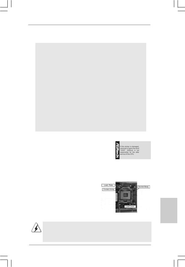
This motherboard is bundled with one selected Dual Core CPU operating at FSB1333 / 2.66GHz. Please do not remove ASRock CPU stickers on both sides of CPU socket on this motherboard. If the stickers are damaged, removed or bear the word “VOID”, ASRock is not responsible for the after service of this CPU.
In the future, you may adopt other compatible Intel 775-LAND CPU on this motherboard. For the installation of Intel 775-
LAND CPU, please follow the steps below. ASRock reminds you that as long as you adopt other CPU on this motherboard, we will not be responsible for the after service of the bundled CPU.
ASRock CPU Sticker
775-Pin Socket Overview
Before you insert the 775-LAND CPU into the socket, please check if the CPU surface is unclean or if there is any bent pin on the socket. Do not force to insert the CPU into the socket if above situation is
found. Otherwise, the CPU will be seriously damaged.
9
English
ASRock 2Core1333-2.66G Motherboard
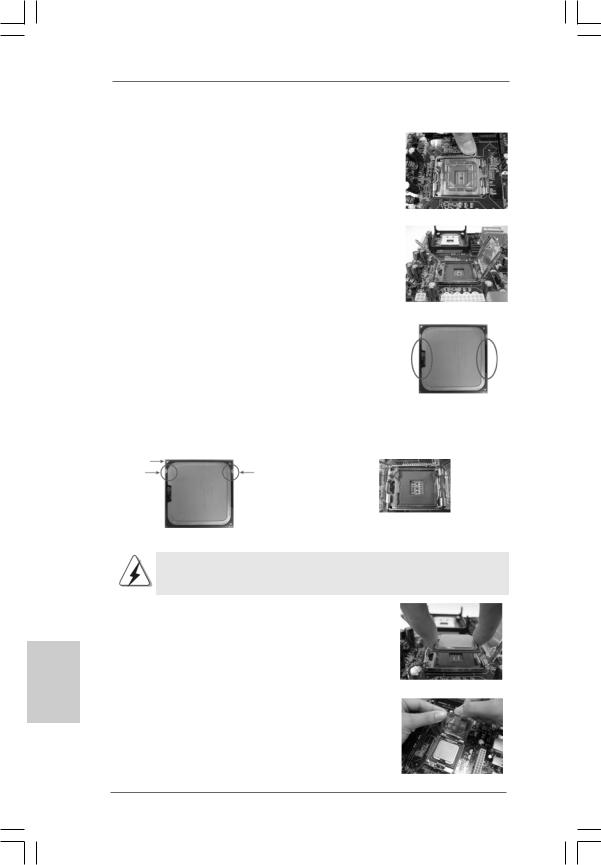
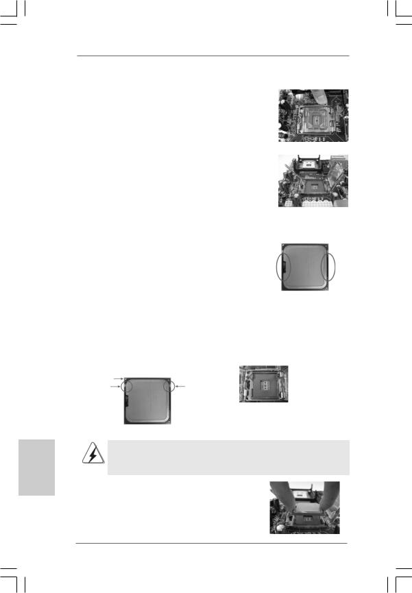
Step 1. Open the socket:
Step 1-1. Disengaging the lever by depressing down and out on the hook to clear retention tab.
English
Step 1-2. Rotate the load lever to fully open position at approximately 135 degrees.
Step 1-3. Rotate the load plate to fully open position at approximately 100 degrees.
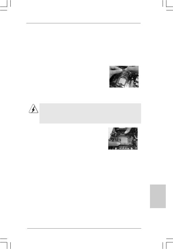
Step 2. Insert the 775-LAND CPU:
Step 2-1. Hold the CPU by the edges where are marked with black lines.
Step 2-2. Orient the CPU with IHS (Integrated Heat Sink) up. Locate Pin1 and the two orientation key notches.
lineblack |
lineblack |
Pin1 |
|
Pin1 |
|
|
|
alignment key |
|
orientation |
orientation |
alignment key |
|
|
|
||
key notch |
key notch |
|
|
|
|
|
775-Pin Socket |
|
775-LAND CPU |
|
|
For proper inserting, please ensure to match the two orientation key notches of the CPU with the two alignment keys of the socket.
Step 2-3. Carefully place the CPU into the socket by using a purely vertical motion.
Step 2-4. Verify that the CPU is within the socket and properly mated to the orient keys.
Step 3. Remove PnP Cap (Pick and Place Cap):
Use your left hand index finger and thumb to support the load plate edge, engage PnP cap with right hand thumb and peel the cap from the socket while pressing on center of PnP cap to assist in removal.
1 0
ASRock 2Core1333-2.66G Motherboard
1.It is recommended to use the cap tab to handle and avoid kicking off the PnP cap.
2.This cap must be placed if returning the motherboard for after service.
Step 4. Close the socket:
Step 4-1. Rotate the load plate onto the IHS. Step 4-2. While pressing down lightly on load
plate, engage the load lever.
Step 4-3. Secure load lever with load plate tab under retention tab of load lever.
2.2Installation of CPU Fan and Heatsink
For proper installation, please kindly refer to the instruction manuals of your CPU fan and heatsink.
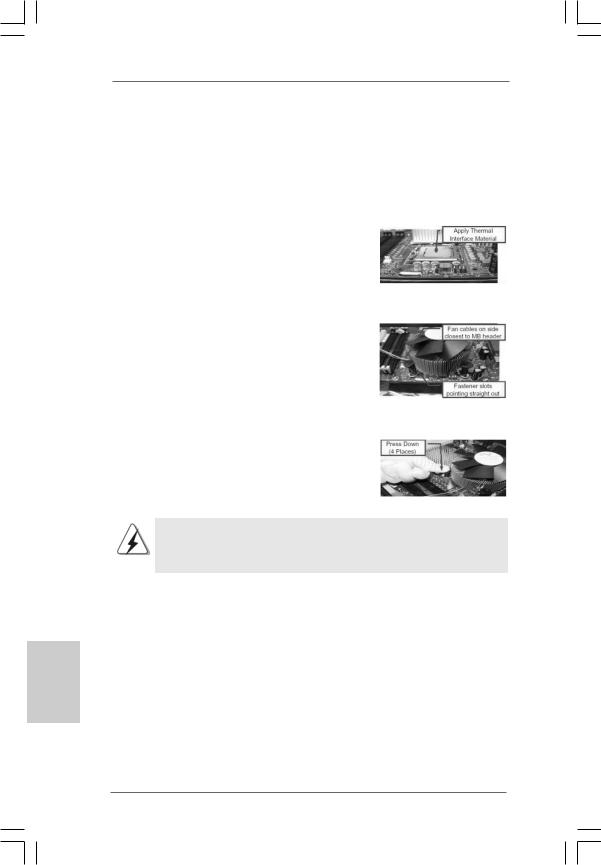
Below is an example to illustrate the installation of the heatsink for 775-LAND CPU. Step 1. Apply thermal interface material onto center
of IHS on the socket surface.
Step 2. |
Place the heatsink onto the socket. Ensure |
|
fan cables are oriented on side closest to the |
|
CPU fan connector on the motherboard |
|
(CPU_FAN1, see page 2, No. 3). |
Step 3. |
Align fasteners with the motherboard |
|
throughholes. |
Step 4. |
Rotate the fastener clockwise, then press |
|
down on fastener caps with thumb to install |
|
and lock. Repeat with remaining fasteners. |
|
|
|
If you press down the fasteners without rotating them clockwise, |
|
the heatsink cannot be secured on the motherboard. |
|
|
Step 5. |
Connect fan header with the CPU fan |
|
connector on the motherboard. |
Step 6. |
Secure excess cable with tie-wrap to ensure |
|
cable does not interfere with fan operation or |
|
contact other components. |
English
1 1
ASRock 2Core1333-2.66G Motherboard
English
2.3 Installation of Memory Modules (DIMM)
2Core1333-2.66G motherboard provides two 240-pin DDRII (Double Data Rate) DIMM slots, and supports Dual Channel Memory Technology. For dual channel configuration, you always need to install two identical (the same brand, speed, size and chiptype) memory modules in the DDRII DIMM slots to activate Dual Channel Memory Technology. Otherwise, it will operate at single channel mode.
1.It is not allowed to install a DDR memory module into DDRII slot; otherwise, this motherboard and DIMM may be damaged.
2.If you install only one memory module or two non-identical memory modules, it is unable to activate the Dual Channel Memory Technology.
Installing a DIMM
Please make sure to disconnect power supply before adding or removing DIMMs or the system components.
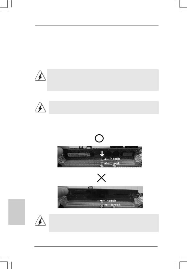
Step 1. Unlock a DIMM slot by pressing the retaining clips outward.
Step 2. Align a DIMM on the slot such that the notch on the DIMM matches the break on the slot.
The DIMM only fits in one correct orientation. It will cause permanent damage to the motherboard and the DIMM if you force the DIMM into the slot at incorrect orientation.
Step 3. Firmly insert the DIMM into the slot until the retaining clips at both ends fully snap back in place and the DIMM is properly seated.
1 2
ASRock 2Core1333-2.66G Motherboard
2.4 Expansion Slots (PCI, HDMR and PCI Express Slots)
There are 2 PCI slots, 1 HDMR slot and 2 PCI Express slots on this motherboard. PCI slots: PCI slots are used to install expansion cards that have the 32-bit PCI
interface.
HDMR slot: HDMR slot is used to insert a HDMR card with v.92 Modem functionality. The HDMR slot is shared with PCI2 slot.
PCIE Slots: PCIE1 (PCIE x16 slot) is used for PCI Express cards with x16 lane width graphics cards.
PCIE2 (PCIE x1 slot) is used for PCI Express cards with x1 lane width cards, such as Gigabit LAN card, SATA2 card, etc.
If you install the add-on PCI Express VGA card to PCIE1 (PCIE x16 slot), the onboard VGA will be disabled. If you install the add-on PCI Express VGA card to PCIE1 (PCIE x16 slot) and adjust the “Internal Graphics Mode Select” BIOS option to [Enabled], the onboard VGA will be enabled, and the primary screen will be onboard VGA.
Installing an expansion card
Step 1. Before installing the expansion card, please make sure that the power supply is switched off or the power cord is unplugged. Please read the documentation of the expansion card and make necessary hardware settings for the card before you start the installation.
Step 2. Remove the bracket facing the slot that you intend to use. Keep the screws for later use.
Step 3. Align the card connector with the slot and press firmly until the card is completely seated on the slot.
Step 4. Fasten the card to the chassis with screws.
English
1 3
ASRock 2Core1333-2.66G Motherboard
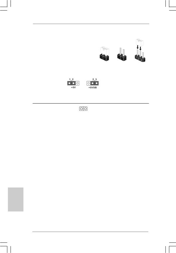
2.5 Jumpers Setup
The illustration shows how jumpers are |
|
|
||
setup. When the jumper cap is placed on |
|
|
||
pins, the jumper is “Short”. If no jumper cap |
|
|
||
is placed on pins, the jumper is “Open”. The |
|
|
||
illustration shows a 3-pin jumper whose pin1 |
Short |
Open |
||
and pin2 are “Short” when jumper cap is |
||||
|
|
|||
placed on these 2 pins. |
|
|
|
|
Jumper |
Setting |
|
Description |
|
PS2_USB_PWR1 |
|
|
Short pin2, pin3 to enable |
|
(see p.2 No. 1) |
|
|
+5VSB (standby) for PS/2 |
|
|
|
|
or USB wake up events. |
|
Note: To select +5VSB, it requires 2 Amp and higher standby current provided by power supply.
Clear CMOS
(CLRCMOS1, 2-pin jumper)
(see p.2 No. 8)
2-pin jumper
Note: CLRCMOS1 allows you to clear the data in CMOS. The data in CMOS includes system setup information such as system password, date, time, and system setup parameters. To clear and reset the system parameters to default setup, please turn off the computer and unplug the power cord from the power supply. After waiting for 15 seconds, use a jumper cap to short 2 pins on CLRCMOS1 for 5 seconds.
English
1 4
ASRock 2Core1333-2.66G Motherboard
2.6 Onboard Headers and Connectors
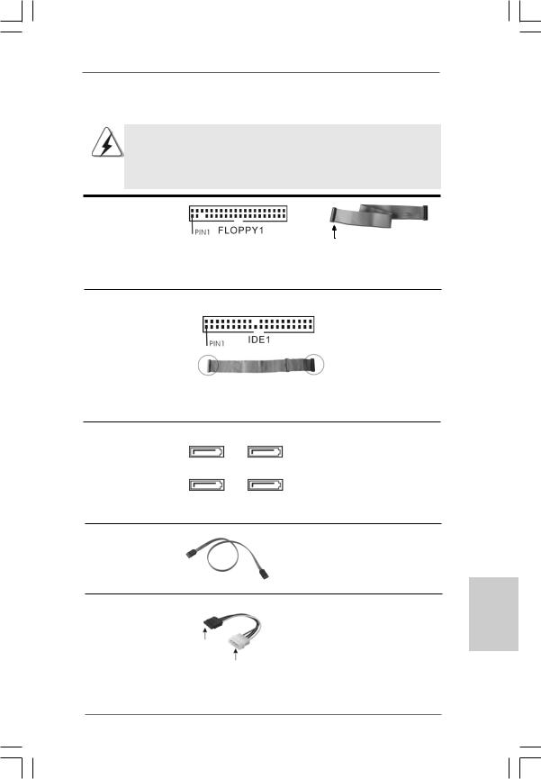
Onboard headers and connectors are NOT jumpers. Do NOT place jumper caps over these headers and connectors. Placing jumper caps over the headers and connectors will cause permanent damage of the motherboard!
FDD connector
(33-pin FLOPPY1)
(see p.2 No. 19)
the red-striped side to Pin1
Note: Make sure the red-striped side of the cable is plugged into Pin1 side of the connector.
Primary IDE connector (Blue)
(39-pin IDE1, see p.2 No. 7)
connect the blue end |
connect the black end |
to the motherboard |
to the IDE devices |
|
80-conductor ATA 66/100 cable |
Note: Please refer to the instruction of your IDE device vendor for the details.
Serial ATAII Connectors
(SATAII_1: see p.2,No. 14) (SATAII_2: see p.2,No. 12) (SATAII_3: see p.2,No. 10) (SATAII_4: see p.2,No. 11)
SATAII_3 SATAII_4
SATAII_1 SATAII_2
These Serial ATAII (SATAII) connectors support SATAII or SATA hard disk for internal storage devices. The current SATAII interface allows up to 3.0 Gb/s data transfer rate.
Serial ATA (SATA) |
Either end of the SATA data cable |
Data Cable |
can be connected to the SATA / |
(Optional) |
SATAII hard disk or the SATAII |
|
connector on the motherboard. |
Serial ATA (SATA) Power Cable
(Optional)
connect to the SATA
HDD power connector
connect to the powersupply
Please connect the black end of SATA power cable to the power connector on each drive. Then connect the white end of SATA power cable to the power connector of the power supply.
1 5
English
ASRock 2Core1333-2.66G Motherboard
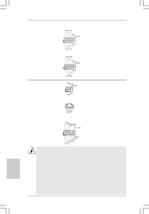
USB 2.0 Headers |
Besides four default USB 2.0 |
(9-pin USB6_7) |
ports on the I/O panel, there are |
(see p.2 No. 17) |
two USB 2.0 headers on this |
|
motherboard. Each USB 2.0 |
|
header can support two USB |
|
2.0 ports. |
(9-pin USB4_5) |
|
(see p.2 No. 18) |
|
Infrared Module Header |
|
This header supports an |
(5-pin IR1) |
|
optional wireless transmitting |
(see p.2 No. 29) |
|
and receiving infrared module. |
|
|
|
Internal Audio Connector |
|
This connector allows you |
(4-pin CD1) |
|
to receive stereo audio input |
(CD1: see p.2 No. 23) |
CD1 |
from sound sources such as |
|
|
a CD-ROM, DVD-ROM, TV |
|
|
tuner card, or MPEG card. |
|
|
|
Front Panel Audio Header |
|
This is an interface for front |
(9-pin HD_AUDIO1) |
|
panel audio cable that allows |
(see p.2 No. 21) |
|
convenient connection and |
|
|
control of audio devices. |
English
1 6
1.High Definition Audio supports Jack Sensing, but the panel wire on the chassis must support HDA to function correctly. Please follow the instruction in our manual and chassis manual to install your system.
2.If you use AC’97 audio panel, please install it to the front panel audio header as below:
A.Connect Mic_IN (MIC) to MIC2_L.
B.Connect Audio_R (RIN) to OUT2_R and Audio_L (LIN) to OUT2_L.
C.Connect Ground (GND) to Ground (GND).
D.MIC_RET and OUT_RET are for HD audio panel only. You don’t need to connect them for AC’97 audio panel.
E.Enter BIOS Setup Utility. Enter Advanced Settings, and then select Chipset Configuration. Set the Front Panel Control option from [Auto] to [Enabled].
ASRock 2Core1333-2.66G Motherboard
F.Enter Windows system. Click the icon on the lower right hand taskbar to enter Realtek HD Audio Manager. Click “Audio I/O”,
select “Connector Settings” |
, choose “Disable front |
panel jack detection”, and save the change by clicking “OK”.
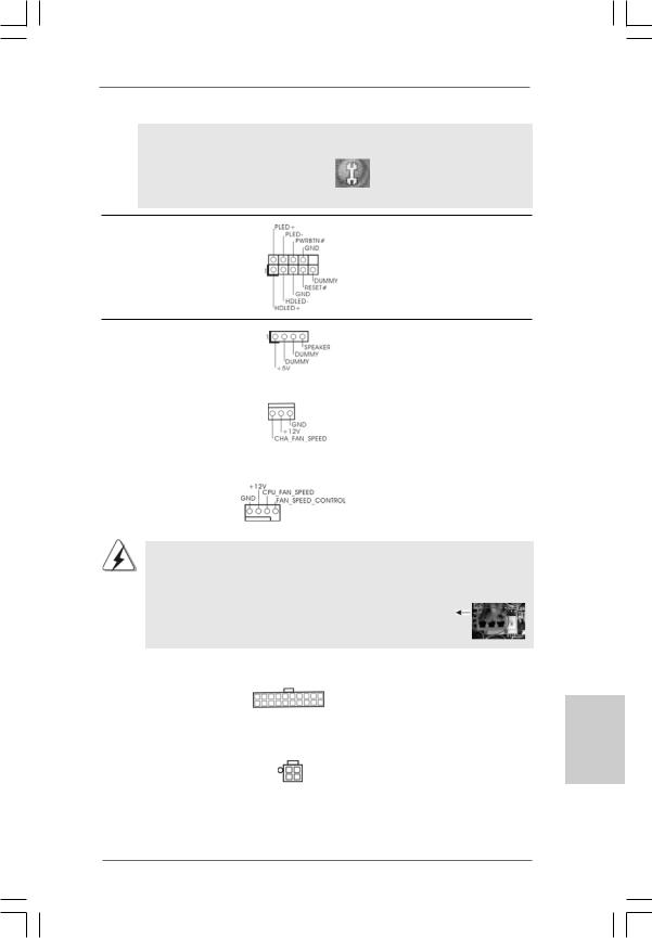
System Panel Header |
This header accommodates |
(9-pin PANEL1) |
several system front panel |
(see p.2 No. 13) |
functions. |
Chassis Speaker Header |
|
|
Please connect the chassis |
(4-pin SPEAKER 1) |
|
|
speaker to this header. |
(see p.2 No. 15) |
|
|
|
|
|
|
|
Chassis Fan Connector |
|
|
Please connect a chassis fan |
(3-pin CHA_FAN1) |
|
|
cable to this connector and |
(see p.2 No. 16) |
|
|
match the black wire to the |
|
|
|
ground pin. |
|
|
|
|
CPU Fan Connector |
|
|
Please connect a CPU fan cable |
(4-pin CPU_FAN1) |
|
|
to this connector and match |
(see p.2 No. 3) |
|
|
the black wire to the ground pin. |
1 |
2 |
3 |
4 |
Though this motherboard provides 4-Pin CPU fan (Quiet Fan) support, the 3-Pin CPU fan still can work successfully even without the fan speed control function. If you plan to connect the 3-Pin CPU fan to the CPU fan connector on this motherboard, please connect it to Pin 1-3.
|
Pin 1-3 Connected |
|
3-Pin Fan Installation |
|
|
ATX Power Connector |
Please connect an ATX power |
(20-pin ATXPWR1) |
supply to this connector. |
(see p.2 No. 26) |
|
|
|
ATX 12V Connector |
Please note that it is necessary |
(4-pin ATX12V1) |
to connect a power supply with |
(see p.2 No. 2) |
ATX 12V plug to this connector |
|
so that it can provides sufficient |
|
power. Failing to do so will cause |
|
the failure to power up. |
1 7
English
ASRock 2Core1333-2.66G Motherboard
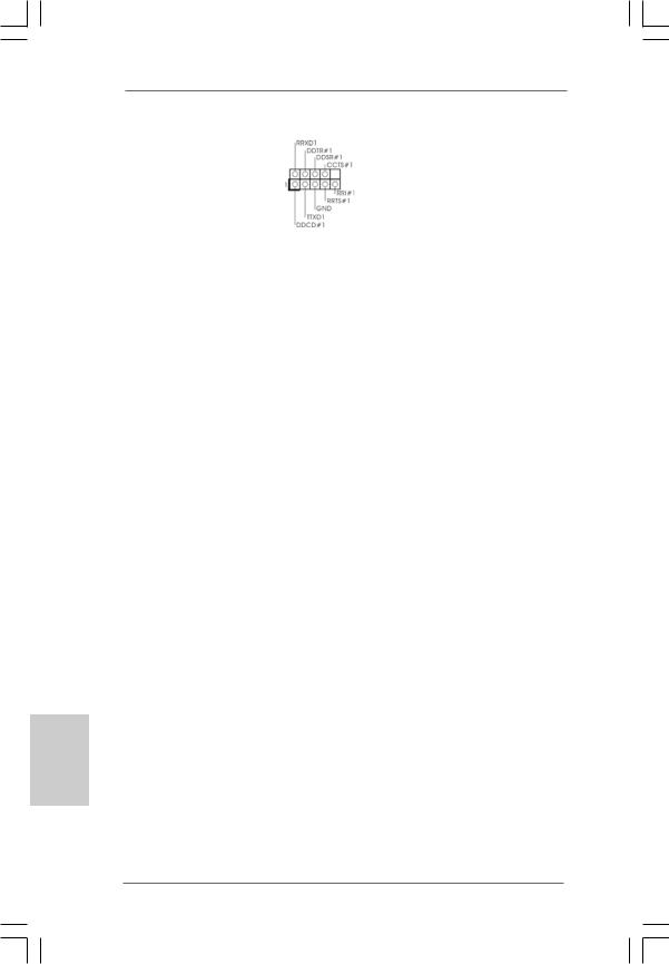
Serial port Header |
This COM1 header supports |
(9-pin COM1) |
a serial port module. |
(see p.2 No. 28) |
|
English
1 8
ASRock 2Core1333-2.66G Motherboard
2.7SATAII Hard Disk Setup Guide
Before installing SATAII hard disk to your computer, please carefully read below SATAII hard disk setup guide. Some default setting of SATAII hard disks may not be at SATAII mode, which operate with the best performance. In order to enable SATAII function, please follow the below instruction with different vendors to correctly adjust your SATAII hard disk to SATAII mode in advance; otherwise, your SATAII hard disk may fail to run at SATAII mode.
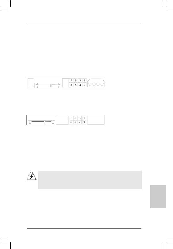
Western Digital
If pin 5 and pin 6 are shorted, SATA 1.5Gb/s will be enabled.
On the other hand, if you want to enable SATAII 3.0Gb/s, please remove the jumpers from pin 5 and pin 6.
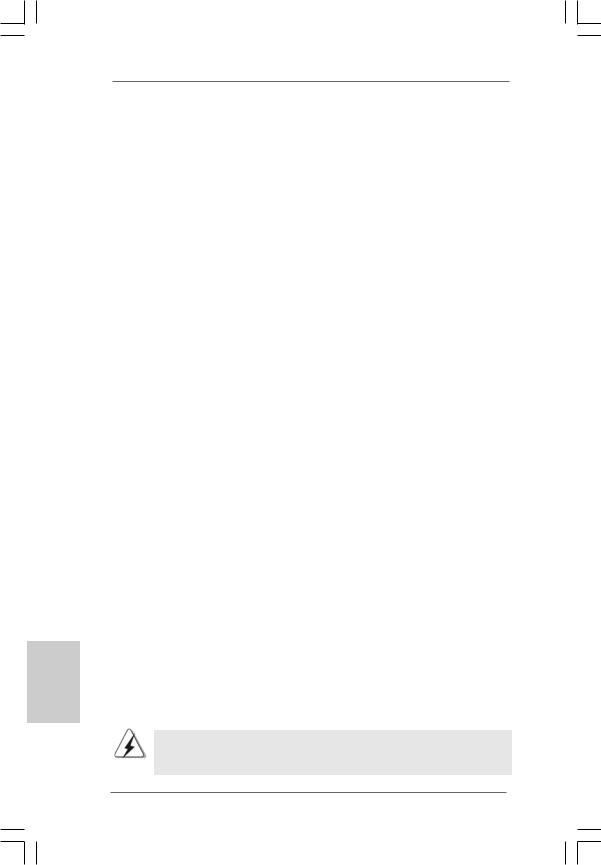
SAMSUNG
If pin 3 and pin 4 are shorted, SATA 1.5Gb/s will be enabled.
On the other hand, if you want to enable SATAII 3.0Gb/s, please remove the jumpers from pin 3 and pin 4.
HITACHI
Please use the Feature Tool, a DOS-bootable tool, for changing various ATA features. Please visit HITACHI’s website for details: http://www.hitachigst.com/hdd/support/download.htm
The above examples are just for your reference. For different SATAII hard disk products of different vendors, the jumper pin setting methods may not be the same. Please visit the vendors’ website for the updates.
English
1 9
ASRock 2Core1333-2.66G Motherboard
English
2.8Serial ATA (SATA) / Serial ATAII (SATAII) Hard Disks
Installation
This motherboard adopts Intel® ICH7 south bridge chipset that supports Serial ATA (SATA) / Serial ATAII (SATAII) hard disks. You may install SATA / SATAII hard disks on this motherboard for internal storage devices. This section will guide you to install the SATA / SATAII hard disks.
STEP 1: Install the SATA / SATAII hard disks into the drive bays of your chassis. STEP 2: Connect the SATA power cable to the SATA / SATAII hard disk.
STEP 3: Connect one end of the SATA data cable to the motherboard’s SATAII connector.
STEP 4: Connect the other end of the SATA data cable to the SATA / SATAII hard disk.
2.9Driver Installation Guide
To install the drivers to your system, please insert the support CD to your optical drive first. Then, the drivers compatible to your system can be auto-detected and listed on the support CD driver page. Please follow the order from up to bottom side to install those required drivers. Therefore, the drivers you install can work properly.
2.10 HDMR Card and Driver Installation
If you do not insert HDMR card to this motherboard, and you finish installing all drivers to your system now, but in the future, you plan to use HDMR card function on this motherboard, please follow the steps below then.
1.Insert HDMR card to HDMR slot on this motherboard. Please make sure that the HDMR card is completely seated on the slot.
2.Install HDMR card driver from our support CD to your system.
3.Reboot your system.
2.11 Untied Overclocking Technology
This motherboard supports Untied Overclocking Technology, which means during overclocking, FSB enjoys better margin due to fixed PCI / PCIE buses. Before you enable Untied Overclocking function, please enter “Overclock Mode” option of BIOS setup to set the selection from [Auto] to [CPU, PCIE, Async.]. Therefore, CPU FSB is untied during overclocking, but PCI / PCIE buses are in the fixed mode so that FSB can operate under a more stable overclocking environment.
Please refer to the warning on page 6 for the possible overclocking risk before you apply Untied Overclocking Technology.
2 0
ASRock 2Core1333-2.66G Motherboard
3. BIOS Information
The Flash Memory on the motherboard stores BIOS Setup Utility. When you start up the computer, please press <F2> during the Power-On-Self-Test (POST) to enter BIOS Setup utility; otherwise, POST continues with its test routines. If you wish to enter BIOS Setup after POST, please restart the system by pressing <Ctl> + <Alt> + <Delete>, or pressing the reset button on the system chassis. The BIOS Setup program is designed to be user-friendly. It is a menu-driven program, which allows you to scroll through its various sub-menus and to select among the predetermined choices. For the detailed information about BIOS Setup, please refer to the User Manual (PDF file) contained in the Support CD.
4. Software Support CD information
This motherboard supports various Microsoft® Windows® operating systems: 2000 / XP / XP 64-bit / VistaTM / VistaTM 64-bit. The Support CD that came with the motherboard contains necessary drivers and useful utilities that will enhance motherboard features. To begin using the Support CD, insert the CD into your CD-ROM drive. It will display the Main Menu automatically if “AUTORUN” is enabled in your computer. If the Main Menu does not appear automatically, locate and double-click on the file “ASSETUP. EXE” from the BIN folder in the Support CD to display the menus.
English
2 1
ASRock 2Core1333-2.66G Motherboard
1. Einführung
Wir danken Ihnen für den Kauf des ASRock 2Core1333-2.66G Motherboard, ein zuverlässiges Produkt, welches unter den ständigen, strengen Qualitätskontrollen von ASRock gefertigt wurde. Es bietet Ihnen exzellente Leistung und robustes Design, gemäß der Verpflichtung von ASRock zu Qualität und Halbarkeit.
Diese Schnellinstallationsanleitung führt in das Motherboard und die schrittweise Installation ein. Details über das Motherboard finden Sie in der Bedienungsanleitung auf der Support-CD.
Da sich Motherboard-Spezifikationen und BIOS-Software verändern können, kann der Inhalt dieses Handbuches ebenfalls jederzeit geändert werden. Für den Fall, dass sich Änderungen an diesem Handbuch ergeben, wird eine neue Version auf der ASRock-Website, ohne weitere Ankündigung, verfügbar sein. Die neuesten Grafikkarten und unterstützten CPUs sind auch auf der ASRock-Website aufgelistet.
ASRock-Website: http://www.asrock.com
1.1 Kartoninhalt
ASRock 2Core1333-2.66G-Motherboard zusammen mit ausgewählter
Dualkern-CPU, die mit FSB1333 / 2,66 GHz getaktet ist
(Micro ATX-Formfaktor: 24.4 cm x 22.9 cm; 9.6 Zoll x 9.0 Zoll) ASRock 2Core1333-2.66G Schnellinstallationsanleitung
ASRock 2Core1333-2.66G_ Support-CD
Ein 80-adriges Ultra-ATA 66/100 IDE-Flachbandkabel Ein Flachbandkabel für ein 3,5-Zoll-Diskettenlaufwerk Ein Seriell-ATA- (SATA) Datenkabel (Option)
Ein Seriell-ATA (SATA) Festplattennetzkabel (Option) Ein HD 8CH I/O Shield
Ein COM Port-Anschlusshalter
Deutsch
2 2
ASRock 2Core1333-2.66G Motherboard
1.2Spezifikationen
Plattform |
- Micro ATX-Formfaktor: 24.4 cm x 22.9 cm; 9.6 Zoll x 9.0 Zoll |
|
CPU |
- Paket mit ausgewählter Dualkern-CPU mit FSB1333 / |
|
|
2,66 GHz |
|
|
* Dieses Motherboard unterstützt auch die nachstehenden CPU- |
|
|
Spezifikationen: |
|
|
- LGA 775 für Intel® Dual Core CoreTM 2 Extreme- / CoreTM 2 Duo- / |
|
|
Pentium® D- / Pentium® Dual Core- / Pentium® 4- / Celeron®- / |
|
|
Celeron® D- Prozessoren |
|
|
- Kompatibilität mit allen Zentraleinheiten (CPU) FSB1333/1066/ |
|
|
800/533MHz außer Quadrangel Kerne (siehe VORSICHT 1) |
|
|
- Unterstützt Hyper-Threading-Technologie |
|
|
- Unterstützt Untied-Übertaktungstechnologie (siehe VORSICHT 2) |
|
|
- Unterstützt EM64T-CPU |
|
Chipsatz |
- Northbridge: Intel® 945GC A2 |
|
|
- Southbridge: Intel® ICH7 |
|
Speicher |
- Unterstützung von Dual-Kanal-DDRII-Speichertechnologie |
|
|
(siehe VORSICHT 3) |
|
|
- 2 x Steckplätze für DDRII |
|
|
- Unterstützt DDRII667/533 (siehe VORSICHT 4) |
|
|
- Max. 4GB (siehe VORSICHT 5) |
|
Hybrid Booster |
- Schrittloser CPU-Frequenz-Kontrolle (siehe VORSICHT 6) |
|
|
- ASRock U-COP (siehe VORSICHT 7) |
|
|
- Boot Failure Guard (B.F.G. – Systemstartfehlerschutz) |
|
Erweiterungs- |
- 1 x PCI Express x16-Steckplätze |
|
steckplätze |
- 1 x PCI Express x1-Steckplätze |
|
|
- 2 x PCI -Steckplätze |
|
|
- 1 x HDMR-Steckplätze |
|
Onboard-VGA |
- Intel® Graphics Media Accelerator 950 |
|
|
- Pixel Shader 2.0, DX9.0 VGA |
|
|
- Maximal gemeinsam genutzter Speicher 224MB |
|
|
(siehe VORSICHT 8) |
|
Audio |
- 7.1 CH Windows® VistaTM Premium Level HD Audio |
|
|
(ALC888 Audio Codec) |
|
LAN |
- Realtek PCIE x1 LAN 8101E |
|
|
- Speed: 10/100 Ethernet |
|
|
- Unterstützt Wake-On-LAN |
|
E/A-Anschlüsse |
HD 8CH I/O |
|
an der |
- 1 x PS/2-Mausanschluss |
|
Rückseite |
- 1 x PS/2-Tastaturanschluss |
|
2 3
Deutsch
ASRock 2Core1333-2.66G Motherboard

Deutsch
|
- 1 x VGA port |
|
- 1 x Paralleler port: Unterstützung für ECP / EPP |
|
- 4 x Standard-USB 2.0-Anschlüsse |
|
- 1 x RJ-45 port |
|
- HD Audiobuchse: Lautsprecher seitlich / Lautsprecher hinten |
|
/ Mitte/Bass / Audioeingang/ Lautsprecher vorne / Mikrofon |
|
(siehe VORSICHT 9) |
Anschlüsse |
- 4 x SATAII-Anschlüsse, unterstützt bis 3.0 Gb/s |
|
Datenübertragungsrate (Unterstützt keine “RAID”- und “Hot- |
|
Plug”-Funktionen) (siehe VORSICHT 10) |
|
- 1 x ATA100 IDE-Anschlüsse (Unterstützt bis 2 IDE-Geräte) |
|
- 1 x FDD-Anschlüsse |
|
- 1 x Infrarot-Modul-Header |
|
- 1 x COM-Anschluss-Header |
|
- CPU/Gehäuse-Lüfteranschluss |
|
- 20-pin ATX-Netz-Header |
|
- 4-pin anschluss für 12V-ATX-Netzteil |
|
- Interne Audio-Anschlüsse |
|
- Anschluss für Audio auf der Gehäusevorderseite |
|
- 2 x USB 2.0-Anschlüsse (Unterstützung 4 |
|
zusätzlicher USB 2.0-Anschlüsse) (siehe VORSICHT 11) |
BIOS |
- 4Mb AMI BIOS |
|
- AMI legal BIOS mit Unterstützung für “Plug and Play” |
|
- ACPI 1.1-Weckfunktionen |
|
- JumperFree-Modus |
|
- SMBIOS 2.3.1 |
Support-CD |
- Treiber, Dienstprogramme, Antivirussoftware |
|
(Probeversion) |
Hardware Monitor |
- Überwachung der CPU-Temperatur |
|
- Motherboardtemperaturerkennung |
|
- Drehzahlmessung für CPU-Lüfter |
|
- Drehzahlmessung für Gehäuselüfter |
|
- CPU-Lüftergeräuschdämpfung |
|
- Spannungsüberwachung: +12V, +5V, +3.3V, Vcore |
Betriebssysteme |
- Unterstützt Microsoft® Windows® 2000 / XP / XP 64-Bit / |
|
VistaTM / VistaTM 64-Bit (siehe VORSICHT 12) |
Zertifizierungen |
- FCC, CE, WHQL |
2 4
ASRock 2Core1333-2.66G Motherboard

WARNUNG
Beachten Sie bitte, dass Overclocking, einschließlich der Einstellung im BIOS, Anwenden der Untied Overclocking-Technologie oder Verwenden von Overclocking-Werkzeugen von Dritten, mit einem gewissen Risiko behaftet ist. Overclocking kann sich nachteilig auf die Stabilität Ihres Systems auswirken oder sogar Komponenten und Geräte Ihres Systems beschädigen. Es geschieht dann auf eigene Gefahr und auf Ihre Kosten. Wir übernehmen keine Verantwortung für mögliche Schäden, die aufgrund von Overclocking verursacht wurden.
VORSICHT!
1. FSB1333-CPU wird nach Uhrzeitmode operatieren. In diese Situation wird PCIE Frequenz auch nach Uhrzeitmode zu 115MHz.
2. Dieses Motherboard unterstützt die Untied-Übertaktungstechnologie. Unter “Entkoppelte Übertaktungstechnologie” auf Seite 40 finden Sie detaillierte Informationen.
3. Dieses Motherboard unterstützt Dual-Kanal-Speichertechnologie. Vor Implementierung der Dual-Kanal-Speichertechnologie müssen Sie die Installationsanleitung für die Speichermodule auf Seite 31 zwecks richtiger Installation gelesen haben.
4. Die unterstützten Arbeitsspeicherfrequenzen und die entsprechende CPU FSB-Frequenz entnehmen Sie bitte der nachstehenden Tabelle.
CPU FSB-Frequenz |
Unterstützte Arbeitsspeicherfrequenz |
1333 |
DDRII533*, DDRII667 |
1066 |
DDRII533, DDRII667 |
800 |
DDRII400, DDRII533, DDRII667 |
533 |
DDRII400, DDRII533 |
* Bei Verwendung einer FSB1333-CPU auf diesem Motherboard läuft es mit DDRII500, wenn Sie ein DDRII533-Speichermodul verwenden.
5. Aufgrund von Chipset-Einschränkungen könnte unter Windows® 2000, Windows® XP, Windows® XP 64-Bit, Windows® VistaTM und Windows® VistaTM 64-Bit die für das System reservierte Speichergröße unterhalb von 4 GB liegen.
6. Obwohl dieses Motherboard stufenlose Steuerung bietet, wird Overclocking nicht empfohlen. Frequenzen, die über den für den jeweiligen Prozessor vorgesehenen liegen, können das System instabil werden lassen oder die CPU beschädigen.
7. Wird eine Überhitzung der CPU registriert, führt das System einen automatischen Shutdown durch. Bevor Sie das System neu starten, prüfen Sie bitte, ob der CPU-Lüfter am Motherboard richtig funktioniert, und stecken Sie bitte den Stromkabelstecker aus und dann wieder ein. Um die Wärmeableitung zu verbessern, bitte nicht vergessen, etwas Wärmeleitpaste zwischen CPU und Kühlkörper zu sprühen.
8. Die Maximalspeichergröße ist von den Chipshändler definiert und umgetauscht. Bitte überprüfen Sie Intel® website für die neuliche Information.
2 5
Deutsch
ASRock 2Core1333-2.66G Motherboard
9.Der Mikrofoneingang dieses Motherboards unterstützt Stereound MonoModi. Der Audioausgang dieses Motherboards unterstützt 2-Kanal-, 4-Kanal-, 6-Kanal- und 8-Kanal-Modi. Stellen Sie die richtige Verbindung anhand der Tabelle auf Seite 3 her.
10.Bevor Sie eine SATA II Festplatte mit dem SATA II Anschluss verbinden, lesen Sie bitte die “Anleitung zur SATA II Festplatteneinrichtung“ auf Seite 38, um Ihre SATA II Festplatte in den SATA II Modus umzuschalten. SATA-Festplatten können Sie auch direkt mit dem SATA II-Anschluss verbinden.
11.Das Power Management für USB 2.0 arbeitet unter Microsoft® Windows® VistaTM 64-Bit / VistaTM / XP 64-Bit / XP SP1 oder SP2/2000 SP4 einwandfrei.
12.Der Microsoft® Windows® VistaTM / VistaTM 64-Bit Treiber wird ständig aktualisiert. Sobald wir den neuesten Treiber haben, stellen wir ihn auf unserer Website zur Verfügung. Bitte besuchen Sie unsere Website für den Microsoft® Windows® VistaTM / VistaTM 64-Bit Treiber und verwandte Informationen.
ASRock-Website http://www.asrock.com
1.3Minimale Hardwarevorausetzungen für Windows®
VistaTM Premium 2007 und Basic Logo
Systemintegratoren und Anwender unseres Motherboards, die ihre Rechner auf die Vergabe des Windows® VistaTM Premium 2007 und BasicLogos vorbereiten möchten, finden die minimalen hardwarevoraussetzungen in der folgenden Tabelle.
Deutsch
2 6
Speicher |
512 MB x 2 Dual Channel (Premium) |
|
512 MB Single Channel (Basic) |
|
256 MB x 2 Dual Channel (Basic) |
VGA |
DX9.0 mit WDDM-Treiber |
|
|
*Wenn Sie einen Onboard-VGA-Chip für das Anzeigen desWindows® VistaTM-Log verwenden möchten, behalten Sie bitte die Standardeinstellung der Funktion “DVMTModusauswahl” im BIOS.
*Sofern Sie eine externe Grafikkarte mit diesem Motherboard verwenden möchten, lesen Sie bitte unter Premium Discrete-Anforderungen auf unseren Internetseiten nach: http://www.asrock.com
*Nach dem ersten Juni, 2007 sind , all Windows® VistaTM Systems dafür erforderlich, mit der Minimalforderung der obengenannte Hardware übereinzustimmen, um Windows® VistaTM Premium 2007 logo.zu befähigen.
ASRock 2Core1333-2.66G Motherboard
2. Installation
Sicherheitshinweise vor der Montage
Bitte nehmen Sie die folgende Sicherheitshinweise zur Kenntnis, bevor Sie das Motherboard einbauen oder Veränderungen an den Einstellungen vornehmen.
1.Trennen Sie das System vom Stromnetz, bevor Sie eine ystemkomponente berühren, da es sonst zu schweren Schäden am Motherboard oder den sonstigen internen, bzw. externen omponenten kommen kann.
2.Um Schäden aufgrund von statischer Elektrizität zu vermeiden, das Motherboard NIEMALS auf einen Teppich o.ä.legen. Denken Sie außerem daran, immer ein geerdetes Armband zu tragen oder ein geerdetes Objekt aus Metall zu berühren, bevor Sie mit Systemkomponenten hantieren.
3.Halten Sie Komponenten immer an den Rändern und vermeiden Sie Berührungen mit den ICs.
4.Wenn Sie Komponenten ausbauen, legen Sie sie immer auf eine antistatische Unterlage, oder zurück in die Tüte, mit der die Komponente geliefert wurde.
5.Wenn Sie das Motherboard mit den Schrauben an dem Computergehäuse befestigen, überziehen Sie bitte die Schrauben nicht! Das Motherboard kann sonst beschädigt werden.
2.1CPU Installation
Dieses Motherboard wird mit einer ausgesuchten Dual Core-CPU, FSB 1333 / 2,66 GHz geliefert. Bitte entfernen Sie nicht die ASRock-CPU-Aufkleber an beiden Seiten des CPU-Sockels auf dem Motherboard. Falls die Aufkleber
beschädigt oder entfernt wurden oder das Wort „ ASRock-CPU-Aufkleber
VOID“ tragen, übernimmt ASRock keinen Kundendienst für diese CPU.
Zukünftig können Sie auch andere kompatible |
(Ladeplatte) |
(Sockel) |
Intel 775-LAND-CPUs mit diesem Motherboard |
|
|
verwenden. Zur Installation der Intel 775-LAND |
(Kontaktreihe) |
|
-CPU führen Sie bitte die nachstehenden Schritte |
|
|
aus. ASRock erinnert Sie daran, dass die Firma |
|
|
bei Verwendung einer anderen CPU Ihrerseits auf |
|
|
diesem Motherboard keinen Kundendienst für die |
|
|
mitgelieferte CPU übernimmt. |
775-Pin Sockel Übersicht |
|
Bevor Sie die 775-Pin CPU in den Sockel sitzen, prüfen Sie bitte, ob die CPU-Oberfläche sauber ist und keine der Kontakte verbogen sind. Setzen Sie die CPU nicht mit Gewalt in den Sockel, dies kann die CPU schwer beschädigen.
2 7
Deutsch
ASRock 2Core1333-2.66G Motherboard
Schritt 1. Öffnen Sie den Sockel:
Schritt 1-1. Öffnen Sie den Hebel, indem Sie ihn nach unten drücken und aushaken.
Deutsch
Schritt 1-2. Drehen Sie den Ladehebel, bis er in geöffneter Position steht, ca. 135 Grad.
Schritt 1-3. Drehen Sie die Ladeplatte, bis sie in geöffneter Position steht, ca. 100 Grad.
Schritt 2. 775-Pin CPU einstecken:
Schritt 2-1. Halten Sie die CPU an den mit schwarzen Linien gekennzeichneten Seiten.
LinieSchwarze |
LinieSchwarze |
Schritt 2-2. Halten Sie das Teil mit dem IHS (Integrated Heat Sink – integrierter Kühlkörper) nach oben. Suchen Sie Pin 1 und die zwei Orientierungseinkerbungen.
|
Pin1 |
|
Pin1 |
Ausrichtungsmarkierung |
Ausrichtungsmarkierung |
Orientierungskerbe |
Orientierungskerbe |
|
|
|
775-PinSockel |
775-Pin CPU
Um die CPU ordnungsgemäß einsetzen zu können, richten Sie die zwei Orientierungskerben der CPU mit den beiden Markierungen des Sockels aus.
Schritt 2-3. Drücken Sie die CPU vorsichtig in vertikaler Richtung in den Sockel.
2 8
ASRock 2Core1333-2.66G Motherboard
Schritt 2-4. Prüfen Sie, dass die CPU ordnungsgemäß im Sockel sitzt und die Orientierungskerben einwandfrei in den entsprechenden Auskerbungen sitzen.
Schritt 3. PnP-Kappe entfernen (Pick and Place-Kappe): Halten Sie den Rand der Ladeplatte mit Zeigefinger und Daumen Ihrer linken Hand, halten Sie die PnP-Kappe mit dem Daumen der rechten Hand und ziehen Sie die Kappe vom Sockel während Sie auf die Mitte der Kappe drücken, um ein Entfernen zu erleichtern.
1.Verwenden Sie beim Entfernen die Kappenlasche und vermeiden Sie ein Abreißen der PnP-Kappe.
2.Diese Kappe muss angebracht werden, falls Sie das Motherboard zur Reparatur bringen.
Schritt 4. Sockel schließen:
Schritt 4-1. Drehen Sie die Ladeplatte auf den Kühlkörper (IHS).
Schritt 4-2. Drücken Sie leicht auf die Ladeplatte und schließen Sie den Ladehebel.
Schritt 4-3. Sichern Sie Ladehebel und Ladeplatte mithilfe des Hebelverschlusses.
Deutsch
2 9
ASRock 2Core1333-2.66G Motherboard
Deutsch
2.2 Installation des CPU-Lüfters und Kühlkörpers
Für Installationshinweise, siehe Betriebsanleitung Ihres CPU-Lüfters und Kühlkörpers.
Unten stehend ein Beispiel zur Installation eines Kühlkörpers für den 775-Pin CPU.
Schritt 1. Geben Sie Wärmeleitmaterial auf die Mitte des IHS, auf die Sockeloberfläche.
Schritt 2. Setzen Sie den Kühlkörper auf den Sockel. Prüfen Sie, dass die Lüfterkabel auf der Seite am nächsten zum CPU-Lüfter- Anschluss des Motherboards verlaufen (CPU_FAN1, siehe Seite 2, Nr. 3).
Schritt 3. Richten Sie Verbindungselemente und Löcher im Motherboard aus.
Schritt 4. Drehen Sie die Verbindungselemente im Uhrzeigersinn und drücken Sie mit dem Daumen auf die Kappen der Elemente zum Feststellen. Wiederholen Sie dies mit den anderen Verbindungselementen.
(Tragen Sie Wärmeleitmaterial auf. )
(Lüfterkabel auf der Seite am nächsten zum Anschluss des Motherboards)
(Schlitze der Verbindungselemente nachaußen)
(Nach unten drücken (4 Stellen))
Wenn Sie die Verbindungselemente nur drücken, ohne sie im Uhrzeigersinn zu drehen, wird der Kühlkörper nicht ordnungsgemäß am Motherboard befestigt.
Schritt 5. Schließen Sie den Lüfter an den CPU-
Lüfteranschluss des Motherboards.
Schritt 6. Befestigen Sie überschüssiges Kabel mit
Band, um eine Störung des Lüfters oder
Kontakt mit anderen Teilen zu vermeiden.
3 0
ASRock 2Core1333-2.66G Motherboard
 Loading...