


use and maintenance
Gulliver 50

© 1996 aprilia s.p.a. - Noale (VE)
This manual is to be considered an integral part of the vehicle, which must be delivered complete with it also in case of resale.
aprilia s.p.a. reserves the right to modify its models at any time, without prejudice to the main characteristics here described.
All rights as to electronic storage, reproduction and total or partial adaptation, with any means, are reserved for all Countries.
The mention to products or services supplied by third parties is made only for information purposes and it is not binding in any case.
aprilia s.p.a. takes no responsibility as to the performance or the use of said products.
First edition: september 1996
Reprint: february 1997, mars 1999
Produced and printed by:
editing division
Soave (VERONA) - Italy
Tel. +39 - 045 76 11 911
Fax +39 - 045 76 12 241
E-mail: customer@stp.it
www.stp.it
On behalf of: aprilia s.p.a.
via G. Galilei, 1 - 30033 Noale (VE) - Italy Tel. +39 - 041 58 29 111
Fax +39 - 041 44 10 54 www.aprilia.com
2 use and maintenance Gulliver 50
&/2%7/2$
Before starting the engine, carefully read this manual, paying particular attention to the chapter "RIDING SAFELY".
Your and other people’s safety depends not only on your quickness of reflexes and on your agility, but also on what you know about the vehicle, on its efficiency and on your knowledge of the basic information for RIDING SAFELY.
Therefore, get a thorough knowledge of the vehicle, in such a way as to be able to drive in the traffic safely.
For the controls and repairs not expressly described in this manual, for the purchase of aprilia Genuine Spare Parts, accessories and other products, as well as for specific technical advice, contact only aprilia Authorized Outlets and Official Dealers, who can ensure you reliable and prompt servicing.
Thank you for choosing aprilia. We wish you a nice ride.
IMPORTANT:
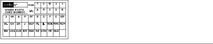
When asking your Dealer for spare parts, specify the spare parts code indicated on the SPARE PARTS IDENTIFICATION LABEL.
Write down the identification code in the space here below, in order to remember it also in case of loss or deterioration of the label. The label is placed under the inspection cover, sticked to the frame.
Carefully observe the instructions preceded by the following warning signs:
aSafety norms and regulations to protect the driver and other people from severe injuries or grave risks.
cIndicationsinformation.to make the operations easier. Technical
In this manual the various versions are indicated by the following symbols:
1liquid-cooled version
2catalytic version
VERSION: |
|
I Italy |
V Poland |
U United Kingdom |
% Israel |
A Austria |
K South Korea |
P Portugal |
M Malaysia |
" Finland |
R Chile |
B Belgium |
Q Bermuda |
D Germany |
- ofUnitedAmericaStates |
F France |
^ Australia |
E Spain |
Í Brazil |
G Greece |
° South Africa |
O Holland |
Î New Zealand |
C Switzerland |
[ Canada |
ˆ Denmark |
` Croatia |
J Japan |
Ñ Slovenia |
S Singapore |
|
use and maintenance Gulliver 50 3

'%.%2!, #/.4%.43 |
|
RIDING SAFELY............................................................................................... |
5 |
BASIC SAFETY RULES ............................................................................. |
6 |
CLOTHING ................................................................................................. |
9 |
ACCESSORIES........................................................................................ |
10 |
LOAD ........................................................................................................ |
10 |
ARRANGEMENT OF THE MAIN ELEMENTS ............................................... |
12 |
ARRANGEMENT OF THE INSTRUMENTS ................................................... |
14 |
INSTRUMENTS AND INDICATORS .............................................................. |
14 |
INSTRUMENT AND INDICATOR TABLE ................................................ |
15 |
MAIN INDEPENDENT CONTROLS ............................................................... |
16 |
CONTROLS ON THE LEFT SIDE OF THE HANDLEBARS .................... |
16 |
CONTROLS ON THE RIGHT SIDE OF THE HANDLEBARS .................. |
17 |
IGNITION SWITCH................................................................................... |
18 |
STEERING LOCK..................................................................................... |
18 |
AUXILIARY EQUIPMENT............................................................................... |
19 |
SETTING THE CLOCK............................................................................. |
19 |
CHANGING THE CLOCK CELL............................................................... |
19 |
UNLOCKING/LOCKING THE SADDLE.................................................... |
20 |
SADDLE LOCKING ADJUSTMENT ......................................................... |
20 |
CRASH HELMET / GLOVE COMPARTMENT ......................................... |
21 |
TRANSPORTING CUMBERSOME OBJECTS ........................................ |
21 |
GLOVE / TOOL KIT COMPARTMENT..................................................... |
22 |
BAG HOOK............................................................................................... |
22 |
ANTI-THEFT HOOK ................................................................................. |
22 |
MAIN COMPONENTS..................................................................................... |
23 |
FUEL......................................................................................................... |
23 |
MIXER OIL TANK ..................................................................................... |
24 |
BRAKE FLUID |
|
(RECOMMENDATIONS) .......................................................................... |
24 |
FRONT BRAKE ........................................................................................ |
25 |
REAR BRAKE........................................................................................... |
26 |
TYRES...................................................................................................... |
27 |
COOLANT 1......................................................................................... |
28 |
CATALYTIC SILENCER 2................................................................... |
30 |
INSTRUCTIONS FOR USE............................................................................. |
31 |
PRELIMINARY CHECKING OPERATIONS............................................. |
31 |
STARTING................................................................................................ |
32 |
DEPARTURE AND DRIVE ....................................................................... |
34 |
RUNNING-IN ............................................................................................ |
35 |
STOPPING AND PARKING ..................................................................... |
35 |
POSITIONING THE VEHICLE ON THE STAND...................................... |
35 |
SUGGESTIONS TO PREVENT THEFT................................................... |
36 |
MAINTENANCE .............................................................................................. |
37 |
REGULAR SERVICE INTERVALS CHART ............................................. |
37 |
IDENTIFICATION DATA........................................................................... |
38 |
AIR CLEANER ......................................................................................... |
39 |
CHECKING THE TRANSMISSION OIL LEVEL....................................... |
40 |
CHANGING THE TRANSMISSION OIL .................................................. |
41 |
FRONT WHEEL....................................................................................... |
42 |
REAR WHEEL ......................................................................................... |
44 |
GREASING THE REAR BRAKE CAM PIN.............................................. |
45 |
CHECKING THE PAD WEAR.................................................................. |
46 |
CHECKING THE SHOE WEAR ............................................................... |
46 |
CHECKING THE STEERING................................................................... |
47 |
CHECKING THE ENGINE FULCRUM AXIS ........................................... |
47 |
REMOVING THE INSPECTION COVER................................................. |
48 |
REMOVING THE LOWER COVERS OF THE REAR PART OF THE |
|
FAIRING................................................................................................... |
48 |
REMOVING THE FRONT HANDLEBAR COVER ................................... |
49 |
IDLING ADJUSTMENT ............................................................................ |
50 |
ADJUSTING THE ACCELERATOR CONTROL ...................................... |
50 |
SPARK PLUG .......................................................................................... |
51 |
BATTERY................................................................................................. |
52 |
CHECKING THE ELECTROLYTE LEVEL............................................... |
53 |
LONG INACTIVITY OF THE BATTERY .................................................. |
53 |
CHANGING THE FUSES......................................................................... |
54 |
ADJUSTING THE HEADLIGHT BEAM.................................................... |
55 |
BULBS ..................................................................................................... |
56 |
CHANGING THE HEADLIGHT BULBS ................................................... |
56 |
CHANGING THE DASHBOARD BULBS ................................................. |
57 |
CHANGING THE REAR LIGHT BULB..................................................... |
58 |
CHANGING THE NUMBER PLATE BULB .............................................. |
58 |
CHANGING THE FRONT DIRECTION INDICATOR BULBS.................. |
59 |
CHANGING THE REAR DIRECTION INDICATOR BULBS .................... |
60 |
CHANGING THE CRASH HELMET/GLOVE COMPARTMENT LIGHT |
|
BULB........................................................................................................ |
60 |
TRANSPORT.................................................................................................. |
61 |
DRAINING THE FUEL TANK................................................................... |
61 |
CLEANING ..................................................................................................... |
62 |
LONG PERIODS OF INACTIVITY........................................................... |
63 |
AFTER A PERIOD OF INACTIVITY ........................................................ |
63 |
TECHNICAL DATA ........................................................................................ |
64 |
LUBRICANT CHART ............................................................................... |
68 |
IMPORTERS............................................................................................ |
69 |
WIRING DIAGRAM Gulliver 50 (air-cooled version) ................................ |
70 |
WIRING DIAGRAM KEY Gulliver 50 (air-cooled version)........................ |
71 |
WIRING DIAGRAM Gulliver 50 (liquid-cooled version 1) .................... |
72 |
WIRING DIAGRAM KEY Gulliver 50 (liquid-cooled version 1)............ |
73 |
4 use and maintenance Gulliver 50
safe drive
"!3)# 3!&%49 25,%3 |
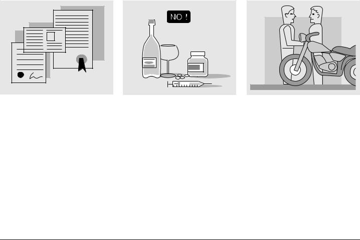
To drive the vehicle it is necessary to be in possession of all the requirements prescribed by law (driving licence, minimum age, psychophysical ability, insurance, state taxes, vehicle registration, number plate, etc.).
Gradually get to know the vehicle by driving it first in areas with low traffic and/or private areas.
The use of medicins, alcohol and drugs or psychotropic substances notably increases the risk of accidents.
Be sure that you are in good psychophysical conditions and fit for driving and pay particular attention to physical weariness and drowsiness.
Most road accidents are caused by the driver’s lack of experience.
NEVER lend the vehicle to beginners and, in any case, make sure that the driver has all the requirements for driving.
6 use and maintenance Gulliver 50
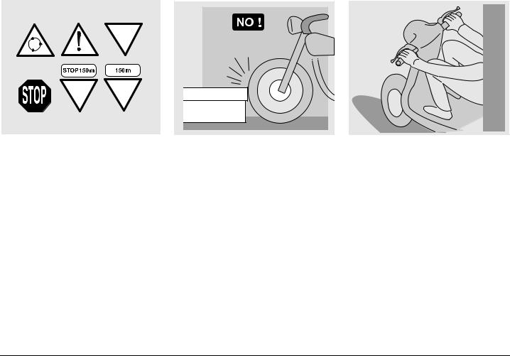
Rigorously observe all road signs and national and local road regulations.
Avoid abrupt movements that can be dangerous for yourself and other people (for example: rearing up on the back wheel, speeding, etc.), and give due consideration to the road surface, visibility and other driving conditions.
Avoid obstacles that could damage the vehicle or make you lose control.
Avoid riding in the slipstream created by preceding vehicles in order to increase your speed.
Always drive with both hands on the handlebars and both feet on the footrests, in the correct driving posture.
Avoid standing up or stretching your limbs while driving.
use and maintenance Gulliver 50 7
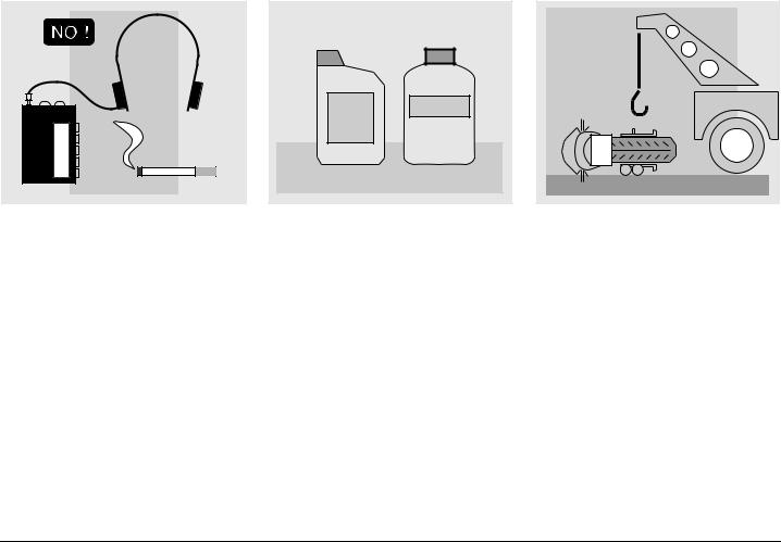
The driver should pay attention and avoid distractions caused by people, things and movements (never smoke, eat, drink, read, etc.) while driving.
COOLER |
OIL |
Use only the vehicle’s specific fuels and lubricants indicated in the "Lubricant Chart"; check all oil, fuel and coolant levels regularly.
If the vehicle has been involved in an accident, make sure that no damage has occurred to the control levers, pipes, wires, braking system and vital parts.
If necessary, have the vehicle inspected by an aprilia Official Dealer, who should carefully check the frame, handlebars, suspensions, safety parts and all the devices that you cannot check by yourself.
Always remember to report any malfunction to the technicians to help them in their work.
Never use the vehicle when the amount of damage it has suffered endangers your safety.
8 use and maintenance Gulliver 50

ONLY ORIGINALS
A12 345
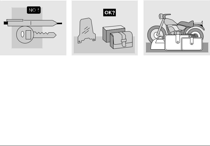
Never change the position, the inclination or the colour of: number plate, direction indicators, lights and horns.
Any modification of the engine or of other members which is aimed at increasing the speed or the power of the vehicle is prohibited by the law; in fact, any modification resulting in an increase of the maximum speed or of the engine displacement would change the scooter into a motorcycle, which implies the following obligations for the owner:
–new homologation;
–new registration;
–appropriate driving license.
Further, said modifications cause the loss of the insurance cover, since insurance policies expressly prohibit to make technical changes aimed at increasing the vehicle performance levels.
For the reasons stated above, the failure to comply with the tampering prohibition is punished by law with apposite sanctions (including the confiscation of the vehicle), which, according to the case, can be combined with the sanctions provided for not using the crash helmet and/or the number plate, for the violation of fiscal obligations (ownership tax) and with penal sanctions provided for using the vehicle without driving license.
Never race with other vehicles.
Avoid off-road driving.
#,/4().' |
Before starting, always wear a correctly fastened crash helmet. Make sure that it is homologated, in good shape, of the right size and that the visor is clean.
Wear protective clothing, preferably in light and/or reflecting colours. In this way you will make yourself more visible to the other drivers, thus notably reducing the risk of being knocked down, and you will be more protected in case of fall. This clothing should be very tight-fitting and fastened at the wrists and ankles. Strings, belts and ties should not be hanging loose; prevent these and other objects from interfering with driving by getting entangled with moving parts or driving mechanisms.
use and maintenance Gulliver 50 9
Do not keep objects that can be dangerous in case of fall, for example pointed objects like keys, pens, glass vials etc. in your pockets (the same recommendations also apply to passengers).
!##%33/2)%3
The owner of the vehicle is responsible for the choice, installation and use of any accessory.
Avoid installing accessories that cover horns or lights or that could impair their functions, limit the suspension stroke and the steering angle, hamper the operation of the controls and reduce the distance from the ground and the angle of inclination in turns. Avoid using accessories that hamper access to the controls, since this can prolong reaction times during an emergency. Large fairings and windscreens assembled on the vehicle can produce aerodynamic forces capable of compromising the stability of the vehicle while driving.
Make sure that the equipment is well fastened to the vehicle and not dangerous during driving.
Do not install electrical devices and do not modify those already existing to avoid electrical overloads, because the vehicle could suddenly stop or there could be a dangerous current shortage in the horn and in the lights. aprilia recommends the use of aprilia genuine accessories.
,/!$
Be careful and moderate when loading your luggage. Keep any luggage loaded as close as possible to the centre of the vehicle and distribute the load uniformly on both sides, in order to reduce imbalance to the minimum.
Furthermore, make sure that the load is firmly secured to the vehicle, especially during long trips.
10 use and maintenance Gulliver 50
KG! |
Avoid hanging bulky, heavy and/or dangerous objects on the handlebars, mudguards and forks, because the vehicle might respond more slowly in turns and its manoeuvrability could be unavoidably impaired.
Do not place bags that are too bulky on the vehicle sides and do not ride with the crash helmet hanging from its string, because it could hit people or obstacles making you lose control of the vehicle.
Do not carry any bag if it is not tightly secured to the vehicle.
Do not carry bags which protrude too much from the luggage-rack or which cover the lights, horn or indicators.
Do not carry animals or children on the glove compartment or on the luggage-rack.
Do not exceed the maximum load allowed for each side-bag.
When the vehicle is overloaded, its stability and its manoeuvrability can be compromised.
use and maintenance Gulliver 50 11
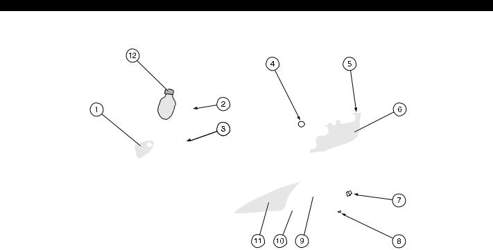
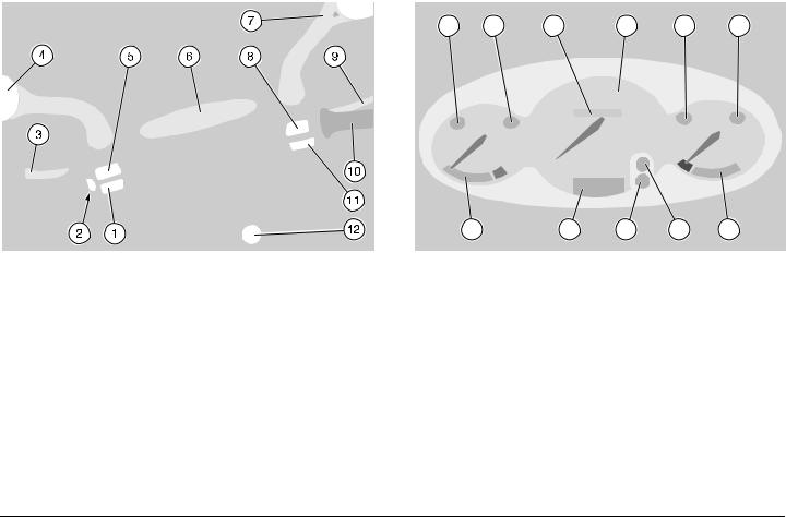
 !22!.'%-%.4 /& 4(% -!). %,%-%.43
|
|
|
|
|
|
+%9 |
|
|
|
||
1) |
Fuel tank flap |
7) |
Transmission oil filler cap |
||
2) |
Glove / tool kit compartment |
8) |
Trasmission oil drain plug |
||
3) |
Bag hook |
9) |
Kick starter |
||
4) |
Saddle lock |
10) |
Kickstand |
||
5) |
Mixer oil plug |
11) |
Left lower cover of the rear part of the |
||
6) |
Mixer oil tank |
|
fairing |
||
|
|
|
12) |
Coolant expansion tank plug 1 |
|
12 use and maintenance Gulliver 50
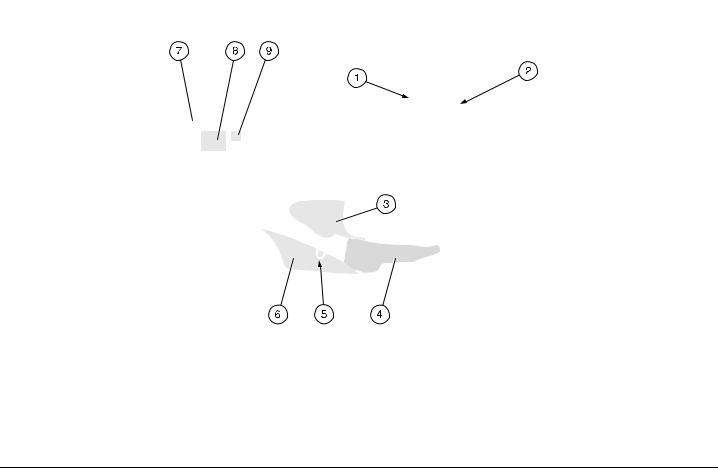
|
|
|
|
|
+%9 |
|
|
||
1) |
Ignition/steering lock switch |
6) |
Right lower cover of the rear part of the |
|
2) |
Horn |
|
fairing |
|
3) |
Inspection cover |
7) |
Rear hood |
|
4) |
Fuel tank |
8) |
Battery |
|
5) |
Anti-theft hook |
9) |
Fuse carrier |
|
use and maintenance Gulliver 50 13
!22!.'%-%.4 /& 4(% ).3425-%.43 |
|
).3425-%.43 !.$ ).$)#!4/23 |
|
|
|||
|
1 |
2 |
3 |
4 |
5 |
6 |
|
|
|
|
11 |
10 |
9 |
8 |
7 |
+%9 |
+%9 |
|
|
|
|
||
1) |
Horn push button (f) |
1) |
Green direction indicator warning light (c ) |
|
|||
2) |
Cold start lever (e) |
2) |
Red mixer oil reserve warning light ( j) |
|
|
||
3) |
Rear brake lever |
3) |
Odometer |
|
|
|
|
4) |
Left rear-view mirror |
4) |
Speedometer |
|
|
|
|
5) |
Direction indicator switch (c) |
5) |
Green low beam warning light (b) |
|
|
||
6) |
Instruments and indicators |
5) |
Blue high beam warning light (a) J- % |
|
|||
7) |
Right rear-view mirror |
6) |
Amber low fuel warning light (g) |
|
|
|
|
8) |
Light switch (b - p - •) |
7) |
Fuel level indicator (g) |
|
|
|
|
8) |
Light switch (a - b - • ) J- % |
8)9) |
Digital clock function and setting push button |
|
|||
9) |
Front brake lever |
10) |
Digital clock |
|
|
|
|
10) |
Throttle grip (r) |
11) |
Coolant temperature indicator 1(h) |
|
|
||
11)Start push button
12)Ignition switch/steering lock (n - m - s)
14 use and maintenance Gulliver 50

).3425-%.4 !.$ ).$)#!4/2 4!",%
DESCRIPTION |
|
FUNCTION |
|
|
|
Direction indicator warning light |
c |
It blinks when the direction indicators are on. |
|
|
|
|
|
It comes on every time the key is turned to position "n" and the start push button |
|
|
"r" is pressed, thus checking the proper functioning of the lamp. |
|
|
If during the starting the lamp does not turn on, it must be replaced. |
Mixer oil reserve warning light |
j |
If the warning light comes on and does not go off after releasing |
|
|
the start push button "r", or comes on during the normal running |
|
|
aof the engine, this means that the oil level is in reserve. In this case, |
|
|
provide for topping up, in order to avoid serious damages to the engine, |
|
|
see p. 24 (MIXER OIL TANK). |
|
|
|
Total kilometres odometer |
|
It indicates the total number of kilometres covered. |
|
|
|
Speedometer |
|
It indicates the driving speed. |
|
|
|
Low beam warning light |
b |
It comes on when the headlight is on "low beam" position. |
|
|
|
High beam warning light J- % |
a |
It comes on when the headlight is on. |
|
|
|
Low fuel warning light |
g |
It comes on when the quantity of fuel left in the tank is about 1.5 L. |
|
|
|
Fuel level indicator |
g |
It indicates the approximate fuel level in the tank. |
|
|
|
|
|
It indicates the approximate temperature of the coolant in the engine. |
|
|
When the pointer starts moving beyond the "MIN" level, the temperature is suffi- |
|
|
cient for driving the vehicle. The normal running temperature range is indicated |
Coolant temperature indicator 1 |
h |
by the white area of the scale. |
|
|
If the pointer reaches the red area, stop the engine and check the coolant level, |
|
|
see p. 24 (COOLANT). |
|
|
If the maximum allowed temperature is exceeded, the engine may be seriously |
|
|
damaged. |
|
|
|
Digital clock |
|
Hour, date and seconds can be shown in the display, see p. 19 (DIGITAL |
|
CLOCK). |
|
|
|
|
|
|
|
use and maintenance Gulliver 50 15
-!). ).$%0%.$%.4 #/.42/,3
3
2 1
#/.42/,3 /. 4(% ,%&4 3)$% /& 4(% (!.$,%"!23
cThe electrical parts work only when the ignition key is in position "n".
1)HORN PUSH BUTTON (f)
The horn is activated when the push button is pressed.
2)COLD START LEVER (e)
The starter for the cold start of the engine is operated by rotating the cold start lever downwards.
To disconnect the starter, it is necessary to bring the lever back to its initial position.
3)DIRECTION INDICATOR SWITCH (c)
To indicate the turn to the left, move the switch to the left; to indicate the turn to the right, move the switch to the right.
To turn off the direction indicator, press the switch.
16 use and maintenance Gulliver 50
#/.42/,3 /. 4(% 2)'(4 3)$% /& 4(% (!.$,%"!23
cThe electrical parts work only when the ignition key is in position "n".
1)HEADLIGHT SWITCH ( b - p - •)
When the ignition key is in position "n" and the headlight switch is in position "•", the lights are off; when the switch is in
position " p", the parking lights are on (in the versions F- O the low beam is on); when the switch is in position "b", the low beam is on.
2)START PUSH BUTTON ( r )
When the start push button is pressed and at the same time one of the brake levers (front or rear) is operated, the starter makes the engine run.
For the starting, see p. 32 (STARTING).
3)HEADLIGHT SWITCH (a - b - •) J- %
When the ignition key is in position "n" and the headlight switch is in position "•", the lights are off; when the switch is in position "b", the low beam and the parking lights are on; when the switch is in position "a", the high beam and the parking lights are on.
use and maintenance Gulliver 50 17
)'.)4)/. 37)4#(
The ignition switch is positioned on the right side, near the steering column (1).
cThe key (1) operates the ignition switch/steering lock, the glove compartment, the saddle lock and the
fuel tank flap.
Two keys are supplied together with the vehicle (one spare key).
34%%2).' ,/#+
Never turn the key to position "s" ain running conditions, in order to avoid losing control of the vehi-
cle.
OPERATION
To lock the steering, turn the handlebars leftwards completely.
With the key (1) in position "m", press the key, release it and turn it to position "s". Extract the key.
POSITION |
FUNCTION |
KEY |
|
|
REMOVAL |
|
|
|
|
The steering is |
It is |
s |
locked. |
possible to |
It is neither |
remove the |
|
possible to |
key. |
|
Steering |
start the |
|
lock |
|
|
engine, nor to |
|
|
|
|
|
|
switch on the |
|
|
lights. |
|
|
|
|
|
Neither the |
It is |
m |
engine, nor the |
possible to |
lights can be |
remove the |
|
|
switched on. |
key. |
|
|
|
n |
The engine |
It is not |
and the lights |
possible to |
|
can be |
remove the |
|
|
switched on. |
key. |
|
|
|
18 use and maintenance Gulliver 50
!58),)!29 %15)0-%.4
3%44).' 4(% #,/#+
Display:
Normal display: hours and minutes.
Date display: press the push button (1) once to display month and day.
Second display: press the push button
(1) twice to display the seconds.
Setting:
Press the push button (2) once: date and time will be displayed alternately.
Month: press the push button (2) again and the month will be displayed on the left (the rest disappears).
Press the push button (1) to set the desired month.
Day: press the push button (2) again and the day will be displayed on the right. Press the push button (1) to set the desired day.
Time: press the push button (2) again and the time will be displayed on the left with letter "A" or "P" ("A"=AM, "P"=PM). Press the push button (1) to set the desired time.
Minutes: press the push button (2) again and the minutes will be displayed on the right.
Press the push button (1) to set the desired minutes.
Now the clock is set. Press the push button (2) again to return to normal functioning.
#(!.').' 4(% #,/#+ #%,,
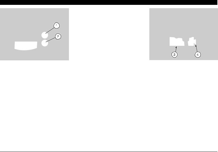
Remove the front handlebar cover, see p. 49 (REMOVING THE FRONT HANDLEBAR COVER).
Remove the clock support (3) from the rear of dashboard, acting on the snapcoupling (4).
Extract the clock and change the cell.
use and maintenance Gulliver 50 19
|
|
Do not drive with the rear hood |
|
|
aopen. |
|
|
Before lowering and locking the |
|
|
csaddle, make sure that you have |
|
|
not left the key in the crash hel- |
|
|
met/glove compartment. |
|
|
To lock the saddle, lower and press it |
|
|
(without exerting too much pressure), |
|
|
thus making the lock snap shut. |
|
|
|
5.,/#+).' ,/#+).' |
Before leaving, make sure that |
|
4(% 3!$$,% |
athe saddle is properly locked. |
|
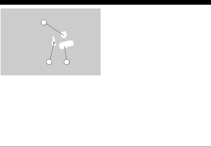
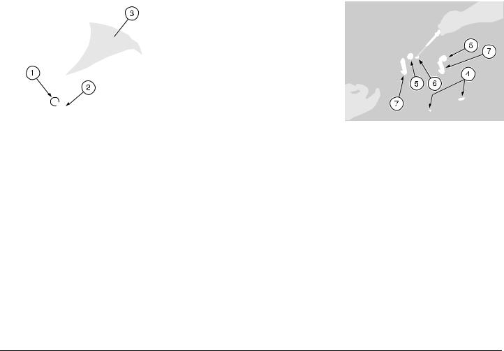
To unlock and raise the saddle, proceed as follows:
Insert the key (2) in the saddle lock (1).
Turn the key (2) clockwise and raise the saddle.
Once the saddle has been raised, it is possible to raise also the rear hood (3).
Before lowering the saddle, close the rear hood (3) and make sure that it does not remain raised, since in this position it would make it impossible to lock the saddle.
3!$$,% ,/#+).' !$*534-%.4
If it is difficult to lock the saddle or if the saddle does not remain locked, proceed as follows:
Make sure the the two closing (4) and guide (5) seats are open and that nothing hinders the lowering of the saddle.
If no obstacle hinders the closing or the opening of the saddle, adjust the closing hooks (7), acting with the apposite key on the screw (6) positioned under the saddle between the two closing hooks
(7).
After carrying out the adjustment, lower the saddle and press it in order to verify the closing and the proper locking/unlocking of the saddle.
20 use and maintenance Gulliver 50
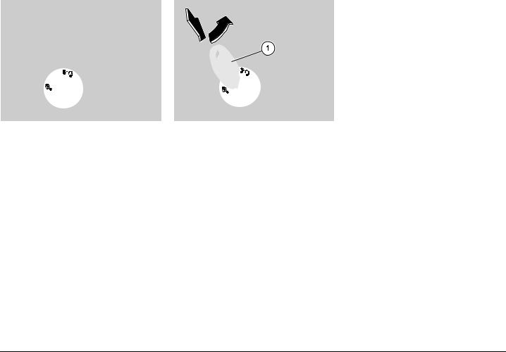
#2!3( (%,-%4 ',/6% #/-0!24-%.4
Thanks to the crash helmet/glove compartment, you no longer have to carry the crash helmet or other objects with you every time you park the vehicle.
The compartment is positioned under the saddle; to reach it:
raise the saddle (1) and if necessary the rear hood (2), see p. 20 (UNLOCKING/LOCKING THE SADDLE).
Do not load the crash hel- amet/glove compartment too
much.
Maximum allowed weight: 2.5 kg.
42!.30/24).' #5-"%23/-% /"*%#43
Respect the regulations in force aas to the vehicle load and the
transport of objects.
To transport cumbersome objects which hinder the closing of the saddle or which are dangerous when hanging from the bag hook, proceed as follows:
Raise the saddle (1) and the rear hood
(2).
Unscrew and remove the knob (3).
Remove the rear hood (2).
Put the object/objects in the crash helmet compartment, close the rear hood support (4), letting the part of the load that is too big protrude out of the compartment itself.
Lower and lock the saddle.
Before departure, make sure that athe saddle is properly locked and that the objects you intend to transport are well positioned inside
the compartment.
use and maintenance Gulliver 50 21
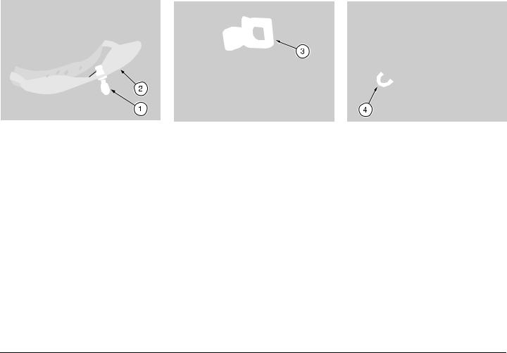
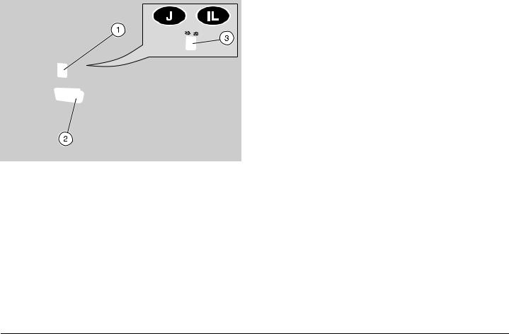
',/6% 4//, +)4 #/-0!24-%.4
It is placed under the handlebar, on the inner part of the shield.
To reach it:
Introduce the ignition key (1) in the lock.
Turn the key (1) clockwise, pull it and open the door (2).
The tool kit includes: no. 1 tool case
no. 1 25 mm spark plug spanner no. 1 tube for spark plug spanner no. 1 8/10 mm socket spanner
no. 1 double-ended, cross-/cut-headed screwdriver
no. 1 screwdriver handle
no. 1 4 mm hexagon spanner
Before locking the door (2), amake sure that you have not left the key in the glove/tool kit com-
partment.
To lock the door (2), raise and press it. It is not necessary to use the key.
Maximum allowed weight: 1.5 kg.
"!' (//+
Do not hang excessively bulky abags or parcels to the hook, as this could seriously compromise the manoeuvrability of the vehicle or the
movement of your feet.
The bag hook (3) is placed frontally in inner part of the shield.
Maximum allowed weight: 1.5 kg.
!.4) 4(%&4 (//+
The anti-theft hook (4) is placed on the right side of the vehicle, under the footrest.
To prevent the stealing of the vehicle, fix it to a firm support by means of a chain and a lock (or equivalent systems), which are easily available on the market.
Do not use the hook either to lift aor to tow the vehicle or for other purposes, since it has been designed only to secure the vehicle once
it has been parked.
22 use and maintenance Gulliver 50
-!). #/-0/.%.43
&5%,
The fuel used for internal com- abustion engines is extremely inflammable and in particular con-
ditions it can become explosive.
It is important to carry out the refuelling and the maintenance operations in a well-ventilated area, with the engine off.
Do not smoke while refuelling or near fuel vapours, in any case avoid any contact with free flames, sparks and any other heat source to prevent the fuel from catching fire or from exploding.
Further, prevent fuel from flowing out of the fuel filler, as it could catch fire when getting in contact with the red-hot surfaces of the engine.
In case some fuel has accidentally been spilt, make sure that the area has completely dried and before starting the vehicle verify that there is no fuel inside the fuel filler neck.
Since petrol expands under the heat of the sun and due to the effects of sun radiation, never fill the tank to the brim.
Screw the cap up carefully after refuelling.
Avoid any contact of the fuel with the skin and the inhalation of vapours; do not swallow fuel or pour it from a receptacle into another by means of a tube.
KEEP AWAY FROM CHILDREN
Use only premium grade petrol, (4 Stars U) in conformity with the DIN 51600 standard, min. O.N. 98 (N.O.R.M.) and 88 (N.O.M.M.).
FUEL TANK CAPACITY (reserve included): 7 L
TANK RESERVE: 1.5 L
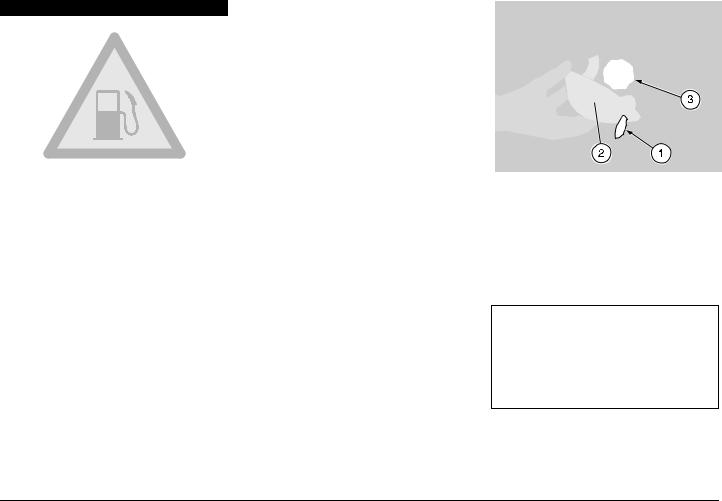
To reach the fuel tank cap, proceed as follows:
Insert the key (1) in the fuel flap lock (2) (on the left side, under the front direction indicator).
Turn the key anticlockwise, pull it and open the fuel flap.
Unscrew the tank cap (3).
2
ONLY FOR THE CATALYTIC VERSION
Use only unleaded petrol, in conformity with the DIN 51607 standard, min. O.N. 95 (N.O.R.M.) and 85 (N.O.M.M.).
use and maintenance Gulliver 50 23
 Loading...