


Xserve (Late 2006)
Rear ID Tab
Replacement Instructions
Follow the instructions in this document carefully. Failure to follow these instructions could damage your equipment and void its warranty.
Online instructions are available at http://www.apple.com/support/diy/.
Working Safely Inside the Xserve
Always touch the Xserve enclosure to discharge static electricity before you touch any components inside the Xserve. To avoid generating static electricity, do not walk around the room until you have finished working inside the server and have replaced the cover.To minimize the possibility of damage due to static discharge, wear an antistatic wrist strap while you work inside the Xserve.
Warning: Always shut down the Xserve and disconnect the power cords before opening it to avoid damaging its internal components or the components you are installing. Don’t open the server while it is turned on. Even after you shut down the Xserve, its internal components can be very hot. Let it cool before you open it.
Tools Required
The following tools are required for this procedure:
•Phillips #1 screwdriver
•Antistatic wrist strap (if available)
•2 thermal grease syringes for replacing processor heat sinks (supplied with the replacement part)
•2 alcohol wipes for cleaning processors and heat sinks (supplied with the replacement part)
073-1112 Rev. A
Removing the Xserve from a Rack
1.Alert users that the server will be unavailable for a period of time.
2.Shut down the Xserve (see the Xserve User’s Guide for help) and then wait to let the Xserve internal components cool.
Warning: Always shut down the Xserve before opening it to avoid damaging its internal components or the components you want to install or remove. Don’t open the Xserve or try to install or remove items inside while it is turned on. Even after you shut down the Xserve, its internal components can be very hot. Let it cool down for 5 to 10 minutes before you open it.
3.Unplug all cables from the Xserve.
Note: If you have trouble releasing a cable from the back panel, try using a small screwdriver or other flat tool to depress the tab on the cable connector.
4.To avoid inadvertently unlatching a drive module during handling, use the enclosure key to lock the enclosure lock on the front panel.
5.Touch the server’s metal case to discharge any static electricity.
6.Loosen the thumbscrews at both ends of the front panel.
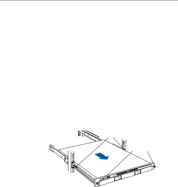
7.Grasp the thumbscrews and pull the Xserve forward until the safety latches engage (about halfway out of the rack).
Latches
Thumbscrews
8.When the safety latches engage, grip the Xserve where it emerges from the rack, press down on the latch tabs with your thumbs, and slide the Xserve the rest of the way out of the rack rails.
9.Set the Xserve on a flat surface and unlock it.
Xserve (Late 2006) Rear ID Tab Replacement Instructions

Opening the Xserve
Loosen the thumbscrews at the back of the top cover and slide the cover back and up to remove it. If you have difficulty removing the cover, check the enclosure lock on the front panel.
Warning: Even after you shut down the Xserve, its internal components can be very hot. Let it cool before you open it.
Important: To minimize the possibility of damage to Xserve components due to static discharge, wear an antistatic wrist strap, if possible, while you work inside the Xserve.
Slide the cover back and lift it off.
Unscrew the two captive thumbscrews.
Removing the Installed Rear ID Tab
Before removing the installed rear ID tab, remove the following parts:
•Both power supplies
•PCI riser cards and any expansion cards in both slots (if installed)
•Airflow duct
•Fan array
•Backplane-to-logic board I/O cable
•Both processor heat sinks
•Logic board
Power Supplies
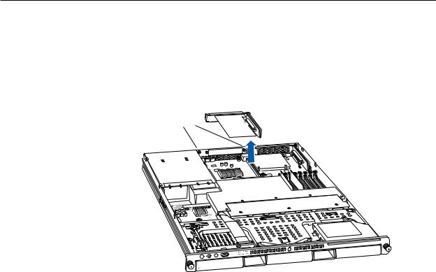
1.Pull the handle to release the first power supply and slide it out of the bay.
Pull the handle to unlatch the power supply and remove it.
2.Repeat for the second power supply, if installed.
Xserve (Late 2006) Rear ID Tab Replacement Instructions
PCI Riser Cards and Expansion Cards
1.Loosen the two captive screws that secure the riser bracket in slot 1 to the back panel.
2.Carefully pull up on the bracket and riser, with the expansion card still attached, to disconnect the riser from the logic board.
Captive screws
3.Tilt the expansion card up so that its port clears the enclosure, and remove the card from the Xserve.
4.Repeat for the riser card in slot 2.
Xserve (Late 2006) Rear ID Tab Replacement Instructions
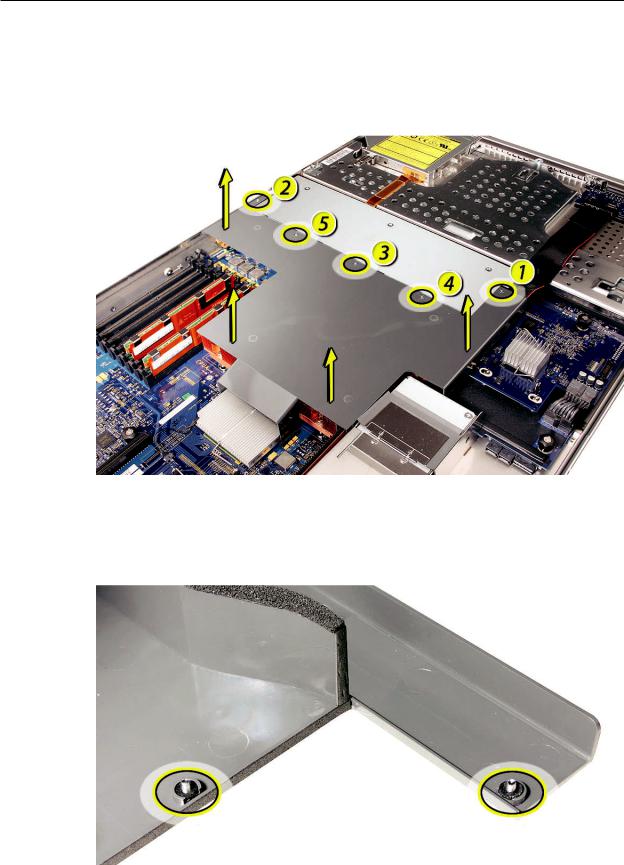
Airflow Duct
1.Loosen the five Phillips screws that fasten the airflow duct to the fan array.
2.Pull up on either side of the airflow duct, and lift it straight up and out of the Xserve.
Caution: Try not to completely remove the screws from the airflow duct.Tiny black rubber washers hold these screws captive on the underside of the airflow duct. If the screws are completely removed, these rubber washers can easily fall into the enclosure and become lost.
Xserve (Late 2006) Rear ID Tab Replacement Instructions
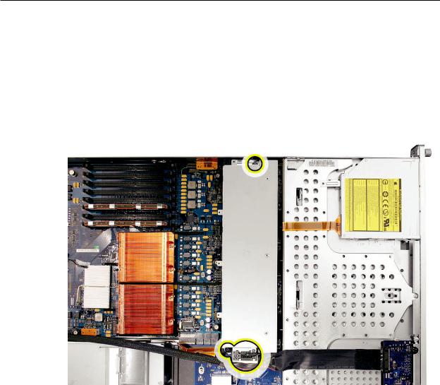
FanArray
1.Loosen the two thumbscrews that secure the fan array to the enclosure. Note: The thumbscrews are captive; you cannot remove them.
2.Lift the fan array to remove it from the Xserve.
Note: You may need to move the front panel cable slightly out of the way of the fan array power connector during removal or replacement. Be careful not to pinch the front panel board cable between the fan array and any other surface inside.
Xserve (Late 2006) Rear ID Tab Replacement Instructions

Note: You may encounter some resistance around the fan array power connector during removal. If so, carefully rotate the fan array as shown to disconnect it from the power distribution board below, and then lift the fan array out of the computer.
Backplane-to-Logic Board I/O Cable
1.Disconnect the backplane-to-logic board cable from the logic board.
Xserve (Late 2006) Rear ID Tab Replacement Instructions
 Loading...