


 Loading...
Service Source
Mac Pro (Early 2008)
Updated: 23 April 2008
© 2008 Apple Inc. All rights reserved.

Apple Inc.
© 2008 Apple Inc. All rights reserved.
Under the copyright laws, this document may not be copied, in whole or in part, without the written consent of Apple.
Every effort has been made to ensure that the information in this document is accurate. Apple is not responsible for printing or clerical errors.
Apple
1 Infinite Loop
Cupertino, CA 95014-2084 USA
+ 1 408 996 1010 www.apple.com
Apple, the Apple logo, and Mac Pro are trademarks of Apple Inc., registered in the U.S. and other countries.
ii

Mac Pro (Early 2008)
Contents
Basics
Overview 7
Identifying Mac Pro (Early 2008) Computers 8
Serial Number Location 8
Special Handling Instructions for Dual 3.2 GHz Configuration 9
Handling Instructions |
9 |
Safety and First Aid Guidelines 10 |
|
Disposal Instructions |
11 |
Take Apart
General Information 13
Orientation 13 Tools 13
Parts Requiring Enclosure Replacement 13 Note on Illustrations 13
Opening the Computer 14 Hard Drives 16
Optical Drive Carrier and Optical Drives 19 Memory (FB-DIMMs) and Memory Riser Cards 23 PCI Express/Graphics Card 27
Power Supply 32 Power Supply Fan 36 AirPort Extreme Card 41 Bluetooth Card 44 Battery 46
Processor Heatsink Cover 48
iii

Front Fan Assembly 51
Mac Pro RAID Card and Battery 56 Memory Cage with Rear Fan 62 Northbridge Heatsink 68
Processor Heatsinks for 2.8 and 3.0 GHz Processors 71 Processor Heatsinks for 3.2 GHz Processors 78
Processors, 2.8 and 3.0 GHz 87 |
|
|||||
Processors, 3.2 GHz |
92 |
|
|
|||
Speaker Assembly |
97 |
|
|
|||
USB Cable |
100 |
|
|
|
|
|
Logic Board |
102 |
|
|
|
|
|
Front Panel Board |
110 |
|
|
|||
Power Button |
114 |
|
|
|
|
|
AirPort Antenna Board with Cables |
118 |
|||||
Optical Drive Power Cable |
122 |
|
||||
Optical Drive Data (Ribbon) Cable |
125 |
|||||
Ambient Board |
127 |
|
|
|
||
Ambient Board Cable |
129 |
|
|
|||
Bluetooth Antenna Board and Cable |
131 |
|||||
Hard Drive Cable Harness |
134 |
|
||||
Hard Drive Temperature Sensor Cable 136 |
||||||
Hard Drive Temperature Sensor 138 |
||||||
Power Cable Harness |
141 |
|
|
|||
Troubleshooting
General Information 147
Memory 147
PCI Express Cards 149
Internal Cabling Matrix 149
iv

Thermal Calibration 151 |
|
Resetting the Logic Board |
152 |
Power-On Self Test:RAM and Processor Verification 153 |
|
Diagnostic LEDs 154 |
|
Power Supply Verification |
159 |
Mac Pro Firmware Updates |
159 |
Processor Heatsink and Processor Visual Inspection Instructions 161 |
|
Symptom Charts |
164 |
How to Use the Symptom Charts 164 |
|
Startup Failures |
164 |
Fans 167 |
|
AirPort Extreme Card 168 |
|
Bluetooth Card |
169 |
Other Failures |
169 |
Upgrades
AirPort Extreme Card 173
PCI Express/Graphics Card 176
Views
Exploded Views 181
External Views 183
Screw Matrix 185
v
Service Source
Basics
Mac Pro (Early 2008)
© 2008 Apple Inc. All rights reserved.
 Overview
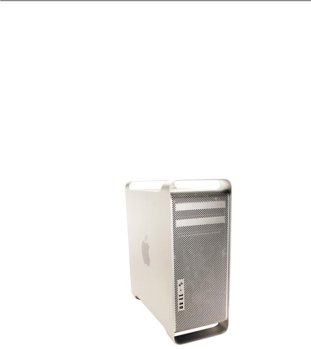
The Mac Pro (Early 2008) computer features single and dual quad-core Intel 2.8 GHz processors and dual quad-core Intel 3.0 and 3.2 GHz processors. New CTO options include a 1 TB SATA hard drive and a 300 GB SAS drive.
Note: The 3.2 GHz configuration of the Mac Pro (Early 2008) computer uses a special coating on the processor heatsink and processor as was used on the Mac Pro (8x) processor heatsink and processor.The other 2.8 and 3.0 configurations of the Mac Pro (Early 2008) do not use this coating.
Mac Pro (Early 2008)) Basics 7
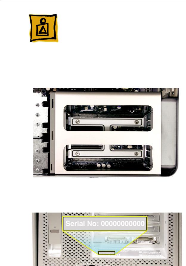
Identifying Mac Pro (Early
2008) Computers
To identify a Mac Pro (Early 2008) computer, check the configuration code on the computer’s configuration label, which is located on the computer’s back panel directly below the video ports.
See the following section “Serial Number Location.”
One other quick way to identify the computer is to open the side panel and inspect the memory cage. The Mac Pro (Early 2008) memory cage has a cross bar and looks like the following:
Serial Number Location
The Mac Pro (Early 2008) serial number is located on the configuration label, directly below the configuration description.
Mac Pro (Early 2008)) Basics 8

Special Handling Instructions for Dual 3.2 GHz Configuration
The dual 3.2 GHz configuration of the Mac Pro (Early 2008) uses a special coating on the processor heatsink and processor to manage the temperature in the computer. To ensure proper handling and disposal of this material, please read the following information.
Important: These instructions apply only to the dual 3.2 GHz configuration.
Handling Instructions
Use these guidelines when handling the Mac Pro (Early 2008) processor heatsink and processor:
General
•Wear disposable nitrile or latex gloves when handling the processor heatsink and processor.
•Avoid touching the silver coating on the underside of the heatsink and the top of the processor.
•Use care when removing the heatsink from the computer. As much as possible, lift the heatsink straight up off the processor.
•Use care when removing the processor from the logic board. Lift the processor out of the processor holder by inserting a finger or flatblade screwdriver in the notch at the front of the holder. Hold the processor only by the edges.
•When installing a replacement heatsink or processor, remove the protective cover from the new heatsink or processor and transfer it to the defective heatsink or processor before packaging it for return to Apple.
Timing
•When removing or replacing the heatsink and/or processor, do not allow the heatsink to be separated from the processor for more than 30 minutes. The silver coating on the heatsink and processor degrades with exposure to air; more than 30 minutes exposure could result in damage to the computer and a repeat, multi-part repair. Reassemble the computer while waiting for any new parts to arrive.
•When installing a new logic board, use care in transferring the heatsinks and processors to the new board. Do not allow the heatsinks and processors to be separated from the board or from each other for more than 30 minutes. Reassemble the computer while waiting for a new logic board to arrive.
Visual Inspection
•Always make a visual inspection of a new processor or heatsink before installing it in the computer.
•Always make a visual inspection of both existing processors and heatsinks before transferring them to a new logic board.
Mac Pro (Early 2008)) Basics 9

•See “Processor Heatsink and Processor Visual Inspection Instructions” in the Troubleshooting chapter for more information.
Krytox Thermal Grease
•To ensure a proper seal between the heatsink and processor, a bead of Krytox grease rims the gasket on the underside of the heatsink. Replacement heatsinks come with the grease already applied.
•Use the following guidelines for when to reapply Krytox grease to the heatsink. (Refer to “Processor Heatsinks for 3.2 GHz Processors” in the Take Apart chapter for detailed instructions on how to apply or clean off the grease.)
-- In most cases, you do not need to reapply Krytox grease when installing a new processor or when transferring processors and heatsinks to a replacement logic board.
-- If you are installing a new heatsink , remove any residual grease from the outer edges of the processor. Do not apply new grease to the heatsink or processor, as the heatsink comes with the full capacity of grease applied.
For more detailed information, refer to “Processor Heatsinks for 3.2 GHz Processors” and “Processors, 3.2 GHZ” in the Take Apart chapter.
Safety and First Aid Guidelines
Below is a summary of safety and first aid measures for exposure to the coating on the processor heatsink and processor or the Krytox grease used in sealing the processor heatsink to the processor. For complete instructions, refer to the specific Material Safety Data Sheets (MSDS) included with the replacement parts.
Safety
Avoid contact with eyes.
Avoid contact with skin.
Wash thoroughly after handling.
Do not store or consume food, drink, or tobacco in areas where they may become contaminated with the material.
First Aid
Eyes: Immediately flush with plenty of water. If wearing contact lenses, after initial flushing, remove contact lenses and continue to flush for 15 minutes. Have eyes examined by a medical professional if irritation persists.
Skin: Wash skin with soap and running water.The recommended flushing is 15 minutes if pain or irritation occurs. Remove and wash contaminated clothing. Seek medical attention if irritation or redness develops.
Inhalation: Remove to fresh air. If not breathing, give artificial respiration. If breathing is difficult, give oxygen. Call a physician.
Mac Pro (Early 2008)) Basics 10
Ingestion: Do not induce vomiting. Contaminated individual should immediately be given two glasses of water. Never give anything by mouth to someone who is unconscious, having convulsions, or unable to swallow. Call a physician.
Disposal Instructions
Place all disposable materials used in removing or replacing a processor heatsink or processor inside the resealable plastic bag included with the replacement module. (Disposable materials include such items as protective gloves, alcohol wipes, lint-free cleaning cloths, Krytox grease and syringe, and heatsink gasket.) Pack this bag along with the failed module in the box that the replacement module came in, and return the box to Apple.
Mac Pro (Early 2008)) Basics 11
Service Source
Take Apart
Mac Pro (Early 2008)
© 2008 Apple Inc. All rights reserved.

 General Information
Orientation
For most take-apart procedures, it is recommended that you lay the computer on its side before removing or installing the part. For proper operation, however, Apple recommends that the unit be run in the upright position. The computer should never be operated on its side with the access panel facing down.
Tools
The following tools are required to service all configurations of the computer:
•Long-handled magnetized Phillips #1 screwdriver
•Long-handled magnetized 3 mm flathead hex screwdriver
•Short-handled, magnetized 2.5 mm hex wrench
•Flat-blade screwdriver
•Magnetized jewelers Phillips #1 screwdriver
•Magnetized jeweler’s Phillips #0 screwdriver
•Jeweler’s flat-blade screwdriver
•Needlenose pliers
•Scissors or wire cutters
•Nylon probe tool (black stick)
•Thermal grease kit (Apple part number 076-1258)
•Tape (for temporarily holding cables out of the way)
•Small mirror (for seeing small boards inside the enclosure)
•Soft cloth (for protecting the enclosure from scratches)
Parts Requiring Enclosure Replacement
The following are not separate, orderable parts. To replace them, you must replace the enclosure.
•Media shelf
•Rear panel latch
Note on Illustrations
Because a pre-production model was used for the illustrations in this manual, you may notice small differences between the image pictured and the computer you are servicing.
Mac Pro (Early 2008) Take Apart — General Information 13

 Opening the Computer
Tools
No tools are required for this procedure.
Preliminary Steps
1.Shut down the computer.
Warning: Always shut down the computer before opening it to avoid damaging its internal components or the components you are installing. Do not open the computer or attempt to install items inside it while it is on.
2.Wait 5 to 10 minutes to allow the computer’s internal components to cool.
Warning: After you shut down the system, the internal components can be very hot. You must let the computer cool down before continuing.
3.Unplug all external cables from the computer except the power cord.
4.Touch the metal PCI access covers on the back of the computer to discharge any static electricity from your body.
Important: Always discharge static before you touch any parts or install any components inside the computer. To avoid generating static electricity, do not walk around the room until you have finished working and closed the computer.
5.Unplug the power cord.
Warning: To avoid damaging its internal components or the components you want to install, always unplug the computer before attempting any take-apart procedure.
6.Put on an ESD wrist strap.
Mac Pro (Early 2008) — Opening the Computer 14
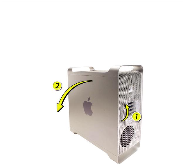
Procedure
1.Hold the side access panel and lift the latch on the back of the computer.
Warning: The edges of the access panel and the enclosure can be sharp. Be very careful when handling them.
2.Remove the access panel and place it on a flat surface covered by a soft, clean cloth.
Replacement Note: Make sure the latch is in the up position before replacing the access panel. If the latch is down, the access panel will not seat correctly in the enclosure.
Mac Pro (Early 2008) — Opening the Computer 15

 Hard Drives
The Mac Pro (Early 2008) computer can accommodate four hard drives in its four internal hard drive bays. In most configurations, a single SATA hard drive occupies the far left bay (bay 1).You can install additional SATA drives in the second, third, and fourth hard drive bays. Or you can install up to four SAS drives.
The hard drives must meet the following specifications:
•Type: Serial Attached SCSI (SAS) or Serial ATA (SATA) 3 Gb/s
•Width: 3.9 inches (102 mm)
•Depth: 5.7 inches (147 mm)
•Height: 1.0 inch
Important: To install SAS drives in a Mac Pro (Early 2008) computer, you must also install the optional Mac Pro RAID Card.
Tools
The only tool required for this procedure is a Phillips #1 screwdriver.
Preliminary Steps
Before you begin, open the computer, and lay it on its side with the access side facing up.
Important: Make sure the latch on the back panel is in the up position. When the latch is down, the hard drives and carriers are locked in place and you will not be able to remove them.
Mac Pro (Early 2008) Take Apart — Hard Drives 16
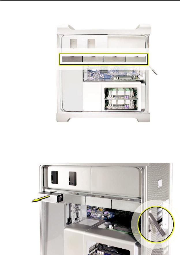
Part Location
Procedure
1.Make sure the latch on the back panel is up, so that the drives and carriers are unlocked.
2.Pull the hard drive out of the drive bay.
Mac Pro (Early 2008) Take Apart — Hard Drives 17
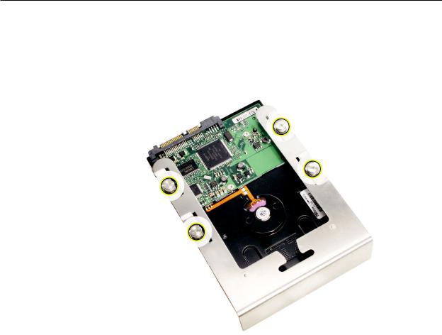
3.If you are replacing the hard drive with a new drive, remove the four screws that mount the drive to the carrier and mount the new drive in the carrier.
Important: Hold the drive by its sides. Be careful not to touch the printed circuit board on the bottom of the drive.
Replacement Note: Slide the carrier and drive over the guides and into the drive bay, until you feel the drive snap into place.
Note: If you install a new (replacement) drive, format it by following these steps:
1.Open Disk Utility and select the drive in the list to the left.
Note: If you are formatting the primary drive, use the Disk Utility program on the Install Disk.
2.Click on the Partition tab.
3.Click on “Options” and verify GUID is selected if this is a bootable drive.
4.Apply the change by clicking on the “Partition” button.
Mac Pro (Early 2008) Take Apart — Hard Drives 18
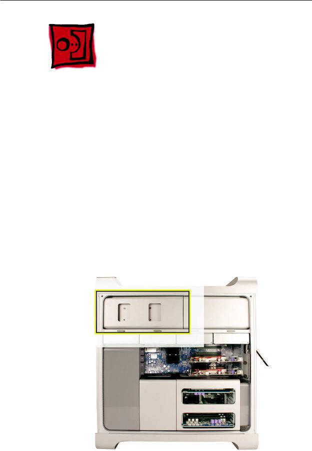
Optical Drive Carrier and
Optical Drives
The Mac Pro (Early 2008) computer can accommodate two optical drives in the optical drive bay. If the computer has only one optical drive, it is installed in the top position.
Note: To eject the drives, use the following:
•Top drive: Press the Eject key.
•Bottom drive:Press the Option and Eject keys.
Tools
The only tool required for this procedure is a Phillips #1 screwdriver.
Preliminary Steps
Before you begin, open the computer, and lay it on its side with the access side facing up.
Important: Make sure the latch on the back panel is in the up position. When the latch is down, the optical drives and carrier are locked in place and you will not be able to remove them.
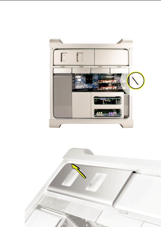
Part Location
Mac Pro (Early 2008) Take Apart — Optical Drive Carrier and Optical Drives 19
Procedure
Removing the Optical Drive Carrier and Optical Drives
1.Make sure the latch on the back panel is up, so that the drives and carriers are unlocked.
2.Pull the optical drive carrier part way out of the computer.
Mac Pro (Early 2008) Take Apart — Optical Drive Carrier and Optical Drives 20
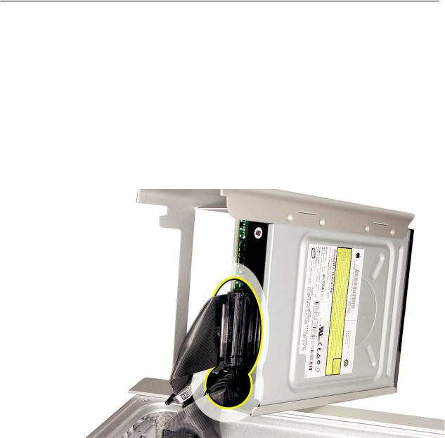
3.Disconnect the power and ribbon cables from the optical drive(s) and remove the carrier.
4.If you are replacing the optical drive with a new optical drive, do the following:
•Remove the four mounting screws and remove the optical drive from the carrier.
•Use the four screws to mount the replacement drive in the carrier.
Note: If you are adding a second drive to the carrier, use the four screws stored on the back of the drive carrier to secure the drive to the carrier.
Mac Pro (Early 2008) Take Apart — Optical Drive Carrier and Optical Drives 21
Replacing the Optical Drive Carrier and Optical Drives
Important: Use the original Apple cables that came with the computer when you install or replace the optical drives. If just one optical drive is installed, tuck the cables for the second drive out of the way.
1.Attach the power and ribbon cables to the back of the drive(s).
Important: Attach the connector on the end of the optical drive ribbon cable and the connector in the middle of the optical drive power cable to the top drive. If there is a second drive in the carrier, attach the remaining optical drive ribbon and power connectors to the bottom drive.
2.Slide the optical drive carrier over the guides and into place in the optical drive bay.
Important: Be very careful not to catch the cables under the carrier as you slide it into the bay.
Mac Pro (Early 2008) Take Apart — Optical Drive Carrier and Optical Drives 22
Memory (FB-DIMMs) and
Memory Riser Cards
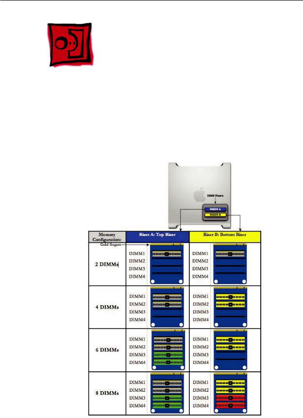
The Mac Pro (Early 2008) computer has two memory riser cards with a total of 8 memory slots. On each card, the slots are arranged as two banks of two slots each. The computer comes with a minimum of 2 GB of memory, installed as a pair of 1 GB fully buffered, dual inline memory modules (FB-DIMMs) in two of the DIMM slots. Additional pairs of 1 GB, 2 GB, or 4 GB FB-DIMMs can be installed in the open DIMM slots, as illustrated below. Maximum memory is 32 GB.
DIMMs must be installed as pairs of identical size and type, from the same vendor. In the illustration below, like-colored DIMMs must match.
Mac Pro (Early 2008) Take Apart — Memory (DIMMs) and Memory Riser Cards 23
DIMMs for Mac Pro (Early 2008) must fit these specifications:
•800 MHz, DDR2, FB-DIMMs
•72-bit wide, 240-pin modules
•36 memory ICs maximum per DIMM
•Error-correcting code (ECC)
Memory from older Macintosh computers is not compatible with Mac Pro (Early 2008).
Important: For proper operation of Mac Pro (Early 2008) computers, Apple recommends using only Apple-approved Mac Pro (Early 2008) FB-DIMMs. Refer to GSX for Apple FB-DIMMs service part numbers.
Tools
No tools are required for this procedure.
Preliminary Steps
Before you begin, open the computer, and lay it on its side with the access side facing up.
Warning: Always wait 5–10 minutes for the computer to cool down before you remove or install memory. The DIMMs may be very hot.
Part Location
Mac Pro (Early 2008) Take Apart — Memory (DIMMs) and Memory Riser Cards 24
Procedure
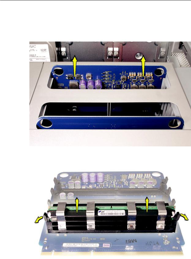
1.Holding the memory riser card by the two finger holes, pull it out of the memory cage and place the card DIMM side up on a soft, clean cloth.
2.Open the ejectors on the DIMM slot by pushing them out to the sides, and remove the DIMM from the riser card.
Mac Pro (Early 2008) Take Apart — Memory (DIMMs) and Memory Riser Cards 25
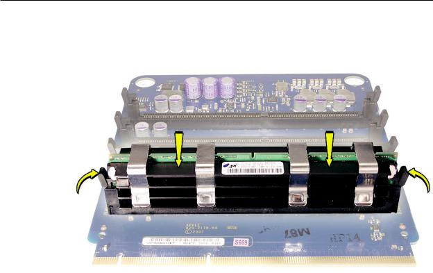
Replacement Note: Align the DIMM in the slot on the riser card and push both ends of the DIMM down until the ejectors snap back up into place.
Warning: FB-DIMMs carry heatsinks on either side of the DIMM. Never attempt to remove the heatsinks from the DIMMs. Doing so could damage the DIMM.
Mac Pro (Early 2008) Take Apart — Memory (DIMMs) and Memory Riser Cards 26
 PCI Express/Graphics Card
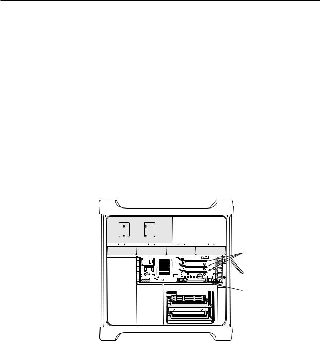
The Mac Pro (Early 2008) logic board includes one double-wide PCI Express graphics slot and three PCI Express expansion slots, for a total of four slots. The computer comes with a graphics card installed in slot 1. You can install additional PCI Express graphics and expansion cards in the remaining three PCI Express expansion slots.
Important: Graphics cards from previous Power Mac G5 models are not compatible with Mac Pro (Early 2008) models. In addition, Mac Pro (Early 2008) graphics cards are not compatible with previous models.
Important: Combined maximum power consumption for all four PCI Express slots must not exceed 300 W.
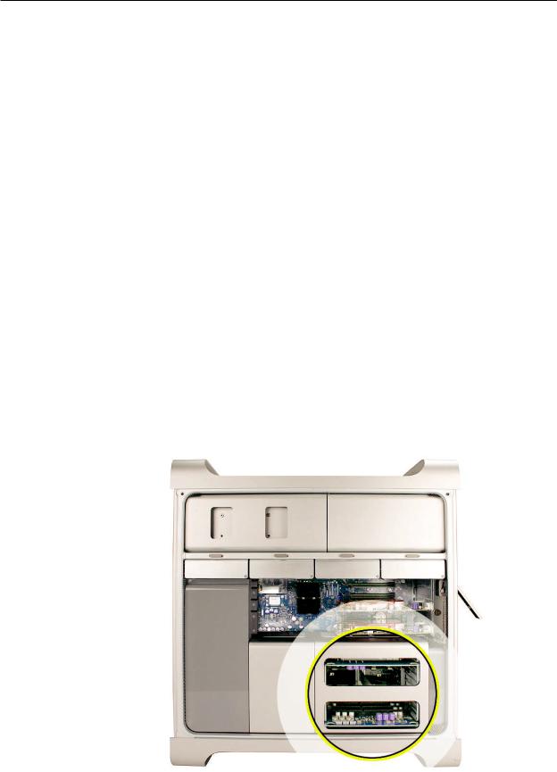
Slots 2–4: PCI Express
Slot 1: Double-wide PCI Express graphics
(graphics card installed)
Tools
The only tool required for this procedure is a Phillips #1 screwdriver.
Preliminary Steps
Before you begin, open the computer, and lay it on its side with the access side facing up.
Note: You may also find it helpful to remove the hard drives and carriers and any adjacent PCI Express cards before beginning this procedure.
Mac Pro (Early 2008) Take Apart — PCI Express/Graphics Card 27

Part Location
Procedure
This procedure explains how to remove a standard card and a card that includes a booster cable.
Before you can remove either type of card, however, you must first loosen the two captive screws that secure the PCI bracket to the enclosure and remove the bracket.
Mac Pro (Early 2008) Take Apart — PCI Express/Graphics Card 28
Warning: When removing or installing a card, handle it only by the edges. Do not touch its connectors or any of the components on the card. Lift the card straight out from the connector to remove it, and insert it straight into the connector to install it. Do not rock the card from side to side and don’t force the card into the slot. Once the replacement card is installed, pull on it gently to check that it is properly connected.
Standard Card
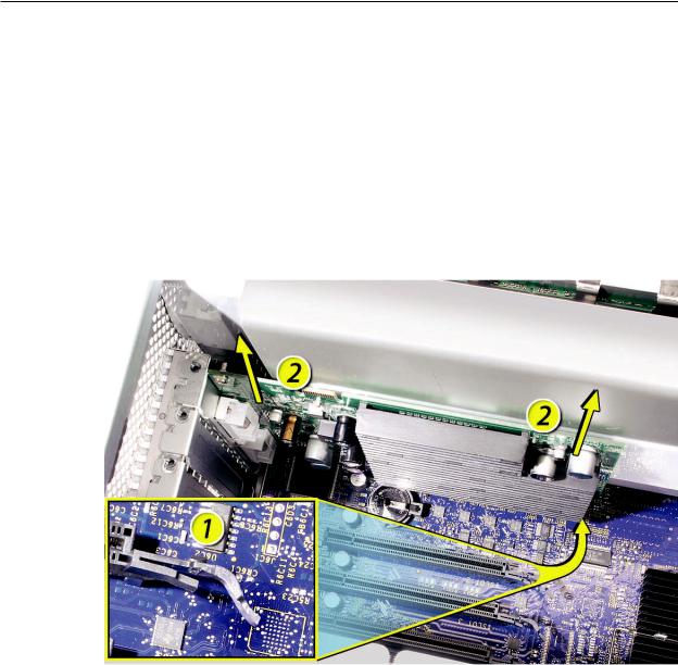
1.Release the small locking clip at the front of the card’s logic board connector by pushing the clip up toward the media shelf.
2.Holding the card by the top corners, pull up the card and remove it from its expansion slot.
Replacement Note: Align the card’s connector with the expansion slot and press until the connector is inserted all the way into the slot. If you’re installing a 12-inch card, make sure the card engages the appropriate slot in the PCI card guide.
•Don’t rock the card from side to side; instead, press the card straight into the slot.
•Don’t force the card. If you meet a lot of resistance, pull the card out. Check the connector and the slot for damage or obstructions, then try inserting the card again.
•Pull the card gently to see if it is properly connected. If it resists and stays in place and its gold connectors are barely visible, the card is connected.
Mac Pro (Early 2008) Take Apart — PCI Express/Graphics Card 29
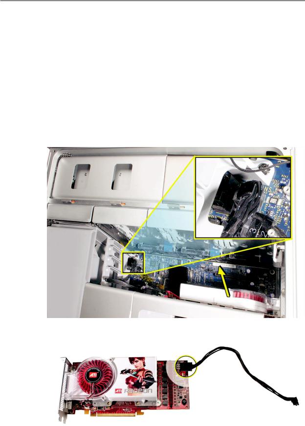
Card with Booster Cable
Some graphics cards require either one or two booster cables connecting the card to the auxillary power connectors on the logic board.
Note: The graphics card NVIDIA GeForce 8800 GT requires one booster cable; the graphics card
NVIDIA Quadro FX 5600 requires two booster cables.
1.Disconnect the booster cable(s) from the logic board.
2.Release the small locking clip at the front of the card’s logic board connector by pushing the clip up toward the media shelf.
3.Holding the card by the top corners, gently pull up the card and remove it from its expansion slot.
4.If you are replacing a booster cable with a new one, disconnect the cable from the card.
Mac Pro (Early 2008) Take Apart — PCI Express/Graphics Card 30
Loading...