


 Loading...
Logic Pro 7.2.1
Dedicated Control
Surface Support
Apple Computer, Inc. © 2004–2006 Apple Computer, Inc. All rights reserved.
Under the copyright laws, this manual may not be copied, in whole or in part, without the written consent of Apple. Your rights to the software are governed by the accompanying software licence agreement.
The Apple logo is a trademark of Apple Computer, Inc., registered in the U.S. and other countries. Use of the “keyboard” Apple logo (Option-Shift-K) for commercial purposes without the prior written consent of Apple may constitute trademark infringement and unfair competition in violation of federal and state laws.
Every effort has been made to ensure that the information in this manual is accurate. Apple Computer, Inc. is not responsible for printing or clerical errors.
Apple Computer, Inc. 1 Infinite Loop Cupertino, CA 95014-2084 408-996-1010 www.apple.com
Apple, the Apple logo, Aqua, Final Cut, Final Cut Pro, FireWire, iBook, iMac, iPod, iTunes, Logic, Mac, Macintosh, Mac OS, PowerBook, Power Mac, Power Macintosh, and QuickTime are trademarks of Apple Computer, Inc., registered in the U.S. and other countries.
Finder and GarageBand are trademarks of Apple
Computer, Inc.
AppleCare is a service mark of Apple Computer, Inc.
Other company and product names mentioned herein are trademarks of their respective companies. Mention of third-party products is for informational purposes only and constitutes neither an endorsement nor a recommendation. Apple assumes no responsibility with regard to the performance or use of these products.

1 Contents
Preface |
7 |
Introduction |
|
7 |
What Are Control Surfaces? |
|
8 |
How Control Surface Integration Works |
Chapter 1 13 Control Surface Setup
13 Control Surface Plug-ins
13About Software and Firmware
14Getting Started
15Connecting the Unit(s)
16Installing and Setting Up Control Surfaces
17Control Surface Groups
19 Setup Window Parameters
25 Control Surface Preferences
29 Customizing Control Surfaces
34 The Controller Assignments Editor
45About Modal Dialogs
46Tips
Chapter 2 47 Logic Control
47Set Up
48The Displays
50 The Channel Strip(s)
54 The Assignment Zone
69 Fader Bank Zone
71 Master Fader
71 Display Zone
73The Function Key Zone
74The Global View Zone
75Function Button Zone
79The Transport Zone
87The Cursor/Zoom Key Zone
88The Jog/Scrub Wheel Zone
89Assignment Overview
|
3 |
|
|
Chapter 3 101 M-Audio iControl
101Setting Up the iControl
102Compatibility
102 Channel Views
102 The Assignment Buttons
105Arrow Up and Arrow Down Buttons
105The Channel Strip(s)
106The Jog Wheel
106The Transport Zone
107Master Fader
108Assignment Overview
Chapter 4 |
111 |
EuCon Support of Euphonix MC and System 5-MC |
|
111 |
Setting Up the MC or System 5-MC With Logic |
|
112 |
Setting Up Soft Key Assignments |
|
113 |
Main-Tracks Touchscreen |
|
113 |
Main-Layouts |
|
113 |
Faders |
|
114 |
Choosing Automation Modes |
|
115 |
Knobsets |
|
120 |
Monitors and Control Room |
|
120 |
Clear Keys |
|
120 |
Track Control Bar |
|
120 |
System 5-MC Specific Features |
Chapter 5 |
123 |
CM Labs Motormix |
|
123 |
Set Up |
|
123 |
Assignment Overview |
Chapter 6 |
131 |
Frontier Design TranzPort |
|
131 |
Set Up |
|
131 |
LCD |
|
132 |
Assignment Overview |
Chapter 7 |
135 |
JLCooper CS-32 MiniDesk |
|
135 |
Set Up |
|
135 |
Assignment Overview |
Chapter 8 |
141 |
JLCooper FaderMaster 4/100 |
|
141 |
Requirements |
|
141 |
Set Up |
|
142 |
Assignment Overview |
4 |
Contents |
|
|
Chapter 9 |
143 |
Korg microKONTROL and KONTROL49 |
|
143 |
Set Up |
|
143 |
Assignment Overview |
Chapter 10 |
147 |
Mackie Baby HUI |
|
147 |
Set Up |
|
147 |
Assignment Overview |
Chapter 11 |
151 |
Mackie C4 |
|
151 |
Set Up |
|
151 |
V-Pots, V-Selects |
|
157 |
Buttons at Bottom |
|
160 |
Marker Overlay |
|
160 |
Track Overlay |
|
160 |
Channel Strip Overlay |
|
161 |
Function Overlay |
Chapter 12 |
163 |
Mackie HUI |
|
163 |
Set Up |
|
163 |
Assignment Overview |
Chapter 13 |
173 |
Radikal Technologies SAC-2K |
|
173 |
Set Up |
|
173 |
Assignment Overview |
|
178 |
Troubleshooting |
Chapter 14 |
179 |
Roland SI-24 |
|
179 |
Set Up |
|
179 |
Assignment Overview |
Chapter 15 |
185 |
Tascam FW-1884 |
|
185 |
Introduction |
|
185 |
Set Up |
|
185 |
Assignment Overview |
Chapter 16 |
193 |
Tascam US-2400 |
|
193 |
Set Up |
|
194 |
Assignment Overview |
Chapter 17 |
199 |
Tascam US-428 and US-224 |
|
199 |
Set Up |
|
199 |
Assignment Overview |
Chapter 18 |
203 |
Yamaha 01V96 |
|
203 |
Set Up |
Contents |
5 |
|
|
204 Assignment Overview
206Selected Channel Section
207Data Entry Section
207 Channel Strips
207Stereo Channel Strip
208User Defined Keys Section
Chapter 19 211 Yamaha 02R96
211Set Up
212Assignment Overview
Chapter 20 217 Yamaha DM1000
217Set Up
218Assignment Overview
Chapter 21 225 Yamaha DM2000
225Set Up
226Assignment Overview
Appendix A 235 Logic Control—Specifications
235 Logic Control (Base Unit)
237 Logic Control XT (Extension Unit)
Appendix B 239 Logic Control—MIDI Implementation
239SysEx Message Header
240Global Control Messages
242Common Control Messages
Appendix C 251 Logic Control—Control Surface Layout and IDs
Appendix D 255 Logic Control—MIDI Implementation Chart
6 |
Contents |
|
|

Introduction
This manual covers the control surface support of Logic Pro. Please read it thoroughly to make the most of your new controller(s).
All of the functions in Logic Pro that are normally associated with the use of an analog style mixer can be performed using just a mouse and a computer keyboard. The addition of many commercially available control surfaces can greatly enhance your creative experience by providing you with hands-on control of most realtime parameters in Logic. Move a fader and the on-screen fader in Logic will move with it. Similarly, when you make a fader move on-screen, the control surface fader moves (this only applies to control surfaces equipped with motorized faders). Adjust EQ parameters by turning one of your control surface’s knobs and Logic will update instantly.
What Are Control Surfaces?
Control surfaces are hardware units that enable the operation of Logic Pro using faders, rotary knobs, switches, and displays.
There are a number of simple control surfaces that feature conventional faders and no displays. More progressive units are equipped with motorized faders, rotary encoders, LED rings, and programmable displays. The more feedback a control surface provides, the easier it is to use, as you don’t need to watch the computer screen in order to determine what mode the unit is currently in.
Control surfaces—dependent on the options (buttons, knobs, switches, displays, and so on) available—have the potential to:
Âcontrol all Logic transport functions
Âadjust instrument, input, bus, aux, master, and audio channel volume and pan levels
Âcontrol Channel EQ and Linear Phase EQ parameters
Âselect and control all effect and Instrument parameters
Âselect, solo, mute, and arm tracks
Âset and adjust send parameters
|
7 |
|
|
Âremotely switch between Screensets
Âscrub MIDI and audio
Âzoom in on individual tracks
Âcreate, delete, and move between markers, and much more
For live use, control surfaces are ideal. The performing musician only needs to take a laptop, equipped with suitable audio and/or MIDI interfaces, a keyboard, and a control surface to a live event. Some units available nowadays incorporate a keyboard, audio interface, control surface, and MIDI interface into a single package.
Given that Logic Pro’s track automation facilities can be active, even when not in record mode, you can capture your “live” real time changes for later recall. This ensures that you’ll never again lose that “once-in-a-lifetime” performance—on stage or in the studio.
How Control Surface Integration Works
Logic Pro features dedicated support for a number of control surface models. This is achieved through several plug-ins that are directly integrated into Logic. Some plug-ins support multiple, similarly-featured control surface models.
Note: Although many other control surfaces are supported, the Logic/Mackie Control,
C4, and XT control surface units are recommended for use with Logic.
Logic also allows you to reprogram existing assignments for supported control surfaces and to program new assignments for unsupported control surfaces. This facility allows you to extend the use of faders, knobs, and switches, either directly or through the use of modifier commands.
You can use any combination of control surfaces with Logic Pro. You will get most out of them, however, when used in a Control Surface Group (provided all devices are supported by the same plug-in).
Universal information, that applies to all control surfaces, is covered in the following chapter. Please read this before taking a look at the dedicated section on your control surface(s).
A detailed overview of group, installation, and other control surface setup parameters is found in Chapter 1,“Control Surface Setup,” on page 13. Please read this, as it contains a lot of useful information that will help you to customize and/or make the most of your control surface(s).
Important: Specific information on device setup is found at the beginning of the relevant chapter for your control surface (see the table below).
8 |
Chapter Introduction |
|
|
It is assumed that you are familiar with the basic use and terminology of Logic Pro. As such, the functionality and uses of individual Logic parameters are not covered in this documentation. Please consult your Logic Pro 7 Reference manual or the Online Help, if you require further information.
You are strongly encouraged to press buttons, move sliders and turn the knobs of your control surface while reading through the following chapters. This will help you to get a “feel” for how your control surface works, and how the various parts of the control surface interact with one another, and Logic.
A listing of control surfaces that are directly supported by Logic (via a control surface plug-in included in the Logic package), how they differ from similar devices, and cross references to the relevant sections are shown below.
Note: It is possible that your device may be directly supported in Logic via a suitable control surface plug-in, supplied by the manufacturer. Please check the website of your control surface manufacturer. Follow any written instructions supplied with the plug-in, if available.
Supported Devices |
Manufacturer |
Notes |
01V96 |
Yamaha |
The Yamaha 01V96 emulates two HUI units, using |
|
|
two virtual MIDI in and out connections over its |
|
|
USB cable. |
|
|
See “Yamaha 01V96” on page 203. |
|
|
|
01X |
Yamaha |
The Yamaha 01X emulates a Logic Control. It does |
|
|
not feature all controls available to the Logic (and |
|
|
Mackie) units, however. Please refer to the 01X |
|
|
documentation for details. |
|
|
Logic recognizes the 01X as such and displays a |
|
|
custom icon, but communication is as with a |
|
|
Logic Control. |
|
|
See “Logic Control” on page 47. |
|
|
|
02R96 |
Yamaha |
The Yamaha 02R96 emulates three HUI units, |
|
|
using three virtual MIDI in and out connections |
|
|
over its USB cable. |
|
|
See “Yamaha 02R96” on page 211. |
|
|
|
Baby HUI |
Mackie |
The Baby HUI is a stripped-down version of the |
|
|
HUI. See “Mackie Baby HUI” on page 147. |
|
|
|
C4 |
Mackie |
The Logic Control plug-in has been extended to |
|
|
support the Mackie C4. |
|
|
See “Mackie C4” on page 151. |
|
|
|
CM408T |
Euphonix |
See “EuCon Support of Euphonix MC and System |
|
|
5-MC” on page 111. |
|
|
|
CS-32 MiniDesk |
JLCooper |
See “JLCooper CS-32 MiniDesk” on page 135. |
|
|
|
Chapter Introduction |
9 |
|
|
Supported Devices |
Manufacturer |
Notes |
DM1000 |
Yamaha |
The Yamaha DM1000 emulates two HUI units, |
|
|
using two virtual MIDI in and out connections |
|
|
over its USB cable. |
|
|
See “Yamaha DM1000” on page 217. |
|
|
|
DM2000 |
Yamaha |
The Yamaha DM2000 emulates three HUI units, |
|
|
using three virtual MIDI in and out connections |
|
|
over its USB cable. |
|
|
See “Yamaha DM2000” on page 225. |
|
|
|
FaderMaster 4/100 |
JLCooper |
See “JLCooper FaderMaster 4/100” on page 141. |
|
|
|
FE-8 |
Tascam |
Extension unit for FW-1884. See “Tascam FW- |
|
|
1884” on page 185. |
|
|
|
FW-1082 |
Tascam |
A stripped-down version of the FW-1884, with |
|
|
dedicated support in the FW-1884 plug-in. |
|
|
See “Tascam FW-1884” on page 185. |
|
|
|
FW-1884 |
Tascam |
See “Tascam FW-1884” on page 185. |
|
|
|
HUI |
Mackie |
Important: The HUI plug-in has been tested with |
|
|
the original Mackie HUI. There are a number of |
|
|
control surfaces not mentioned here which can |
|
|
emulate the HUI. We have not tested all devices |
|
|
capable of HUI emulation, and don’t provide any |
|
|
support for them, nor do we guarantee that they |
|
|
will work with Logic in HUI emulation mode. |
|
|
See “Mackie HUI” on page 163. |
|
|
|
iControl |
M-Audio |
See “M-Audio iControl” on page 101. |
|
|
|
KONTROL 49 |
Korg |
A larger version of the microKONTROL, with |
|
|
dedicated support in the microKONTROL plug-in. |
|
|
See “Korg microKONTROL and KONTROL49” on |
|
|
page 143. |
|
|
|
Logic Control XT |
Mackie/Emagic |
This is the extension unit for the Logic Control. It |
|
|
only offers the channel strip section, making it |
|
|
less useful without a Logic Control. See “Logic |
|
|
Control” on page 47. |
|
|
Also see the Appendix for more details. |
|
|
|
Logic/Mackie Control |
Mackie/Emagic |
See “Logic Control” on page 47. |
|
|
Also see the Appendix for more details. |
|
|
|
Mackie Control |
Mackie |
The original Mackie Control hardware is similar to |
|
|
the Logic Control. The front panel legend is |
|
|
different, however. You should request a Logic |
|
|
Control Lexan Overlay from Mackie. As Logic also |
|
|
recognizes the Mackie Control protocol, you may |
|
|
use any firmware version. If you have firmware |
|
|
version 1.02 or higher, you can freely use either |
|
|
the Logic Control or Mackie Control mode. |
|
|
See “Logic Control” on page 47. |
|
|
|
10 |
Chapter Introduction |
|
|
Supported Devices |
Manufacturer |
Notes |
Mackie Control Extender |
Mackie |
Mackie Control version of the Logic Control XT. As |
|
|
Logic also recognizes the Mackie Control |
|
|
protocol, you may use any firmware version. If |
|
|
you have firmware version 1.02 or higher, you can |
|
|
freely use either the Logic Control or Mackie |
|
|
Control mode. |
|
|
See “Logic Control” on page 47. |
|
|
|
Mackie Control Universal |
Mackie |
A Mackie Control with Logic Control silk |
|
|
screening (legend) and firmware version 2.0 or |
|
|
higher (including HUI emulation). As Logic also |
|
|
recognizes the Mackie Control protocol, you may |
|
|
use any firmware version. If you have firmware |
|
|
version 1.02 or higher, you can freely use either |
|
|
the Logic Control or Mackie Control mode. |
|
|
See “Logic Control” on page 47. |
|
|
|
MC |
Euphonix |
See “EuCon Support of Euphonix MC and System |
|
|
5-MC” on page 111. |
|
|
|
microKONTROL |
Korg |
See “Korg microKONTROL and KONTROL49” on |
|
|
page 143. |
|
|
|
Motormix |
CM Labs |
See “CM Labs Motormix” on page 123. |
|
|
|
Radikal Technologies |
SAC-2.2 |
There is a dedicated plug-in for the SAC-2.2/2k’s |
|
|
native mode. |
|
|
The Logic Control plug-in detects an SAC-2.2 (in |
|
|
Logic Control emulation mode) and ignores it, |
|
|
avoid two installations of the SAC-2.2. |
|
|
See “Radikal Technologies SAC-2K” on page 173. |
|
|
|
Radikal Technologies |
SAC-2k |
See “Radikal Technologies SAC-2K” on page 173. |
|
|
|
SI-24 |
Roland |
See “Roland SI-24” on page 179. |
|
|
|
TranzPort |
Frontier Design Group See “Frontier Design TranzPort” on page 131. |
|
|
|
|
US-224 |
Tascam |
A stripped-down version of the US-428, with |
|
|
dedicated support in the US-428 plug-in. |
|
|
See “Tascam US-428 and US-224” on page 199. |
|
|
|
US-2400 |
Tascam |
Logic has support for the US-2400’s native mode. |
|
|
In contrast to its Logic Control mode, all controls, |
|
|
including the joystick, are supported. |
|
|
See section “Tascam US-2400” on page 193. |
|
|
|
US-428 |
Tascam |
See “Tascam US-428 and US-224” on page 199. |
|
|
|
Chapter Introduction |
11 |
|
|

1 |
Control Surface Setup |
1 |
|
||
|
|
|
Logic offers dedicated support for a number of control surfaces, plus the option to program unsupported devices.
The following chapter describes functions applicable to all control surface models.
Specific documentation for various models is available in the following chapters.
Control Surface Plug-ins
Dedicated control surface support is achieved through the use of special plug-in files.
These files are automatically added when Logic is installed.
They are located in the /Contents/MIDI Device Plug-ins sub-folder of the Logic application bundle (to view the bundle contents, Control or right-click on the Logic application icon, and choose Show Package Contents from the menu). Logic also checks for control surface plug-ins in the (optional) “/Library/Application Support/ Logic/MIDI Device Plug-ins” and “~/Library/Application Support/Logic/MIDI Device Plug-ins” (the “~” denotes your user home directory) folders.
When new control surface plug-ins are released independently from a Logic update, please place them in the folders described above (or as advised in the documentation supplied with the plug-in).
About Software and Firmware
Most control surfaces have no “intelligence” of their own. Their functionality is host software-based, making them reliant on Logic to tell them what to do/how to behave. What this means is that control surfaces cannot perform any function that Logic itself isn’t capable of. It also means that if Logic is not booted, most control surface units will do nothing at all.
This reliance on the host application makes your control surface the ultimate upgradable hardware. As new functions are added to Logic, or you create new assignments (see “Control Surface Setup” on page 13), your control surface will be able to access and control them.
|
13 |
|
|
Most control surface units do, however, have a form of software called “firmware.”This firmware is much like the BIOS found in your computer. New behaviors—at a hardware level—such as improved control of fader servo motors and changes to the display can be made via firmware updates.
The firmware is usually stored on an EEPROM (Electronically Erasable Programmable Read Only Memory) chip. It can often be updated via a simple MIDI dump procedure, in the form of a MIDI file.
Should new firmware become available, you can simply download the appropriate MIDI file and play it to your control surface(s), which will be updated accordingly. The steps required to perform a firmware update will be outlined in the documentation that accompanies the MIDI file. Please read this before attempting any update.
Note: Some control surfaces may require a physical chip replacement for firmware updates. Please contact the manufacturer of your device for details.
Getting Started
To make use of your control surface, you will require:
ÂAn installed, authorized copy of Logic Pro.
ÂIf a USB or FireWire equipped device (such as a Yamaha 01X)—a free USB or FireWire port. This should preferably be a direct USB/FireWire connection with the computer, rather than via a USB/FireWire hub. Please refer to the documentation provided by the manufacturer of your control surface.
ÂIf a MIDI-only device (such as a Logic Control)—a free MIDI in and out port for each unit, on any suitable MIDI interface. As an example; if using a Unitor 8 or AMT 8, which feature 8 MIDI in and 8 MIDI out ports, with one Logic Control and one Logic Control XT, you will need to use two of the Unitor8/AMT8’s MIDI ins and two of its MIDI outs.
ÂAn installed driver (if required by your control surface) that is supported by the operating system version being used.
Important: Your MIDI interface must feature driver software that supports SysEx communication. Please consult the documentation that shipped with your MIDI interface.
The number of units that can be run simultaneously is dependent on the availability of free MIDI in and out, FireWire or USB ports on your system. In a standard setup, a single control surface will be used alone, or accompanied by one or more units. It is also possible to make use of several units to create Control Surface Groups, as discussed in “Control Surface Groups” on page 17.
14 |
Chapter 1 Control Surface Setup |
|
|
The use of multiple control surfaces expands on the number of tracks, parameters, and so on that can be controlled with individual faders, knobs, and switches. As an example, the Logic/Mackie Control XT units are basically identical to the channel strip section (fader, V-Pot, and LCD) of the main Logic/Mackie Control unit. The Mackie C4 features a number of V-Pots, but no faders. You may add as many XT, C4, or other control surface units as you wish to your Logic system, provided enough MIDI in and out ports are available.
Connecting the Unit(s)
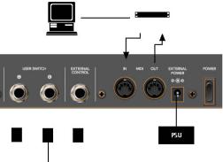
Connect your (MIDI) control surfaces as shown in the diagram below.
Computer |
|
MIDI Interface |
|
||
|
|
|
|
|
|
Optional Footswitches
As mentioned earlier, each MIDI control surface must have a discrete MIDI in and MIDI out connection. Do not “daisy-chain” other MIDI devices via MIDI thru to the MIDI in or out ports used by control surfaces, as this may result in data errors.
FireWire and USB units are connected via a single cable to the computer. It is generally recommended that this is a direct connection with the Macintosh, rather than via a FireWire/USB hub. Daisy-chaining or the use of hubs can result in data errors.
Optional Footswitches and Pedals
If your control surface features suitable connectors, you may use optional foot switches to remotely control start/stop and other functions. This may be useful when using guitars or other instruments that require two-handed playing.
Chapter 1 Control Surface Setup |
15 |
|
|
Power Up
Once everything is connected, press the power switch on your control surface. Once powered, the displays and/or LEDs will illuminate and the LCD (if applicable) will generally display a welcome message (often including the firmware version number). Each fader will slide to the top, and back to the bottom of its travel on most motorized control surfaces. This self-diagnostic power-on procedure indicates that your units are functioning correctly.
Your computer and MIDI interface can be powered up before or after initialization of your control surface units. Logic can be started either before or after the units have completed initialization.
Installing and Setting Up Control Surfaces
Some control surface units (Logic/Mackie Control, for example) will automatically be detected when Logic is launched. Units which are not detected automatically can be added via the Setup window. This is accessed via the Setup option in the Preferences > Control Surfaces menu.
Installation is very easy (and is covered in the Set Up section of the chapter on your specific device). Some devices may require different or additional steps, but generally, all you need to do is select the device(s) that you wish to use in Logic, as follows:
To install control surfaces using the Scan function of Logic:
1Choose New > Install, and in the ensuing Install window, select the desired device from the list.
Note: You may select one or more models. To select more than one model, select them with Command held down. If you select more than one model, Logic performs the desired operation for each model in turn.
2Press the Scan button. You can also press Enter or double-click the device name.
Logic will then analyze your MIDI system, and will automatically install the devices it finds, including the correct connection settings.
Note: The Scan function is preferable to manual installation, as Logic is able to gather the maximum amount of information about the devices.
If you don’t want to select the models to be scanned manually, you can also click “Scan all.”This will search for all supported control surface units on all MIDI ports. Please be aware that this may take a while.
Some control surfaces don’t support automatic scanning. Such devices must be added manually to your setup. In this scenario, you will need to manually set the MIDI In and Out port parameters.
16 |
Chapter 1 Control Surface Setup |
|
|
To manually add the selected devices to your system:
1Select the desired devices from the list in the Install window.
2Click the Add button.
Note: Alternatively you can Option-double-click the desired device.
If a control surface of the selected type already exists in your setup, you will be asked whether or not you really want to add the new device. You will need to manually alter the MIDI In and Out port values in the device parameters to match those of the connected unit.
Once you have completed the scanning or installation of the devices, click Done. The Install window will close.
Rebuilding Defaults
The Preferences > Control Surfaces > Rebuild Defaults option re-initializes the support of all connected control surfaces.
Control Surface Groups
If you have multiple control surface units, you can define how they relate to each other, and build Control Surface Groups. A Control Surface Group consists of a number of control surface units (using the same plug-in) which are combined to create a single, unified (and larger) control surface.
You can build up to 20 Control Surface Groups. Each “group” can consist of any number of physical units. The only limiting factor is the number of available MIDI In/Out (or USB/FireWire—defined as MIDI) ports.
When multiple control surface units are combined, you can independently determine the default behavior for each physical device. This is discussed in the Device Parameters (p. 19) section.
To build a Control Surface Group out of several units:
mSimply arrange their icons (in the Setup window) in a single horizontal row—by dragging each icon to the desired onscreen location.
The order of the icons from left to right also defines how the tracks and parameters are arranged on the units.
To use two control surfaces independently:
mSimply arrange them in separate rows—that is, one above the other.
Chapter 1 Control Surface Setup |
17 |
|
|
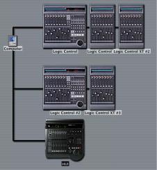
Here is an example with two Logic Control, three Logic Control XT units and a HUI:
Computer icon connected to three rows, as below:
The top row, consisting of Logic Control XT #1, Logic Control XT #2 and Logic Control #1 form a single Control Surface Group with 24 channels. XT #1 controls channels 1 to 8, XT #2 controls channels 9 to 16, and Logic Control #1 handles channels 17 to 24.
Logic Control #2 and Logic Control XT #3 form a second Control Surface Group, displaying, say instruments (on channels 1 to 8) and busses (on channels 9 to 16).
The HUI forms a single unit control surface group.
Each Control Surface Group has individual settings, such as Flip Mode, Fader Bank Offset, Plug-in Parameter Bank Offset and others. This allows you to access, edit, and automate different sections of the Logic mixer.
In our example, the three units in the top row could be used for control over audio tracks and MIDI channels. In the middle row, Logic Control #2 could be used for Audio Instrument channels 1 to 8, and XT #3 could be used for busses. The HUI might edit group definitions. The physical placement of units, and the way you use them, is entirely up to you.
Note: The placement of your control surface units in relation to each other should be the same onscreen as in the real-world. Simply drag ’n drop the desired icon horizontally in your Control Surface Group to do so.
18 |
Chapter 1 Control Surface Setup |
|
|
Setup Window Parameters
The three Parameter boxes along the left edge of the Setup window allow you to configure your control surface setup to meet your needs.
Device Parameters
Each control surface unit must be connected to an independent MIDI in and out port (or corresponding USB/FireWire port, designated as a MIDI port by the device driver). The automatic setup or Scan procedure should have found, and set, the correct MIDI in/ out port settings for each unit.
In the event that the MIDI in or out port identification is incorrect, you can manually select the appropriate one for the unit. To do so, click-hold on the MIDI Input and Output pull-down menus, and select the appropriate port(s) of your MIDI interface/ device.
Some devices allow you to define a device ID (or global/basic channel). This can be set in this area. Module name, model name and firmware version are also displayed in the device parameters.
The Color parameter defines the color of the Track Control Bar—a bar displayed in the Arrange window, indicating the tracks that are currently being accessed by your control surface. The Track Control Bar of each control surface can be assigned a different color.
Special Parameters
Some control surfaces may allow the definition of “special” parameters. An example of this is fader touch sensitivity. Such parameters can be found in the Special Parameters area. A detailed description can be found in the documentation of the particular control surface plug-in.
Control Surface Group Parameters
The following parameters are shown in the Setup window. They apply to the Control Surface Group associated with the selected device, and allow you to set each group up to meet your needs. This facility is of great benefit when multiple Control Surface Groups have been created.
Many (if not all) Control Surface Group parameters can also be changed directly from the control surface. The parameter display in the Setup window is for information purposes only.
Any changes to settings (made here, or on the control surface) are saved in a preferences file, which is independent of the Logic program preferences: it’s named “com.apple.logic.pro.cs”, and is located in ~/Library/Preferences/Logic.
Chapter 1 Control Surface Setup |
19 |
|
|
Display Parameters
The following section describes the display parameters of a Control Surface Group.
Flip Mode
Many control surfaces offer both a fader and a rotary encoder for each channel strip. Flip Mode allows you to swap the encoder assignment with that of the fader for each channel. Alternately, you can assign both controls to the same parameter.
There are four “flip” or “swap” modes.
ÂOff—disables Flip Mode, making the fader act as a volume control.
ÂDuplicate—makes both the fader and encoder active for the currently selected encoder parameter.
ÂSwap—swaps the fader and encoder, making the fader a pan control and the encoder a channel volume control, for example.
ÂMute—disables the faders. This is useful for situations where recording is taking place in the same room as the control surface, and you wish to avoid the mechanical noise of the faders. Any existing automation data will still function as per normal.
Display Mode
If there is insufficient space available for the display of both the parameter name and value (on the control surface LCD), you can specify what is displayed here:
ÂValue—displays the parameter value.
ÂName—displays the parameter name.
Clock Display
If your control surface features a song position display, the Clock Display parameter allows you to set the display mode:
ÂBeats—the song position display shows Bars/Beats/(optional) Sub Division/Ticks.
ÂSMPTE—as above, but in Hours/Minutes/Seconds/Frames.
Note: The exact elements displayed, and thus their positions, depend on the selected
SMPTE or bar/beat display option defined in the Logic Preferences.
Track View Mode
This parameter determines which tracks or channels are displayed:
ÂMixer—displays channels in their order of appearance in the Track Mixer window (while Global mode is disabled). Channel Strip 1 in the Track Mixer is equivalent to channel 1 on the control surface, Channel Strip 2 in the Track Mixer is equivalent to channel 2 and so on. Instruments/channels used by multiple tracks are merged into one channel. Mixer View is the default mode of most devices, including the Logic/ Mackie Control.
20 |
Chapter 1 Control Surface Setup |
|
|
ÂGlobal—displays all Objects of certain type(s)—MIDI or Bus channels, for example— independent of their usage by tracks. They merely need to be defined as Environment Objects to be visible. The Object types to be displayed are defined by another parameter which is not shown in the parameter list. If a control surface supports switching to Global View, it will also allow you to define which Objects to display. The Track Mixer window contents automatically follow the state of the Global View buttons. It also sets Object filters in accordance with the Object classes activated in Global View.
ÂArrange— Arrange View is similar to Mixer View, with one exception: Namely, if multiple tracks play back via the same Environment Object, all of these tracks will be displayed on separate channel strips. This is helpful when used in conjunction with the nudge commands, for example. The Hide button status is taken into account, with tracks hidden in the Arrange window also being hidden on the control surface.
These modes are mutually exclusive, so if you’re in one View mode, you cannot be in the other.
It is important to note that the Mixer vs. Global View modes is a property of the Control Surface Group, not a global setting. So one group can display busses, while the other shows tracks, for example.
Mixer View Fader Bank
This parameter affects the Track View mode by shifting channels by the defined amount. Imagine that your control surface has eight channel strips, and you were looking at audio tracks 1 to 8 in the Arrange window. These would appear as channels 1 to 8 on the control surface. Using the Mixer View Fader Bank parameter, you could offset this view by a defined number of channels, to see audio tracks 3 to 11, for example.
Global View Fader Bank
The Global View Fader Bank parameter performs much like the Mixer View Fader Bank, but only applies if multiple Object types are enabled. When single Object types are enabled, there are separate fader bank parameters (these aren’t displayed in the parameter list).
Track/Channel Parameters
The track or channel parameters define the behavior of a control surface’s channel/ track controls.
Track Parameter
Defines the current track assignment behavior for the encoders. Options are:
ÂVolume—encoders adjust channel volume.
ÂPan—encoders adjust channel panorama position.
ÂMode—encoders adjust/select channel mode (mono/stereo).
Chapter 1 Control Surface Setup |
21 |
|
|
ÂInput—encoders adjust/select channel input source.
ÂOutput—encoders adjust/select channel output (main outs/busses/surround).
ÂAutomation—encoders adjust/select channel automation mode.
ÂGroup—encoders adjust group membership of the track. Editing the parameter allows you to set either no group or a single group. Enabling membership of multiple groups is not possible here.
ÂDisplayed parameter—encoders adjust the automation parameter displayed in the Arrange window. This is especially useful if you set the control surface to Arrange View mode, and your Arrange window shows multiple sub-tracks with various parameters.
Surround Parameter
Defines the default pan/surround assignment behavior for the encoders. Options are:
ÂAngle— encoders adjust surround angle.
ÂDiversity—encoders adjust surround diversity (direction).
ÂLFE—encoders alter LFE level.
ÂMode—encoders switch between the various surround formats.
ÂX—encoders adjust surround x position.
ÂY—encoders adjust surround y position.
ÂCenter—encoders adjust the Center Level values of a surround output channel.
Note: The X and Y parameters are a different representation of the Angle and Diversity parameters, and thus are independent from them. The X and Y parameters support the use of surround joysticks.
EQ Band
The EQ Band parameter allows you to select the current EQ band, if you wish to edit a particular Channel EQ or Linear Phase EQ parameter for all tracks in the EQ Multi
Channel View.
EQ Parameter
This parameter determines which parameter of the selected EQ Band is edited by the encoders in EQ Multi Channel View:
ÂFrequency—encoders determine the frequency of the selected band.
ÂGain—encoders change the gain of the selected EQ band. For the Low Cut (band 1) and High Cut (band 8) bands of the Channel and Linear Phase EQ, this parameter controls the slope.
ÂQ—encoders change the Q factor of the selected band.
ÂOn/Off—encoders bypass the selected EQ band.
22 |
Chapter 1 Control Surface Setup |
|
|
EQ Parameter Page
The EQ Parameter Page parameter defines the EQ parameter displayed in the EQ
Channel Strip View.
To explain: The Channel and Linear Phase EQs feature 8 bands per audio channel, with each band offering four parameters. All of these parameters can be accessed with your control surface.
If you use a control surface that does not display all EQ parameters at once, you need to step through the parameter “pages.” As an example: Imagine you are using an eight channel control surface. You can directly affect parameters 1 to 8 with knobs/sliders 1 to 8—once you’ve switched to EQ Channel Strip Edit View. You then need to switch by a “page” to access parameters 9 to 16.
Send/Plug-in Parameters
These parameters define how your control surface controls send and plug-in parameters.
Send Slot
The Send Slot parameter determines the currently selected Send slot. Normally, a value of 1 would be used, as this accesses the first (top) Send on each channel. A value of 2 accesses the second Send, and so on, to Send 8. The Send slots are accessed by pressing the Up/Down buttons on your control surface—if applicable.
Send Parameter
Defines the Send parameter (to be edited with the encoders) when in the Send Multi
Channel view:
ÂDestination:—encoder is used to determine the bus channel number for the Send slot.
ÂLevel—encoder is used to adjust the Send level.
ÂPosition—encoders set Pre or Post fader modes.
ÂMute—encoders mute/unmute the selected Send slot.
Send Parameter Page
Much like the EQ parameters, up to 32 parameters are available in Send Channel Strip View for a given channel (Eight Send slots multiplied by the four parameters listed above). Send Parameter Page determines the current page for these parameters.
Split: no. of upper parameters
Control surfaces that support split mode allow the display of two separate parameter sections within one plug-in (or even different plug-ins). They are called Split Upper and Split Lower.
Chapter 1 Control Surface Setup |
23 |
|
|
This parameter defines how many encoders belong to Split Upper, leaving the remaining encoders to Split Lower. A value of 0 means that Split Mode is off—with all encoders assigned to the Split Upper area.
Instrument Parameter Page
The Instrument Parameter Page option determines the parameter (counted from 1) which is assigned to the left-most encoder when editing an Audio Instrument. The next Instrument parameter is assigned to encoder 2, and so on.
This applies to Split Upper when Split Mode is enabled.
Inst Parameter Page (Split Lower)
As above, but for Split Lower.
Insert Slot
Determines the current Insert slot number for both selecting a plug-in (in Plug-in
Channel Strip View) and editing its parameters. A value of 1 accesses the first (top) plugin slot on each channel. A value of 2 accesses the second plug-in slot, and so on.
With Split Mode enabled, this applies to Split Upper.
Insert Slot (Split Lower)
As with Insert Slot, but for Split Lower.
Plug-In Parameter Page
As with Instrument Parameter Page, but for editing plug-ins. Having these parameters separate allows you to quickly switch between editing an instrument and an effect on a track, without the need to adjust the parameter page every time.
With Split Mode enabled, this applies to Split Upper.
Plug-In Parameter Page (Split Lower)
As with Plug-In Parameter Page, but for Split Lower.
Track
Specifies the currently displayed track for Channel Strip Views. With Split Mode enabled, this applies to Split Upper.
Track (Split Lower)
As with Track, but for Split Lower.
Track Lock
When this parameter is set to “on,” selecting a track in Logic does not change the Track and Track (Split Lower) parameters. In other words, the control surface group continues to display the same track, independent from the currently selected track.
When Track Lock is disabled, the control surface group automatically switches to the selected track, whenever a track is selected.
24 |
Chapter 1 Control Surface Setup |
|
|
Other Parameters
The following section describes the Track Name Format, Parameter Page Shift Mode,
Relative Change Mode, Mix Group and Group Parameter Page parameters.
Track Name Format
Changes the track name display to show the track name alone, or the track name, and its track number. As an example, a track named “Audio1” may actually be placed on track 12 in the Arrange window. When a value of #:Name is toggled,“Audio1” would be displayed as “12:Au1”.
Parameter Page Shift Mode
Defines whether the parameter is shifted by an entire “page” or by one parameter.
Relative Change Mode
This determines the behavior of controller assignments that features a relative value change mode (for example rotary encoders).
ÂCoarse: the parameter can be adjusted in coarse steps.
ÂFull: In this mode, a turn to the right sets the encoder to its maximum value. A turn to the left sets the encoder to its minimum value. The encoder also stops at its default value. As an example: When the Pan knob is somewhere left of center, turning the encoder to the right will initially set the Pan parameter to its center (default value) position, with a further right-turn setting the full right (maximum value) position.
ÂFine: the value is incremented/decremented in fine steps—by one tick or “unit,” for example. In this mode, the standard adjustable resolution is ignored, and the highest possible resolution is used. As an example, using the Sample Delay parameter: every encoder rotation tick in/decreases the value by 1 ms, regardless of the resolution value.
Note: Coarse is the default mode.
Mix Group
When in Group Edit mode, this parameter defines the edited group.
Group Parameter Page
As with the Instrument Parameter Page, but for the parameters of the edited group.
Chapter 1 Control Surface Setup |
25 |
|
|
Control Surface Preferences
The Control Surface preferences window is accessible via the Logic > Preferences >
Control Surfaces > Preferences menu.
Note: You can also use the global Control Surfaces Preferences key command.
General
The following section outlines the General control surface preferences.
Resolution of Relative Controls
This defines the default resolution of controls that change values in a relative manner.
The default is 128 steps.
As an example: adjusting the Sample Delay (value range 0 to 4000 ms) in/decreases the value by 40 ms with every encoder rotation “tick,” if resolution is set to 100.
Maximum MIDI Band Width
This slider determines the maximum amount of MIDI bandwidth that can be used by your control surface. By default, this is set to 50%, which should be suitable for most situations. You can adjust the value if you find that your MIDI or automation playback is being affected.
Touching fader selects track
Activation of this parameter will automatically select the track that corresponds to the selected fader. You require a device that features touch-sensitive faders for this functionality to work.
Jog resolution depends on horizontal zoom
If your control surface features a jog/shuttle wheel (or similar), the precision of any scrubbing is affected by the horizontal zoom level of Logic. To retain a consistent resolution, regardless of Logic window zoom levels, disable this checkbox.
Pickup Mode
If your control surface does not feature motorized faders and knobs, parameter changes—caused by playing back existing automation—are not reflected on its surface.
Such control surfaces usually offer a Pickup mode. In Pickup mode, the current value must be reached (“picked up”) by the control surface before a value change can occur. This prevents sudden “jumps” of parameter values after parameter changes caused by playing back automation. A display (usually a pair of LED’s) will indicate the direction/ distance you need to move the controller to match (also known as “NULL”) the settings shown in Logic. Once you have matched the onscreen values, deactivate Pickup mode, and start automating.
26 |
Chapter 1 Control Surface Setup |
|
|
When the Pickup mode option is disabled, adjusting a fader modifies the parameter immediately.
Multiple Controls per Parameter
These parameters determine whether one, or multiple, encoders are used per parameter when editing plug-ins or audio instruments.
When multiple encoders are used per parameter, the encoders are subdivided into groups (for example 1/2, 3/4, 5/6, 7/8). The first encoder of each sub-division controls the parameter shown in the display. The remaining encoder(s) are inactive.
Using more than one encoder per parameter shows fewer parameters at any given time, but you gain space on the LCD to cater for longer parameter names and values. The more control surfaces you have within a Control Surface Group, the more you benefit from this feature.
The Multiple controls per parameter pull-down menu defines the maximum number of encoders which will be used for a single parameter.
Â1: Parameters are always displayed using one encoder per parameter, with the least space available for parameter name and value in the LCD.
Â2: On each unit, encoders 1 and 2 are used for the first parameter, encoders 3 and 4 for the second, and so on.
Â4: On each unit, encoders 1 to 4 are used for the first parameter, encoders 5 to 8 for the second, and so on.
Only when all Parameters fit in one Page
When this option is checked, the defined number of encoders are only used when there are sufficient encoders available to show all parameters without changing pages. As an example:
ÂYou have a Logic Control and two Logic Control XTs, providing you with 24 encoders.
ÂA plug-in with 13 parameters will be shown with one encoder per parameter. Eleven encoders will remain unused.
ÂA plug-in with 11 parameters will be shown with two encoders per parameter. Two encoders will remain unused (as will the inactive encoders of the abovementioned sub-divisions).
When the option is unchecked, multiple encoders are used for each parameter, which may require scrolling. This would not be the case if only one encoder was used for each parameter.
Chapter 1 Control Surface Setup |
27 |
|
|
Show Value Units For:
Allows you to adjust whether parameter values will be appended by the measurement “unit,” where applicable—“Hz” or “%”, for example. You can set this option separately for
Instrument / Plug-in parameters and Volume and other parameters. If you can do without the value units, the display is less cluttered.
Controller Assignments
The Controller Assignments button launches the Controller Assignments Editor.
Setup
The Setup button launches the Control Surfaces Setup window.
Help Tags
Control Surfaces that offer freely programmable displays with more than six characters per line/segment of the display, can use Control Surfaces Help Tags. These Help Tags are similar to Logic Help Tags, showing additional information during use. You can determine the type of information displayed in the Help Tags pane of the Control Surfaces preferences.
While Editing Show Long Names For:
ÂParameter Name—While editing a parameter, the upper LCD line displays the full parameter name, rather than an abbreviated form of it.
ÂParameter Value—While editing a parameter, the lower LCD line displays the full parameter value. If the Show value unit for parameter box (see below) is checked, it will be appended by the measurement unit, where applicable—“dB”,“Hz” or “%”.
Note: The following options only have an effect if at least one of the two parameters above is active.
Display duration (s)
Use the mouse to adjust the time that parameter names and values remain on the LCD display, following selection/adjustments.
Allow multiple info
This determines the behavior when you edit multiple parameters simultaneously. When enabled: the long name info remains in the display, until the most recently edited parameter’s display times out. This may cause overlapping text. When disabled: the long name display is only shown for the most recently edited parameter. This can cause flicker.
Show info when selecting tracks
When this option is checked, and you select a track, you will see “Selected” in the upper row, and the selected track’s name in the lower row of the LCD. You can disable this feature, if you find it disconcerting.
28 |
Chapter 1 Control Surface Setup |
|
|
Show info when editing volume
When this option is checked, and you edit a track’s volume, you will see “Volume” in the upper row and the new volume value in the lower row. You can disable this feature, if you find it disconcerting.
Show Value Units For:
Allows you to adjust whether parameter values will be appended by the measurement “unit,” where applicable—“Hz” or “%”, for example. You can set this option separately for
Instrument / Plug-in parameters and Volume and other parameters. If you can do without the value units, the display is less cluttered.
Note: This parameter only applies while editing.
Customizing Control Surfaces
Logic allows you to reprogram existing assignments for supported control surfaces and to program new assignments for unsupported control surfaces. This facility allows you to extend the use of faders, knobs, and switches, either directly or through the use of modifier commands. As an example, The buttons F1 to F8 of the Logic Control are assigned to screensets 1 to 8 by default. When reassigned directly, or combined with the Shift, Option, Control, and Command modifiers (used in any combination), you can freely assign any command to these function keys (F1 to F8).
To assign a MIDI control to a parameter:
1Click the destination parameter that you want to “teach” Logic.
2Activate Learn by pressing Command-L (default), or via the Logic > Preferences > Control Surfaces > Learn Assignment for “xxx” menu option (the parameter name is appended to the menu item text).
3The (small) assignment editor window is launched, with the Learn Mode button enabled.
ÂIf you continue to hold down the computer’s Command key (or whatever modifier key is assigned to the key command), a Help Tag will indicate what needs to be done next (move control, for example).
ÂIf MIDI messages are received while the Command key is held down, releasing the key closes the Help Tag window, and the learn procedure is completed.
Note: If no MIDI messages are received, releasing the Command (modifier) key(s) leaves the Learn Mode button enabled, allowing you to immediately retry the generation of the intended control message. You will need to disable the Learn Mode button manually, once the procedure is completed.
To abort the learn procedure:
m Either press Command-L a second time, or click the Learn Mode button.
Chapter 1 Control Surface Setup |
29 |
|
|
This will, however, result in a new, unfinished assignment. You can re-enable the Learn
Mode button to assign a message.
To delete a MIDI control assignment:
1Click the destination parameter that you would like to delete.
2Select the Logic > Preferences > Control Surfaces > Delete Assignment for “xxx” menu option (the parameter name is appended to the menu item text), press the backspace key—or you may use the Edit > Clear menu option.
To assign a control surface button to a key command:
1Select the desired key command in the Key Commands window.
2Click the Learn New Assignment button.
3Press a control surface button that sends a MIDI message.
Note: After about 5 ms, the Learn New Assignment button is automatically deactivated. This is designed to prevent recording of a button release message.
It is also possible to assign a key command to a button/key release message:
1Simply press and hold the desired button/key before you enable the Learn New
Assignment button.
2When you release the button/key, the selected key command is assigned to the button release message.
To delete a key command assignment:
1Select the desired key command in the Key Commands window.
2Press the Backspace key.
Changing an Existing Assignment
The Learn procedure opens the Assignment Editor in Easy View, which offers an overview of the most important parameters, allowing you to tweak the newly-created assignment in the following ways:
ÂControl Name (Learned for unsupported devices; name of control for supported devices).
ÂClass (Track, for example).
ÂObject (Fader Bank, for example).
ÂParameter (Volume or Plug-in parameter 5—relative to the parameter bank, for example).
ÂValue Change message (Display only).
ÂMode (Direct, Toggle, Scaled, Relative, Rotate, X-OR).
ÂFor On/Off parameters, the mode is set to Toggle by default. Otherwise it is set to Scaled if an absolute control (fader, pot) has been recognized, or to Relative if an encoder has been recognized.
30 |
Chapter 1 Control Surface Setup |
|
|
Loading...