


UTS6H
Site Preparation and
Installation Guide
Universal Transfer Switch
UTS6
UTS6H
UTS6BI
UTS10BI
UTS10BI
1 Site Preparation & Installation Guide Universal Transfer Switch UTS6 UTS6H UTS6BI UTS10BI
Introduction
About this product
The American Power Conversion
®
(APC
®
) Universal Transfer Switch (UTS) is a fully automatic transfer switch for use
in optional standby systems in homes or small businesses. This unit provides safe, convenient power for up to ten circuits
in the home or office. Power is derived from one or two independent backup sources. Backup sources being a generator,
an uninterruptible power supply (UPS), a solar inverter, or another alternative energy source.
When connected to home appliances, computers, or entertainment equipment the backup power sources provide power
during utility power outages. When a UPS is used in the configuration, connected equipment (load), can be protected from
utility brownouts, sags, surges, and power outages. The UPS provides continuous power from the internal battery until
utility power returns to safe levels or the battery is fully discharged.
Protect your investment
Fill out the Warranty Registration Card found in the documentation package, or register your purchase online at
www.apc.com:
• This will guarantee that the owner receive all of the information and special offers qualified for as the owner
of this product.
• This will confirm the owners right to maximum protection under the Warranty terms and conditions.
• This will confirm yourself as the owner of the product in the event of fire, theft or loss.
Recommended tools
The following are tools that will be used for the installation of the UTS:
• Phillips screw driver
• standard screw driver
• wire cutter/stripper for 10-12 gauge wire
• utility knife
• insulated pliers
• Robertson #3 square head bit
UTS10BI
The models supported by this manual vary in appearance and have some variation in
function.
Individual model functionality will be addressed in this manual.

Site Preparation & Installation Guide Universal Transfer Switch UTS6 UTS6H UTS6BI UTS10BI2
Unpack and Inspect
Inspect the UTS upon receipt. Notify the carrier and dealer if there is damage.
The packaging is recyclable; save it for reuse or dispose of it properly.
Check the package contents:
Safety and Regulatory Information - save this information
Read the Site Preparation and Installation Guide and the Operation Manual before installing and operating the
UTS.
Read, understand, and follow the Safety Precautions in this manual.
Safety Precautions
• Adhere to all national and local electrical codes when installing, configuring and operating the UTS.
• Installation of the UTS must be performed by a licensed electrician.
• Prior to installing the UTS have a licensed electrician check that the wiring in the home or office meets all
local and national electrical codes.
• Use only outlet mounted AFCI and GFCI circuit interrupters with the UTS.
• This unit must be connected to a properly grounded utility power source.
• Do not install or operate this unit near a source of water or in an environment where the relative humidity
could exceed 95% (non-condensing).
• DO NOT operate a generator inside a building. Operating a generator inside a building can cause death by
asphyxiation.
• DO NOT allow the total load connected to the UTS to exceed the limits listed in this document.
• There are no user serviceable components in this unit. Removing the cover from this unit by unqualified
persons can present a shock hazard and may void the warranty.
• Periodically inspect all power cords to ensure:
– secure connections
– proper routing to ensure cords are not pinched, frayed, or stepped on
• If the UTS is damaged, disconnect the main circuit breaker and contact APC at www.apc.com.
Warning: Stop using the unit immediately if any of the following conditions arise.
•Conduit or receptacles have been damaged
•Objects have fallen into the unit
•Liquid has spilled into the unit
•The unit has been exposed to rain
•The unit has been dropped or damaged in any way
•The unit does not operate properly
Contact APC at www.apc.com, to arrange service for the unit.
All Units
Additional contents for
UTS6/UTS6H/UTS6BI
Additional contents for
UTS10BI
UTS Hardware: Hardware:
UTS-to-UPS power cord • male-to-male .25 inch
bypass FastOns (six)
• male-to-male .25 inch
bypass FastOns (ten)
Site Preparation and Installation Guide • .50 in x .27 in plastic ID spacers (four) • .50 in x .27 in plastic ID spacers (four)
Quick Install Guide • 20 A, 600 Vac class CC fuse (one) • 20 A, 600 Vac class CC fuse (one)
Operation Manual • 2 x 10 AWG solid wire nuts (six) • 2 x 10 AWG solid wire nuts (ten)
Warranty Registration card

3 Site Preparation & Installation Guide Universal Transfer Switch UTS6 UTS6H UTS6BI UTS10BI
Specifications
UTS Specifications UTS6/UTS6H UTS6BI UTS10BI
Electrical
Input - Utility
Input line Circuit: 12 AWG
Neutral: 10 AWG
Circuit: 12 AWG
Neutral: 10 AWG
Circuit: 12 AWG
Two Neutral: 10 AWG
Voltage range 84 V to 142 V 84 V to 142 V 84 V to 142 V
Nominal voltage 120 V/240 V
single phase
120 V/240 V
single phase
120 V/240 V
single phase
Rated voltage 120 Vac 120 Vac & 240 Vac 120 Vac & 240 Vac
Allowable frequency 47 Hz to 63 Hz 47 Hz to 63 Hz 47 Hz to 63 Hz
Rated current 20 A per circuit 20 A per circuit 20 A per circuit
Input - Backup1 (Generator)
Input line UTS6 model:
L14-20 male
UTS6H model:
L5-30 male
L14-20 male L14-30 male
Nominal voltage UTS6 model:
120 V/240 V
single phase
UTS6H model:
120 V single phase
120 V/240 V
single phase
120 V/240 V
single phase
Rated voltage 120 Vac 120 Vac & 240 Vac 120 Vac & 240 Vac
Frequency 47 Hz to 63 Hz 47 Hz to 63 Hz 47 Hz to 63 Hz
Rated Current UTS6 model:
20 A
UTS6H model:
30 A
20 A
30 A
50 A hardwired
Maximum voltage 84 Vrms to 142 Vrms 84 Vrms to 142 Vrms 84 Vrms to 142 Vrms
Input - Backup2 (UPS)
Input line IEC 320 male IEC 320 male IEC 320 male
Nominal voltage 120 V single phase 120 V single phase 120 V single phase
Rated voltage 120 Vac 120 Vac 120 Vac
Frequency 47 Hz to 63 Hz 47 Hz to 63 Hz 47 Hz to 63 Hz
Rated Current 15 A 15 A 15 A
Maximum voltage range 84 Vrms to 142 Vrms 84 Vrms to 142 Vrms 84 Vrms to 142 Vrms

Site Preparation & Installation Guide Universal Transfer Switch UTS6 UTS6H UTS6BI UTS10BI4
UTS Specifications UTS6/UTS6H UTS6BI UTS10BI
Output
Nominal voltage
120 V circuits
120 V six total 120 V four total 120 V eight total
Nominal voltage
240 V circuits
N/A 240 V
one across Phase A & B
240 V
one across Phase A & B
Current per circuit 20 A maximum 20 A maximum 20 A maximum
Current for circuits combined 60 A maximum 60 A maximum 100 A maximum
Convenience outlet type NEMA 5-15 female
120 V 15 A
NEMA 5-15 female
120 V 15 A
NEMA 5-15 female
120 V 15 A
Protection
APC recommends that a
licensed electrician replace
blown fuses.
All models use UL-Listed Class CC Branch rated fuses 15 A or 20 A
Recommended 15 A fuses Ferraz-Shawmut ATMR15
Littelfuse KLKR015
Bussman LP-CC-15
Recommended 20 A fuses Ferraz-Shawmut ATMR20
Littelfuse KLKR020
Bussman LP-CC-20
Environmental
Operating temperature -25º C to 40º C
-13º F to 104º F
-25º C to 40º C
-13º F to 104º F
-25º C to 40º C
-13º F to 104º F
Operating humidity 5% to 95% 5% to 95% 5% to 95%
Storage temperature -40º C to 85º C
-40º F to 185º F
-40º C to 85º C
-40º F to 185º F
-40º C to 85º C
-40º F to 185º F
Operating Elevation,
maximum
3000 m (10,000 ft) 3000 m (10,000 ft) 3000 m (10,000 ft)
Storage elevation, maximum 15000 m (50,000 ft) 15000 m (50,000 ft) 15000 m (50,000 ft)
Physical - install the UTS within one foot of the building circuit breaker panel
Unit dimensions 39.4 x 49.8 x 8.3 cm
15.5 x 19.6 x 3.3 in
39.4 x 49.8 x 8.3 cm
15.5 x 19.6 x 3.3 in
39.4 x 59.4 x 8.3 cm
15.5 x 23.4 x 3.3 in
Unit weight 21.5 lbs 21.5 lbs 27.5 lbs
Packaged dimensions 18.7 x 22.9 x 8.4 in 18.7 x 22.9 x 8.4 in 18.7 x 26.8 x 8.4 in
Packaged weight 25 lbs 25 lbs 31 lbs
Generator Interface - Automatic, Remote Start/Stop
Generator Start/Stop Individual separate relay contact closure; programmable, normally open (NO) and
normally closed (NC)
Start Delay 30 sec to 60 min 30 sec to 60 min 30 sec to 60 min
Stop Delay 30 sec to 60 min 30 sec to 60 min 30 sec to 60 min
Generator Exercise (Test) Every two weeks Every two weeks Every two weeks
Options & Accessories
Universal Transfer Switch Hardwire Kit
APC UTS Automatic Remote Start/Stop Kit
Spare fuses

5 Site Preparation & Installation Guide Universal Transfer Switch UTS6 UTS6H UTS6BI UTS10BI
UTS Configurable Features
Feature Description
Uninterruptible Power
Supply
• provides UPS backup for uninterrupted operation and power protection
• provides backup power until the generator comes on line
Adaptive Load
Management (ALM)
Provides automatic shut off (referred to as load shedding), of select circuits during blackout
conditions
• prevents power surges and overload conditions from stalling a generator, or tripping circuits
• increases generator efficiency by 20% or more during prolonged power outages
• automatically reconnects loads once the overload conditions have been corrected
Load Transfer
Provides automatic transfer of select loads between a generator and a UPS
• minimizing power interruptions due to overload conditions
• maximizing power availability
Time Management &
Load Shedding
Time management feature sets maximum and minimum times for ALM to run
Refer to the Configuration and Setup section in this manual for detailed functionality
Voltage Sensitivity
Settings determine how the UTS reacts to momentary power fluctuations
MEDIUM - factory default
LOW - useful when frequent, small power fluctuations DO NOT require UTS intervention
HIGH - recommended ONLY for loads that are very sensitive to small, brief power
fluctuations
Security Mode
also referred to as
vacation mode
When security mode is set to ON, the UTS automatically cycles power to circuits at a rate of
two hours on and two hours off
Recommended for use on strategic light circuits during vacations
Bypass Mode
During bypass mode operation all circuits utilize utility power ONLY
• Backup power sources are not utilized regardless of the quality or condition of utility power
• Overload protection remains available during bypass mode operation
Liquid Crystal Display
(LCD)
• During initial setup and configuration the LCD displays the particular setting or value that is
to be entered or changed
• During regular operation the LCD is used with various LED indicators and push buttons
providing UTS status messages, warnings
• During regular operation the LCD is used with various LED indicators and push buttons to
perform required actions
Automatic Start/Stop
Operation
Semiautomatic operation: The UTS automatically switches to generator power once the
generator has been connected and turned on.
Fully automatic, compatible, remote controlled, auto stop/start generators require:
• APC UTS Generator Hardwiring Interface Kit
• APC UTS Automatic Remote Start/Stop Kit
For ordering details contact APC through the Web site, www.apc.com.

Site Preparation & Installation Guide Universal Transfer Switch UTS6 UTS6H UTS6BI UTS10BI6
Site Planning and Preparation
Select a location
Select a suitable location that meets the environmental specifications and safety requirements of the UTS. Refer to the
Specifications table in this manual.
This unit is intended for wall mounting, either recessed into the wall for a flush mounting, or surface mounted on the wall.
The unit has built in brackets for mounting. Refer to the UTS Installation section in this manual for details.
The UTS must be installed within one foot of the building circuit breaker panel.
Determine circuit usage
The circuits in the circuit breaker panel should be labeled indicating the load each circuit supports. If the circuits are not
labeled, APC recommends working with a licensed electrician to label them.
With the assistance of a licensed electrician:
• determine which circuits support the most vital loads in the home, and should be connected to the UTS.
• determine which lights, appliances, and electrical devices are most essential and should have a backup power
supply in the event of a power outage.
• discuss what backup power sources are to be connected to the UTS.
• discuss the capabilities of the backup power sources to be connected to the UTS.
A Quick Install Guide is supplied with the UTS. In this guide find:
• the UTS Wiring Plan table that should be filled in with the electrician. This table will provide an overview of
circuits, connected loads, and voltage requirements for use when configuring the UTS.
• the Backup Power Sources Configuration table that should be filled in with the electrician. This table will
provide an overview of the backup power sources to be connected, and basic information concerning the
power source and configuration of the supporting circuits.
Note: Special note regarding Circuit1.
• Circuit1 loads will receive backup power ONLY from the BACKUP1 (GENERATOR) power source.
• The Convenience Outlet is powered by Circuit1.
The wattage of any load connected to the Convenience Outlet on the UTS is added to the wattage of any load
conneceted to Circuit1.
Backup power sources
Refer to the Specifications table in this manual for information on UTS circuit specifications.
Generators
Review the specifications and other important information for the generator to be connected to the UTS. This information
will determine the configuration of the UTS circuits.
Refer to the Specifications table in this manual for compatible generator specifications.
7 Site Preparation & Installation Guide Universal Transfer Switch UTS6 UTS6H UTS6BI UTS10BI
Generator Load Balance
Follow these steps to ensure load balance for the generator. UTS6/UTS6BI/UTS10BI models only
1. Determine the total power rating required if all connected loads were to run continuously and
simultaneously.
a. Most home appliances operate for short periods of time. ALM intelligently manages the loads. Refer
to the Operation Manual for a complete description of ALM functionality.
b. With ALM enabled, a generator should be capable of delivering approximately 20% or more average
energy than with ALM disabled. With ALM enabled, the actual power rating of the generator can be
much be less than the total power rating.
2. Estimate the total power for phase 1 and the total power for phase 2. If the total power for the phases are
not equal or close to equal, then some of the loads must be swapped between the phases or be moved to
another circuit not supported by the generator. This will better balance the power between the phases and
ensure optimum generator operation.
Uninterruptible Power Supply (UPS)
A UPS provides:
• backup power during a power outage
• protection for connected loads from possible damage caused by power fluctuations
Refer to the Specifications table in this manual for compatible UPS specifications.
Installation
Adhere to all national and local electrical codes.
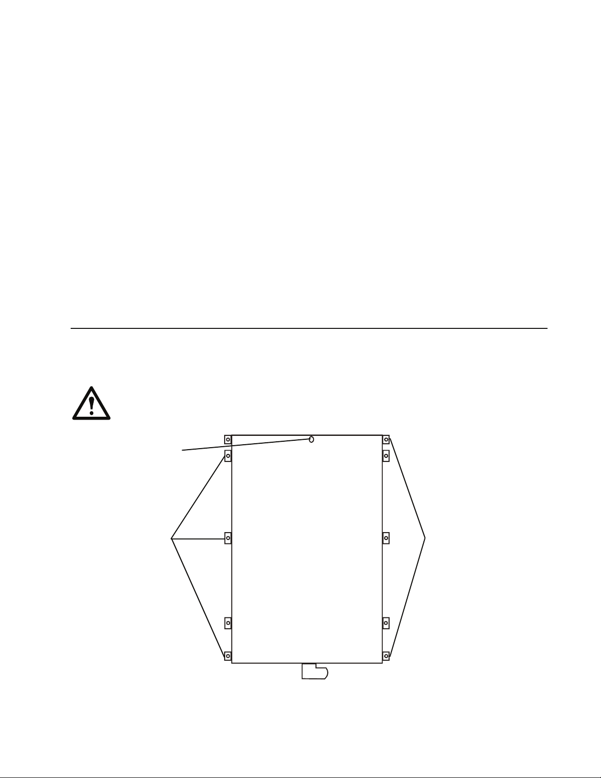
This unit is intended for wall mounting, either recessed into the wall for a flush mounting, or surface mounted on the wall.
The unit has built in tabs for mounting. Spacers are supplied in the accessories kit, for use in installations where the wall
will have wallboard applied after the UTS installation is complete.
Caution: The UTS must be installed within one foot of the building circuit breaker panel. If the UTS must
be located further than one foot from the circuit breaker panel, a licensed electrician must extend the wiring
using standard electrical wiring conduit and junction boxes.
eyelet for use during
surface wall mounting
tabs for surface
wall mounting
tabs for recessed
flush mounting

Site Preparation & Installation Guide Universal Transfer Switch UTS6 UTS6H UTS6BI UTS10BI8
Surface mount installation
1. Hang the UTS on a nail using the mounting eyelet located on the rear of the unit.
2. Locate two 16 inch on center wall studs within one foot of the building circuit breaker panel.
3. Mark the wall identifying the location of the mounting tabs.
4. Secure the UTS to the wall using six screws appropriate for the UTS weight and the wall material on which
the unit is being installed.
5. Proceed to the section in this manual, Connect UTS to circuit breaker panel.
Flush mount installation
1. Remove the six surface mounting tabs on the UTS using pliers to break the tabs off.
2. Remove the screws that secure the cover on the UTS, and remove the cover.
3. Locate two 16 inch on center wall studs within one foot of the building circuit breaker panel.
4. Mark the wall identifying the desired location for the UTS.
5. Cut an opening in the wall to accommodate the UTS, 21.3 in x 14.25 in (54.1 cm x 36.2 cm).
6. Mark the wall identifying the location of the mounting tabs.
7. Position the UTS in the opening. Secure the UTS to the wall using four screws appropriate for the UTS
weight and the wall material on which the unit is being installed.
Use spacers supplied in the accessories kit, for installations where the wall will have wallboard applied
after the UTS installation is complete.
8. Replace the UTS cover removed in Step 2.
9. Proceed to the section in this manual, Connect UTS to circuit breaker panel.
Connect UTS to circuit breaker panel
1. Disconnect power to the circuit breaker panel.
2. Remove the knockout on the building circuit breaker panel enclosure.
3. Insert the wires extending from the UTS flexible conduit, through the hole created by the knockout in the
circuit breaker panel enclosure.
4. Secure the flexible conduit using the locknut on the flexible conduit.
 Loading...