


 Loading...
Operation
Symmetra™ PX
48, 96, and 160 kW 400 V 100 kW 208 V
Legal Disclaimer
The information presented in this manual is not warranted by the Schneider Electric IT Corporation to be authoritative, error free, or complete. This publication is not meant to be a substitute for a detailed operational and site specific development plan. Therefore, Schneider Electric IT Corporation assumes no liability for damages, violations of codes, improper installation, system failures, or any other problems that could arise based on the use of this Publication.
The information contained in this Publication is provided as is and has been prepared solely for the purpose of evaluating data center design and construction. This Publication has been compiled in good faith by Schneider Electric IT Corporation. However, no presentation or warranty, either express or implied, is made as to the completeness or accuracy of the information this Publication contains.
IN NO EVENT SHALL SCHNEIDER ELECTRIC IT CORPORATION BE LIABLE FOR ANY DIRECT, INDIRECT, CONSEQUENTIAL, PUNITIVE, SPECIAL, OR INCIDENTAL DAMAGES (INCLUDING, WITHOUT LIMITATION, DAMAGES FOR LOSS OF BUSINESS, CONTRACT, REVENUE, DATA, INFORMATION, OR BUSINESS
INTERRUPTION) RESULTING FROM, ARISING OUT OF, OR IN CONNECTION WITH THE USE OF, OR INABILITY TO USE THIS PUBLICATION OR THE CONTENT, EVEN IF SCHNEIDER ELECTRIC IT CORPORATION HAS BEEN EXPRESSLY ADVISED OF THE POSSIBILITY OF SUCH DAMAGES. SCHNEIDER ELECTRIC IT CORPORATION RESERVES THE RIGHT TO MAKE CHANGES OR UPDATES WITH RESPECT TO OR IN THE CONTENT OF THE PUBLICATION OR THE FORMAT THEREOF AT ANY TIME WITHOUT NOTICE.
Copyright, intellectual, and all other proprietary rights of the content (including but not limited to software, audio, video, text, and photographs) rests with Schneider Electric IT Corporation or its licensors. All rights in the content not expressly granted herein are reserved. No rights of any kind are licensed or assigned or shall otherwise pass to persons accessing this information.
This Publication shall not be for resale in whole or in part.

Table of Contents
About this Manual.......................................................................................................... |
1 |
|
Companion Manuals ................................................................................................... |
1 |
|
Find Updates to this Manual ..................................................................................... |
1 |
|
Overview.............................................................................................................................. |
|
2 |
User Interface................................................................................................................ |
2 |
|
Display Interface........................................................................................................ |
3 |
|
Operation ............................................................................................................................ |
|
7 |
Modes.............................................................................................................................. |
|
7 |
Normal Operation ...................................................................................................... |
7 |
|
Battery Operation ...................................................................................................... |
7 |
|
Static Bypass Operation............................................................................................ |
7 |
|
Maintenance Bypass Operation (Optional) ................................................................ |
7 |
|
Operation Procedures ................................................................................................ |
7 |
|
Breakers/Switches in the System .............................................................................. |
7 |
|
Perform a Total Power Off.......................................................................................... |
8 |
|
Start the System after Total Power Off....................................................................... |
10 |
|
Turn the UPS Load Off............................................................................................... |
12 |
|
Turn the UPS Load On ............................................................................................... |
13 |
|
Transfer the UPS into Maintenance Bypass Operation .............................................. |
14 |
|
Return to Normal Operation from Maintenance Bypass Operation............................ |
16 |
|
View the Status Screens............................................................................................ |
19 |
|
View the Log Screen.................................................................................................. |
19 |
|
Configuration.................................................................................................................... |
20 |
|
System Settings ........................................................................................................... |
20 |
|
Set Up the Network.................................................................................................... |
20 |
|
Change the Display Interface Settings....................................................................... |
21 |
|
Change the Date and Time......................................................................................... |
22 |
|
Configure Input Contacts .......................................................................................... |
22 |
|
Configure Output Relays ........................................................................................... |
23 |
|
Maintenance |
...................................................................................................................... |
24 |
Life Cycle Monitoring (LCM) ..................................................................................... |
24 |
|
Parts Replacement ...................................................................................................... |
24 |
|
Determine if you Need a Replacement Part ............................................................... |
24 |
|
Return Parts to Schneider Electric ............................................................................ |
24 |
|
Replacement Parts .................................................................................................... |
26 |
|
Replace a Power Management Card .......................................................................... |
26 |
|
Replace a Power Module ........................................................................................... |
27 |
|
Replace a Battery....................................................................................................... |
28 |
|
Replace a Power Distribution Module........................................................................ |
31 |
|
990–3015E-001 |
Symmetra™ PX48, 96, and 160 kW 400 V 100 kW 208 V Operation |
i |

Troubleshooting.............................................................................................................. |
32 |
Status and Alarm Messages ..................................................................................... |
32 |
Display Messages...................................................................................................... |
32 |
Modular Distribution Fault List ................................................................................ |
36 |
PDU Fault List ............................................................................................................... |
37 |
ii |
Symmetra™ PX48, 96, and 160 kW 400 V 100 kW 208 V Operation |
990–3015E-001 |

About this Manual
This manual is for:
•Symmetra PX 48 kW 400 V UPS
•Symmetra PX 96 and 160 kW 400 V UPS and Power Distribution Unit (PDU-XR)
•Symmetra PX 100 kW 208 V UPS and Power Distribution Unit (PDU)
•XR Battery Enclosure
Companion Manuals
For additional information, see the following Symmetra PX manuals:
•Receiving and Unpacking (990-3013)
•Safety (990-2984)
•96 and 160 kW 400 V Installation (990-3017)
•48 kW 400 V Installation (990-3151)
•100 kW 208 V Installation (990-3659)
•48 kW 400 V XR Battery Enclosure (990-3190)
•Battery Replacement Sheet (990-2958)
Find Updates to this Manual
You can check for updates to this manual on www.apc.com. Look for the latest letter revision (A, B etc.) of the manual.
990–3015E-001 |
Symmetra™ PX48, 96, and 160 kW 400 V 100 kW 208 V Operation |
1 |

Overview
User Interface
|
|
|
|
|
|
|
|
|
|
|
|
|
|
|
|
|
|
|
|
|
|
|
|
|
|
|
|
|
|
|
|
|
|
|
|
|
|
|
|
|
|
|
|
|
|
|
|
|
|
|
|
|
|
|
|
|
|
|
|
|
|
|
|
|
|
|
|
|
|
|
|
|
|
|
|
|
|
|
|
|
|
|
|
|
|
|
|
|
|
|
|
|
|
|
|
|
|
|
|
|
|
|
|
|
|
|
|
|
|
|
|
|
|
|
|
|
|
|
|
|
|
|
|
|
|
|
|
|
|
|
|
|
|
|
|
|
|
|
|
|
|
|
|
|
|
|
|
|
|
|
|
|
|
|
|
|
|
|
|
|
|
|
|
|
|
|
|
|
|
|
|
|
|
|
|
|
|
|
|
|
|
|
|
|
|
|
|
|
|
|
|
|
|
|
|
|
|
|
|
A |
LOAD POWERED LED |
When this LED is green, power to the load is on. When the LED is |
|||||||||||||||||
|
|
|
|
|
|
yellow, the load is supplied through the batteries. When the LED is |
|||||||||||||
|
|
|
|
|
|
flashing yellow, the unit is in bypass. |
|||||||||||||
B |
CHECK LOG LED |
When this LED is green, a new event has been added to the event |
|||||||||||||||||
|
|
|
|
|
|
log. |
|||||||||||||
C |
WARNING LED |
When this LED is yellow, there are one or more warning alarms |
|||||||||||||||||
|
|
|
|
|
|
in the system. |
|||||||||||||
D |
CRITICAL LED |
When this LED is red, there are one or more critical alarms in the |
|||||||||||||||||
|
|
|
|
|
|
system. |
|||||||||||||
E |
LCD SCREEN |
Displays alarms, status data, instructional help, and configuration |
|||||||||||||||||
|
|
|
|
|
|
items. |
|||||||||||||
F |
UP AND DOWN NAVIGATION |
Used to scroll through and select menu items. |
|||||||||||||||||
|
KEYS |
|
|
|
|
|
|
|
|
|
|
|
|
|
|
||||
G |
ENTER KEY |
Opens menu items and confirms changes to the system parameters. |
|||||||||||||||||
|
|
|
|
|
|
|
|
|
|
|
|
|
|
|
|
|
|
|
|
H |
HELP KEY |
Opens context-sensitive help. |
|||||||||||||||||
|
|
|
|
|
|
|
|
|
|
|
|
|
|
|
|
|
|
|
|
I |
ESC KEY |
Returns to the previous screen displayed. |
|||||||||||||||||
|
|
|
|
|
|
|
|
|
|
|
|
|
|
|
|
|
|
|
|
2 |
Symmetra™ PX48, 96, and 160 kW 400 V 100 kW 208 V Operation |
990–3015E-001 |
Display Interface
Overview Screens
The Overview Screen is the main entrance to the user functions of the display interface. The UP/DOWN navigation keys take you from one screen to another. When the system is running, the display will scroll through screens showing information about the system and any active alarms.
Note: The data values shown are for example only.
No Active Alarms
System Date/Time: 28-Mar-2010 10:37:01
Volts In |
Volts |
Out |
L1: xxx |
L1: xxx |
|
L2: xxx |
L2: xxx |
|
L3: xxx |
L3: xxx |
|
|
|
|
Out Amps |
kW |
kVA |
L1: xxx |
xx.x |
xx.x |
L2: xxx |
xx.x |
xx.x |
L3: xxx |
xx.x |
xx.x |
Symmetra PX 160 kW
Runtime: xxhr xxmin
Capacity xxx.x%
UPS Load: xxx%
System Bypass State:
UPS Operation
UPS State:
On Line
Note: Press ENTER to go from any overview screen to the main menu screen.
990–3015E-001 |
Symmetra™ PX48, 96, and 160 kW 400 V 100 kW 208 V Operation |
3 |

Main Menu Screen
From the main menu it is possible to configure and monitor the system through the sub menu screens:
UPS, Power Dist, Switchgear, Environment, Alarms, Log, Admin, and Help. Use the UP and DOWN arrow keys to navigate through the menu screens.
Main Screen |
System Bypass State: |
|
UPS Operation |
|
UPS State: |
|
On Line |
4 |
Symmetra™ PX48, 96, and 160 kW 400 V 100 kW 208 V Operation |
990–3015E-001 |

Menu Tree
The menu tree provides a quick overview of the functions and views you may access.
|
|
|
UPS Power Control |
|
|
|
|
|
|
UPS |
UPS Status |
|
|
|
|
|
|
|
UPS Tests & Diags |
|
|
|
|
|
|
|
UPS Configuration |
|
|
|
|
|
|
|
|
|
|
|
Total Loading |
|
|
|
|
|
|
Power Dist |
Modular Loading |
|
|
|
|
|
|
|
Volt-Meter |
|
|
|
Subfeeds |
|
|
|
|
|
|
|
|
|
|
Switchgear |
Status |
|
|
|
|
|
|
|
Factory |
|
|
|
|
|
|
|
|
|
|
|
Input Contacts |
|
|
|
|
|
|
Environment |
Output Relays |
|
|
|
|
|
|
|
Alarm Relay Map |
|
|
|
|
|
|
|
Env Monitoring Card |
|
|
|
|
|
|
|
|
Main Menu Screen |
|
Alarms |
All Active Alarms |
|
|
|
|
|
|
Active by Severity |
|
|
|
|
|
|
|
|
|
|
|
|
Active by Type |
|
|
Log |
|
|
|
|
|
|
|
View New Log Items |
|
|
|
|
|
|
|
|
View Entire Log |
|
|
|
|
|
|
|
Clear Entire Log |
|
|
|
|
|
|
|
|
|
|
|
Network Setup |
|
|
|
|
|
|
Admin |
Local Interface |
|
|
|
|
|
|
|
Date/Time |
|
|
|
|
|
|
|
Device ID |
|
|
|
|
|
|
|
Manufacturer Data |
|
|
|
|
|
|
|
Factory Defaults |
|
|
|
|
|
|
|
Firmware Upgrade |
|
|
|
|
|
|
|
Life cycle Monitor |
|
|
|
|
|
|
|
|
|
|
|
On any screen |
|
|
|
& any line, press ‘?’ for context |
|
|
Help |
sensitive help. Try it now... |
990–3015E-001 |
Symmetra™ PX48, 96, and 160 kW 400 V 100 kW 208 V Operation |
5 |

Caution: The display provides access to more functions than described in this manual. Those functions should not be accessed without the assistance of Schneider Electric Customer Support in order to avoid unwanted load impacts. For Schneider Electric World-Wide Customer Support, refer to the back cover of this manual. If you by accident go beyond the functions described, press ESC to return to previous screens.
6 |
Symmetra™ PX48, 96, and 160 kW 400 V 100 kW 208 V Operation |
990–3015E-001 |
Operation
Modes
In an installation that does not include a maintenance bypass panel, the UPS has three operation modes: normal operation, battery operation and static bypass operation. If the installation includes a PDU, a PDU-XR, or an external maintenance bypass panel, the mode maintenance bypass operation also becomes available.
Normal Operation
During normal operation, the UPS converts the utility/mains supply to conditioned power for the connected load.
Battery Operation
During battery operation, the UPS provides conditioned power to the connected load from its batteries for a finite period. The UPS transfers to battery operation if the utility/mains power supply fails or is outside pre-defined limits.
Static Bypass Operation
Static bypass operation is a feature that keeps the load supplied directly from the utility/mains supply during different scenarios on the UPS or downstream from the UPS. In static bypass operation, the utility/mains is supplying power to the connected load directly, bypassing all internal UPS functions.
Maintenance Bypass Operation (Optional)
The UPS can be connected to a PDU, a PDU-XR, or an optional external maintenance bypass panel that enables the user to bypass the UPS completely for maintenance purposes that might even include replacement of the entire UPS. The connected load will then be fed directly from the utility/mains supply, and there will in this case be no filtering of the supply or battery backup of the load.
Operation Procedures
Breakers/Switches in the System
Q1 UPS input
Q2 UPS output
Q3 Maintenance Bypass
Q5 Static Bypass input (only in dual utility/mains systems)
Note: If the system does not contain a PDU or PDU-XR, the Q1, Q2, and Q3 switches and the Q5 breaker should be located in an optional external maintenance bypass panel. See the documentation included with the maintenance bypass panel for additional information.
990–3015E-001 |
Symmetra™ PX48, 96, and 160 kW 400 V 100 kW 208 V Operation |
7 |
Perform a Total Power Off
WARNING: This procedure will disconnect the load.
Note: If shutdown via the display is disabled, then you cannot perform this procedure and the message: Command not allowed, UPS configured to never shutdown appears. If you want to enable shutdown via the display, this is done by a Field Service Engineer via the UPSTuner.
1. Select UPS and press ENTER.
→ UPS |
Alarm |
Power Dist |
Log |
Switch Gear |
Admin |
Environment |
Help |
2. Select UPS Power Control and press ENTER.
→ UPS Power Control
UPS Status
UPS Tests & Diags
UPS Configuration
3. Select Turn UPS Off and press ENTER.
→ Turn UPS Off Reboot UPS
UPS into Bypass UPS to Sleep
4.Select No, Don’t Notify to shut down without delay and press ENTER.
Note: This action will cut all power to the load without shutting it down first. If you want to shut down the servers first, then choose Yes, Notify Servers. Note that this function
is only available for servers with PowerChute.
5.Confirm YES, Turn UPS Off and press ENTER.
6. Wait for the UPS to turn off.
Notify PowerChute ?
Cancel
Yes, Notify Servers
→ No, Don't Notify
Turn UPS off Without Server Notification? > NO, ABORT
→> YES, Turn UPS Off
Turning UPS off,
please wait...
8 |
Symmetra™ PX48, 96, and 160 kW 400 V 100 kW 208 V Operation |
990–3015E-001 |

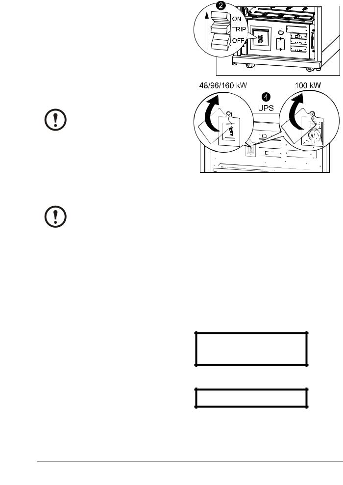
7. Set the UPS SYSTEM ENABLE switch to the OFF position.
8. Set the Q2 switch to the OFF position.
9. Set the Q1 switch to the OFF position.
10. Set the Q5 breaker to the OFF position (if applicable).
11. Verify that the maintenance bypass switch
(Q3) is in the OFF position.
12. Set the DC DISCONNECT switch on all of |
XR Battery Enclosures/PDU-XR |
the XR Battery Enclosures and the PDU-XR |
|
(if applicable) and on the main frame (only for |
|
PX48) to the OFF position. |
|
13.Disconnect all battery units by removing them or pulling them out to the red disconnect line.
Caution: To ensure that the enclosure does not tip, do not pull out the battery units beyond the red disconnect line. If you intend to completely remove the battery units, remove them from the enclosure one at a time. Failure to pull battery units out to the red disconnect line could cause deep discharge/damage to the batteries.
14. Set the upstream mains power to the OFF or LOCKED OUT position. If the UPS has a dual mains supply, set both supplies to the OFF or LOCKED OUT position.
15.Measure bypass/output DC and mains to ensure that the system is completely powered off.
990–3015E-001 |
Symmetra™ PX48, 96, and 160 kW 400 V 100 kW 208 V Operation |
9 |
Start the System after Total Power Off
1.Set the upstream utility/mains power to the ON or LOCKED IN position. If the UPS has a dual mains supply, set both supplies to the ON or LOCKED IN position.
2.Set the DC DISCONNECT switch to the ON position on all XR Battery Enclosures and the PDU-XR (if applicable) and on the main frame (only PX 48).
3.Set the Q1 switch to the ON position.
4.Set the SYSTEM ENABLE switch on the UPS to the ON position.
Note: Wait approximately two minutes for the system to start.
5.Set the Q5 breaker to the ON position (if applicable).
Note: The H2 LED next to the Q2 switch will turn on, indicating that it is safe to operate the Q2 switch.
6.Set the Q2 switch on the PDU, PDU-XR or the external maintenance bypass panel to the ON position.
7.Select UPS and press ENTER.
8. Select UPS Power Control and press ENTER.
XR Battery Enclosures/PDU-XR
→ UPS |
Alarms |
Power Dist |
Log |
Switch Gear |
Admin |
Environment |
Help |
→ UPS Power Control
UPS Status
UPS Tests & Diags
UPS Configuration
9. Select Turn UPS On and press ENTER.
→ Turn UPS On
UPS On Into Bypass
10 |
Symmetra™ PX48, 96, and 160 kW 400 V 100 kW 208 V Operation |
990–3015E-001 |
Loading...