


SmartSlot
Table of contents
 Loading...
Thank You!
Thank
y
ou for selectin
g
the American Power Conversion SmartSlot Series
Measure-UPS II. It has been desi
g
ned for man
y
y
ears of reliable, mainte-
nance-free service. Please read this manual! It provides installation and
operatin
g
instructions that will help
y
ou
g
et the most from
y
our accessor
y
.
Save this manual! It includes important instructions for the safe installa-
tion of
y
our accessor
y
. Further, it includes instructions for obtainin
g
fac-
tor
y
service.
Radio frequency interference
WARNING:
Chan
g
es or modifications to this unit not expressl
y
approved b
y
the part
y
responsible for compliance could void the users
authorit
y
to operate the equipment.
NOTE:
This equipment has been tested and found to compl
y
with the
limits for a Class A di
g
ital device pursuant to Part 15 of the FCC Rules.
These limits are desi
g
ned to provide reasonable protection a
g
ainst harm-
ful interference when the equipment is operated in a commercial environ-
ment. This equipment
g
enerates, uses, and can radiate radio frequenc
y
ener
gy
and, if not installed and used in accordance with the instruction
manual, ma
y
cause harmful interference to radio communications. Opera-
tion of this equipment in a residential area is likel
y
to cause harmful inter-
ference in which case the user will be required to correct the interference
at his own expense.
This di
g
ital apparatus does not exceed the Class A limits for radio noise
emissions from di
g
ital apparatus set out in the Radio Interference Re
g
ula-
tions of the Canadian Department of Communications.
Le présent appareil numérique n’émet pas de bruits radioélectriques
dépassant les limites applicables aux appareils numériques de la Class A
prescrites dans le Rè
g
lement sur le brouilla
g
e radioélectrique édicté par le
ministère des Communications du Canada.
Entire contents co
py
ri
g
ht © 1995 American Power Conversion. All ri
g
hts
reserved. Re
p
roduction in whole or in
p
art without written
p
ermission is
p
ro-
hibited. PowerChute is a re
g
istered trademark of APC. SmartSlot, PowerNet,
Call-UPS, and the st
y
lized APC lo
g
o are trademarks of APC. All other trade-
marks are
p
ro
p
ert
y
of their res
p
ective owners.

Contents
1 Introduction . . . . . . . . . . . . . . . . . . . . . . . . . . . . . . . . . . . . . . . . .1
2 Installation . . . . . . . . . . . . . . . . . . . . . . . . . . . . . . . . . . . . . . . . . .3
3 Operation Check. . . . . . . . . . . . . . . . . . . . . . . . . . . . . . . . . . . . . .5
4 Sensor Zone Connections. . . . . . . . . . . . . . . . . . . . . . . . . . . . . . .6
5 Sensor Selection . . . . . . . . . . . . . . . . . . . . . . . . . . . . . . . . . . . . . .8
6 Maintenance . . . . . . . . . . . . . . . . . . . . . . . . . . . . . . . . . . . . . . . . .9
7 Troubleshootin
g
. . . . . . . . . . . . . . . . . . . . . . . . . . . . . . . . . . . . .10
8 Service . . . . . . . . . . . . . . . . . . . . . . . . . . . . . . . . . . . . . . . . . . . .11
9 Specifications . . . . . . . . . . . . . . . . . . . . . . . . . . . . . . . . . . . . . . .12
10 Declaration of Conformit
y
. . . . . . . . . . . . . . . . . . . . . . . . . . . . .13
11 Index. . . . . . . . . . . . . . . . . . . . . . . . . . . . . . . . . . . . . . . . . . . . . .14
1. Introduction
The SmartSlot Measure-UPS II performs temperature and humidit
y
sensin
g
, as well as contact monitorin
g
.
Measure-UPS II supports up to four zones of contact monitorin
g
, each
of which supports both normall
y
open and normall
y
closed contacts.
Measure-UPS II reports temperatures from 0 to 60 °C (32 to 140 °F)
and relative humidit
y
from 10 to 90%.
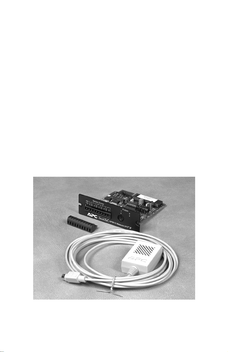
Measure-UPS II model AP9612T includes:
• Measure-UPS
II
SmartSlot UPS accessory
• Temperature probe (model AP9512T)
• Screw terminal connector for contact monitoring
• Hook and loop probe fasteners.
Measure-UPS II model AP9612TH includes:
• The Measure-UPS
II
SmartSlot UPS accessory
• Combined temperature and humidity probe (model
AP9512TH)
• Screw terminal connector for contact monitoring
• Hook and loop probe fasteners.
Figure 1, SmartSlot Measure-UPS II

Safety Notice
The SmartSlot Measure-UPS II UPS accessor
y
is intended solel
y
for
use in supplementar
y
surveillance of equipment. APC does not recom-
mend this product for life or propert
y
protection. APC will not know-
in
g
l
y
sell Measure-UPS II for use in such applications. APC disclaims
all liabilit
y
arisin
g
out of improper use of Measure-UPS II as
described herein.
Hardware and Software Compatibility
SmartSlot Measure-UPS II requires an APC device with a SmartSlot
as a host. This can be a UPS equipped with a SmartSlot, or a Smart-
Slot Expansion Chassis in combination with a UPS that supports the
Expansion Chassis.
Measure-UPS II also requires some means of reportin
g
its data. This
can be an
y
one or a combination of the followin
g
:
• Call-UPS
II
™ Remote UPS Management Device
•PowerChute
®
Plus UPS power management and diagnostic
software
• PowerNet SNMP adapter
• PowerNet SNMP agent.
Note
: An
y
SNMP mana
g
ement s
y
stem can read and use Measure-
UPS II information when it is installed in con
j
unction with an APC
PowerNet SNMP adapter or PowerNet SNMP a
g
ent. PowerNet
SNMP Mana
g
er provides a hi
g
h level
g
raphical user interface for use
within popular network mana
g
ement s
y
stems. Contact APC at the
number on the back cover of this manual for more information.
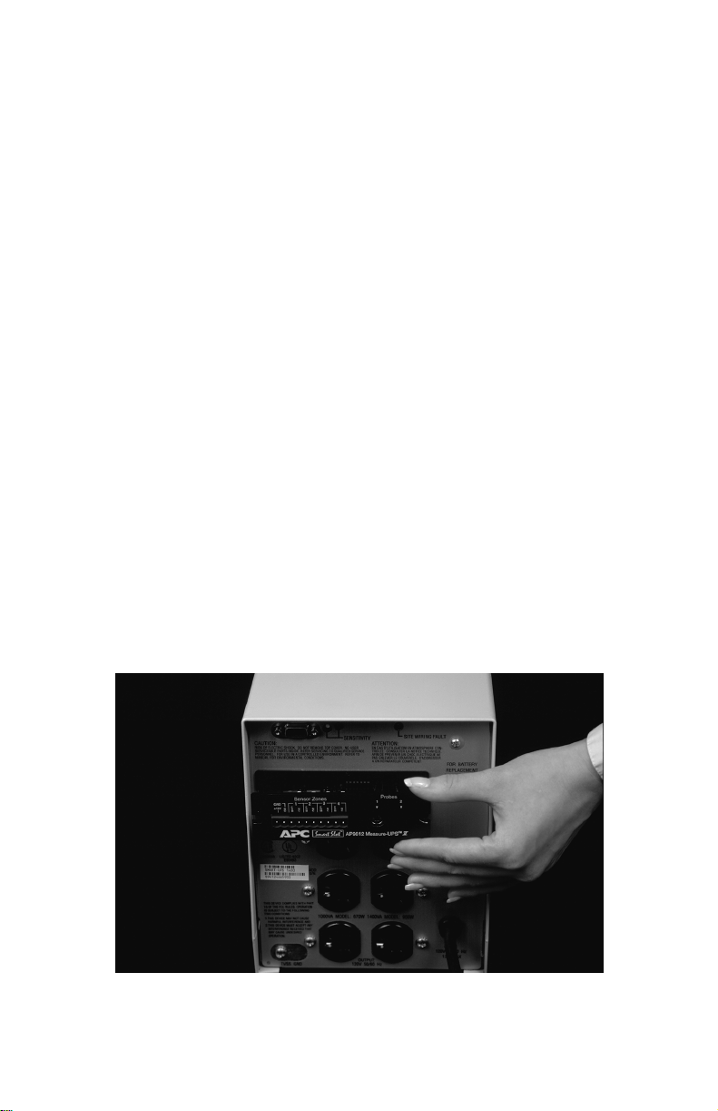
2. Installation
Use the followin
g
procedure to install SmartSlot Measure-UPS II:
1. Install and configure any software or hardware that will be used
with Measure-UPS
II
for data reporting (see software and hard-
ware compatibility above).
2. Using figure 2 as a guide, install Measure-UPS
II
in the host
SmartSlot. Use a #2 Phillips head screwdriver to remove the host
device SmartSlot cover plate. Install Measure-UPS
II
. Replace the
cover plate screws. Note: Measure-UPS
II
is sensitive to static
electricity. Handle Measure-UPS
II
by the end plate only. Do not
touch the exposed printed circuit board. While it is not possible to
install Measure-UPS
II
upside down, it is possible to damage it in
the attempt. Note that the edges of the printed circuit board align
with the locating slots in the sides of the SmartSlot. The Smart-
Slot may be oriented horizontally or vertically in the host device.
The host device may be on or off during installation.
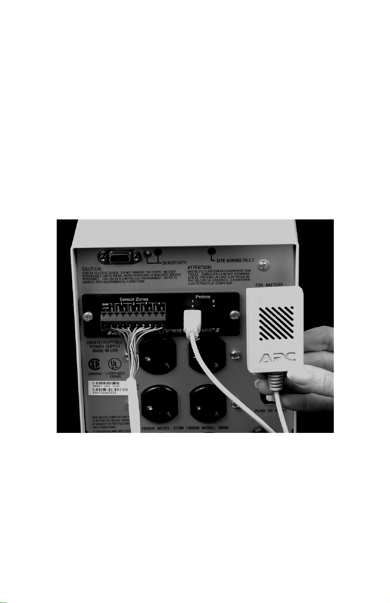
3. Connect the supplied probe to probe connector 1 on Measure-
UPS
II
.
Note
: probe connector 2 is not used in Measure-UPS
II
.
4. Place the probe where desired using the supplied hook and loop
fasteners, if needed. Note: The Measure-UPS
II
probe is designed
for use in a controlled environment. Place it in an area that is
within the environment limits set in the specifications (see section
9.) The location must be free from direct sunlight, excessive
moisture, and dust.
Figure 2, SmartSlot installation
Do not:
• Cover any of the ventilation holes on the probe
• Immerse the probe or place it where dew can be expected to
form
• Use the probe in an environment with chlorine gas or insecti-
cides.
5. The contact monitoring connection is a two piece design. Connect
contact closure-type sensors to the removable screw terminal
block using the information in section 4 as a guide. The connector
accepts wire sizes from 14 AWG (1.6 mm2) to 26 AWG (.4
mm2). Strip the wire insulation 0.25" (6 mm). Connect the screw
terminal block to the Sensor Zones connector of Measure-UPS
II
.
See fi
g
ure 3 below for a completed installation.
Figure 3, completed installation
Loading...