


User Manual
English
APC Smart-UPS
1500/3000 VA 120/230 Vac
Modular
Uninterruptible Power Supply
990-1704 01/2004
Introduction
This APC Smart-UPS is a modular Uninterruptible Power Supply (UPS) for high availability applications such as data centers and mission critical processes, designed to prevent blackouts, brownouts, sags, and surges from reaching your equipment. The UPS filters small utility line fluctuations and isolates your equipment from large disturbances by internally disconnecting from the utility line. The UPS provides continuous power from its internal battery until the utility line returns to safe levels or the battery is fully discharged.
1: INSTALLATION
The User Manual and Safety Guide are accessible on the supplied User Manuals CD and on the APC web site, www.apc.com.
Unpack
Attention: Read the safety instruction sheet before installation.
Inspect the UPS upon receipt. Notify the carrier and dealer if there is damage. The packaging is recyclable; save it for reuse or dispose of it properly. Check the package contents:
UPS
Bezel
Tower conversion top panels and mounting stabilizers
Rail kit
UPS literature kit containing:
|
Product documentation, safety, |
Serial and USB communication |
|
and warranty information |
cables |
Smart-UPS User Manuals CD |
230 V models only: |
|
|
PowerChute® CD |
Two input power cords |
Network Management Card CD |
Four output jumper cords |
|
|
Mounting hardware |
|
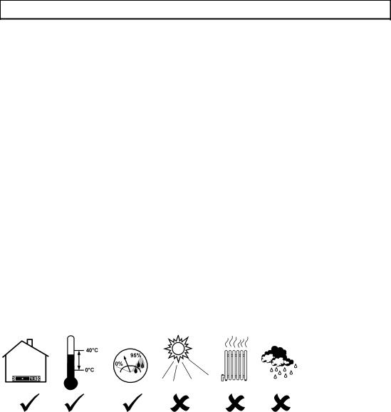
Position the UPS in the Specified Environment
0-40°C
0-95%
1

Mount the UPS in the Rack and Connect the Battery
Attention: Install the rails following the instructions in the rail kit.
|
|
|
|
|
Rear |
2
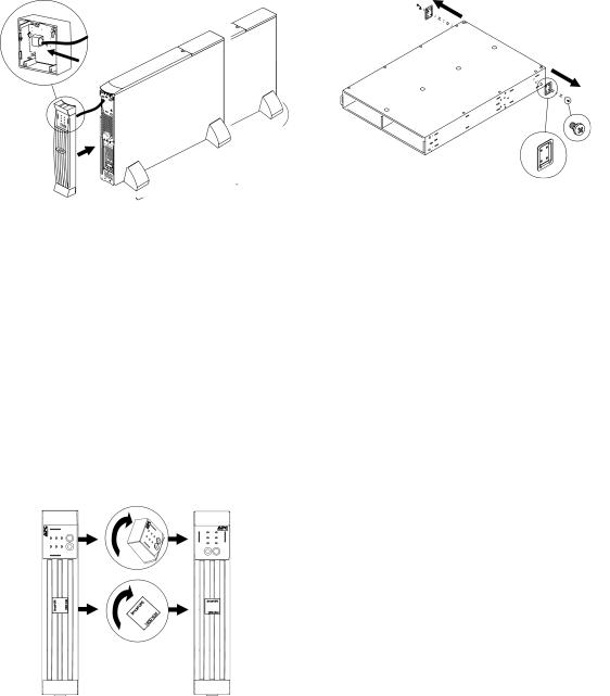
Tower Configuration
Press and hold the black switch (see location
designation on UPS) to the right while removing the power processing module.
Snap the display bezel out the rear to begin rotation.
Note: Place the UPS in the final operating location prior to module reinstallation.
Rear
3
2: START UP
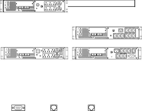
Connect Equipment to the UPS
Rear Panels |
|
1500 VA, 120 V: |
1500 VA, 230 V: |
3000 VA, 120 V: |
3000 VA, 230 V: |
Note:
•The ‘outlet groups’ can be controlled through the network software. See Network Management Card documentation.
•A laser printer draws significantly more power than other types of equipment and may overload the UPS.
Connect the UPS to the Network (if Applicable)
Network Connectors |
|
|
Serial Port |
USB Port |
Ethernet Port |
Note:
•Use only the supplied cable to connect to the Serial Port. A standard serial interface cable is incompatible with the UPS. Serial and USB ports cannot be used simultaneously.
•If an optional Smart-Slot accessory is to be used, remove the preinstalled network management card and install it now.
Start the UPS
Attention: Upon utility power connection, the UPS will automatically turn on.
1.Plug the UPS into a two-pole, three-wire, grounded receptacle only. Input Plugs:
1500 VA models: 120 V = NEMA 5-15P; 230 V = Use country specific 10 A with C14 input cords (not supplied).
3000 VA models: 120 V = NEMA L5-30P; 230 V = Use the supplied cords or the country specific equivalent.
4
 Loading...