


 Loading...
Installation
Smart-UPS® VT
XR Battery Enclosure
10-40 kVA 380/400/415 V
10-30 kVA 208/220 V
10-30 kVA 200/208 V


Contents
Safety ............................................................................... |
1 |
IMPORTANT SAFETY INSTRUCTIONS
- SAVE THESE INSTRUCTIONS . . . . . . . . . . . . . . . . . . . . . . . . . . . . . . 1
Prepare for Floor-Anchoring (optional) ........................ |
2 |
System arrangements . . . . . . . . . . . . . . . . . . . . . . . . . . . . . . . . . . . . |
2 |
Hole positions for a stand-alone UPS enclosure with L-shaped |
|
anchoring brackets . . . . . . . . . . . . . . . . . . . . . . . . . . . . . . . . . . . . . . . |
3 |
Hole positions for up to four UPS units in parallel with U-shaped |
|
anchoring brackets. . . . . . . . . . . . . . . . . . . . . . . . . . . . . . . . . . . . . . . 4 |
|
Prepare for Cables .......................................................... |
5 |
Remove the front panel . . . . . . . . . . . . . . . . . . . . . . . . . . . . . . . . . . . |
5 |
Remove the top cover . . . . . . . . . . . . . . . . . . . . . . . . . . . . . . . . . . . . |
5 |
Remove the cable landing cover and bottom plates . . . . . . . . . . . . |
6 |
Remove the XR Battery Modules . . . . . . . . . . . . . . . . . . . . . . . . . . . |
7 |
Anchor the UPS and additional XR Battery or
UPS Enclosure(s) (optional). . . . . . . . . . . . . . . . . . . . . . . . . . . . . . . . . 8
Run the Cables.............................................................. |
11 |
Connect Power in Installations with Busbars . . . . . . . . . . . . . . . . . 11
Install isolators . . . . . . . . . . . . . . . . . . . . . . . . . . . . . . . . . . . . . . . . . 11
Install busbars . . . . . . . . . . . . . . . . . . . . . . . . . . . . . . . . . . . . . . . . . 12
Connect Power in Installations with Cables. . . . . . . . . . . . . . . . . . . 16
Install power cables . . . . . . . . . . . . . . . . . . . . . . . . . . . . . . . . . . . . . 16
Connect Communication Cables. . . . . . . . . . . . . . . . . . . . . . . . . . . . 18
Connect the EPO. . . . . . . . . . . . . . . . . . . . . . . . . . . . . . . . . . . . . . . . . 19
Connect the EPO to the UPS and the XR Battery Enclosure . . . . 19
Smart-UPS VT ® 10-40 kVA 380/400/415 V, 208/220 V, 200/208 V Battery Installation |
i |
Final Mechanical Assembly.......................................... |
20 |
Level the Enclosures (L-shaped Floor Anchoring Brackets)
and Install Batteries . . . . . . . . . . . . . . . . . . . . . . . . . . . . . . . . . . . . . . 20
Level the enclosures . . . . . . . . . . . . . . . . . . . . . . . . . . . . . . . . . . . . . 20
Install battery-securing and floor-anchoring brackets . . . . . . . . . 21
Reinstall the Enclosure Plates . . . . . . . . . . . . . . . . . . . . . . . . . . . . . 22
Reinstall the cable landing cover plates and the bottom plates . . |
22 |
Reinstall the top cover, battery compartment cover, |
|
and the front panel . . . . . . . . . . . . . . . . . . . . . . . . . . . . . . . . . . . . . . |
22 |
Specifications ................................................................ |
23 |
Battery voltage and current . . . . . . . . . . . . . . . . . . . . . . . . . . . . . . . 23
Recommended cable sizes . . . . . . . . . . . . . . . . . . . . . . . . . . . . . . . . 23
EPO requirements . . . . . . . . . . . . . . . . . . . . . . . . . . . . . . . . . . . . . . . 23
Torque specification . . . . . . . . . . . . . . . . . . . . . . . . . . . . . . . . . . . . . 23
Post-Installation Checklist............................................ |
24 |
ii |
Smart-UPS VT ® 10-40 kVA 380/400/415 V, 208/220 V, 200/208 V Battery Installation |

Safety
IMPORTANT SAFETY INSTRUCTIONS - SAVE THESE INSTRUCTIONS
Warning:
• ALL safety instructions in the Safety Sheet (990-2822) must be read, understood, and followed when installing the UPS system. Failure to do so could result in equipment damage, serious injury, or death.
•The UPS system does not have built-in disconnection devices for AC input/output and DC input. The customer must provide AC input/output over-current protection and an AC output disconnect device.
•After the UPS has been electrically wired, do not start it. Start-up is commissioned to authorized personnel from Schneider Electric only.
Smart-UPS VT ® 10-40 kVA 380/400/415 V, 208/220 V, 200/208 V Battery Installation |
1 |

Prepare for Floor-Anchoring (optional)
Note: If floor anchoring and battery securing is required, read this section. If not, see “Prepare for Cables” on page 5.
Note: Allow for enough working space behind the enclosure for electrical work to be carried out (e.g. if you want to install a conduit box or if you want to connect an XR Battery Enclosure at a later stage). Minimum rear clearance is 100 mm (3.93 in) and must comply with applicable national and local codes. 600 mm (23.6 in) is recommended.
Note: The L-shaped floor anchoring brackets that secured the enclosure to the pallet during shipment may be used for a stand-alone UPS enclosure to enhance stability. See this chapter for hole positions and see also “Level the Enclosures (L-shaped Floor Anchoring Brackets) and Install Batteries” on page 20. The L-shaped floor anchoring brackets are not necessary when baying enclosures together. Instead, the three U-shaped floor anchoring brackets from the baying kit are used.
Note: Hole positions are only intended as a guide.
System arrangements
APC recommends the following arrangements of UPS units and XR Battery Enclosures (XR) in parallel.
Examples with two parallel systems using baying kits.
UPS |
XR |
XR |
XR |
XR |
UPS |
XR |
XR |
XR |
XR |
|
UPS |
XR |
XR |
XR |
XR |
|
UPS |
XR |
XR |
XR |
XR |
|
|
|
|
|
|
|
|
|
|
|
|
|
|
|
|
|
|
|
|
|
|
|
|
|
|
|
|
|
|
|
|
|
|
|
|
|
|
|
|
|
|
|
|
XR |
XR |
XR |
XR |
UPS |
UPS |
XR |
XR |
XR |
XR |
|
|
|
|
|
|
|
|
|
|
|
|
|
|
|
|
|
|
|
|
|
|
|
|
|
|
|
|
|
|
|
|
|
|
2 |
Smart-UPS VT ® 10-40 kVA 380/400/415 V, 208/220 V, 200/208 V Battery Installation |
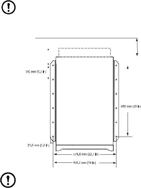
Hole positions for a stand-alone UPS enclosure with L-shaped anchoring brackets
Note: Recommended minimum number of screws per enclosure for the L-shaped brackets is four; one in each corner. Recommended floor bolt size: M8.
Model width: 352 mm (13.85 in) and 523 mm (20.59 in).
|
|
|
|
|
|
|
|
|
Minimum rear |
|
|
|
|
|
|
|
|
|
clearance: |
|
|
Conduit box (if applicable) |
|
|
|
100 mm (3.93 in) |
|||
|
|
|
|
|
|
|
|
|
|
|
|
|
|
|
|
|
|
|
|
|
|
|
|
|
|
|
|
Floor anchoring hole |
|
|
|
|
|
|
|
|
|
|
|
|
|
|
|
|
|
|
|
|
|
|
|
|
|
|
|
|
|
|
|
|
|
|
|
|
|
|
|
|
|
|
|
|
|
|
|
|
|
|
|
523 mm (20.59 in)
352 mm (13.85 in ) enclosure
Note: Rear service clearance must comply with applicable national and local codes. 600 mm (23.6 in) is recommended.
Smart-UPS VT ® 10-40 kVA 380/400/415 V, 208/220 V, 200/208 V Battery Installation |
3 |
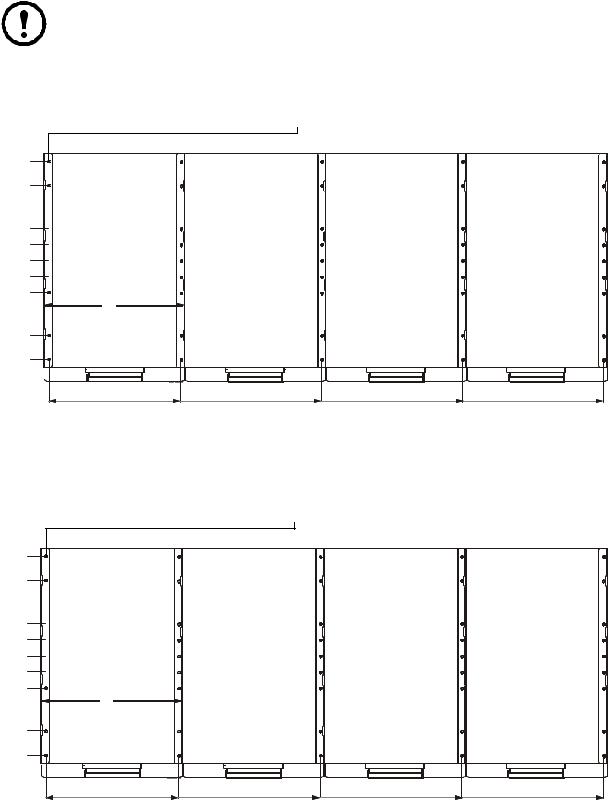
Hole positions for up to four UPS units in parallel with U-shaped anchoring brackets.
Note: Recommended minimum number of floor screws for the below two configurations is 10.
Model width: 352 mm (13.85 in).
90 mm (3.54 in)
160 mm (6.29 in)
60 mm (2.36 in) 
60 mm (2.36 in) 
60 mm (2.36 in) 
60 mm (2.36 in) 
160 mm (6.29 in)
90 mm (3.54 in)
Top view |
|
|
|
|
|
|||
|
Floor anchoring brackets |
|||||||
|
|
|
|
|
|
|
|
|
|
|
|
|
|
|
|
|
|
|
|
|
|
|
|
|
|
|
|
|
|
|
|
|
|
|
|
|
|
|
|
|
|
|
|
|
in) 85.(13 mm 352
0 |
323 mm |
675 mm |
1027 mm |
1379 mm |
|
(12.71 in) |
(26.56 in) |
(40.41 in) |
(54.26 in) |
Model width: 523 mm (20.59 in).
90 mm (3.54 in)
160 mm (6.29 in)
60 mm (2.36 in) 
60 mm (2.36 in) 
60 mm (2.36 in) 
60 mm (2.36 in) 
160 mm (6.29 in)
90 mm (3.54 in)
0
Top view |
|
Floor anchoring brackets |
|
|
|||||
|
|
|
|
|
|
|
|
|
|
|
|
|
|
|
|
|
|
|
|
|
|
|
|
|
|
|
|
|
|
|
|
|
|
|
|
|
|
|
|
in) 59.(20 mm 523
494.5 mm |
1017.5 mm |
1540.5 mm |
2063.5 mm |
(19.46 in) |
(40.05 in) |
(60.46 in) |
(81.23 in) |
4 |
Smart-UPS VT ® 10-40 kVA 380/400/415 V, 208/220 V, 200/208 V Battery Installation |

Prepare for Cables
Remove the front panel
1. Turn the screw to the right to the unlocked position.
2. |
Pull the top of the front |
|
|
panel away from the |
|
|
UPS. |
|
3. |
Lift the front panel free |
|
|
of the two slots at the |
|
|
|
|
|
bottom of the enclosure. |
|
4.Lift the battery compartment cover free
of the two slots at the bottom of the enclosures (only in Japanese configurations).
|
|
|
Remove the top cover |
|
|
1. Loosen the six screws of the top |
UPS front view |
XR Battery |
cover (four at the front and two at |
|
Enclosure |
the back). |
|
|
2. Lift up from the back and push forward to free the cover.
Smart-UPS VT ® 10-40 kVA 380/400/415 V, 208/220 V, 200/208 V Battery Installation |
5 |
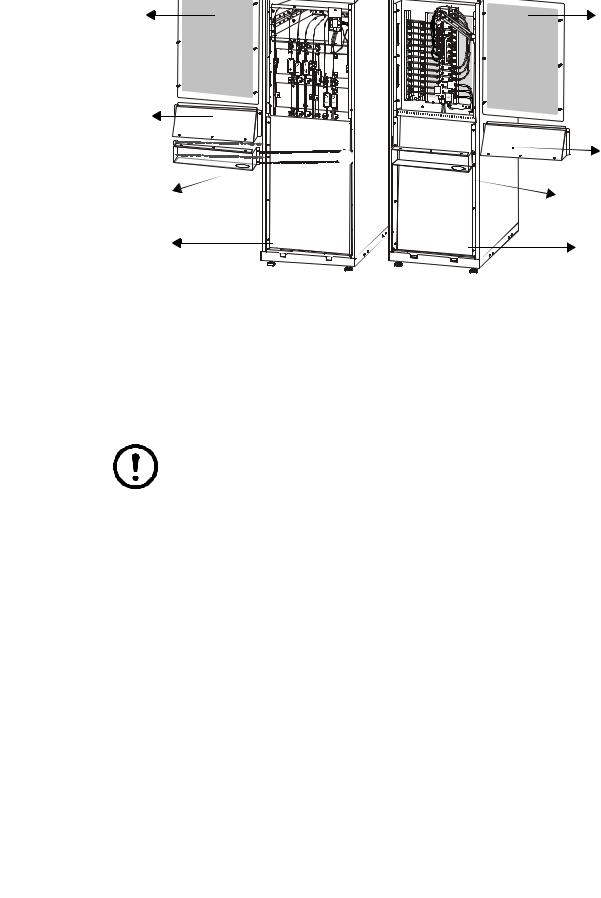
Remove the cable landing cover and bottom plates
To access the cable landing area in the UPS and the XR Battery Enclosure(s), follow this procedure:
|
Cable |
Cable |
|
landing |
landing |
|
cover plate |
|
|
cover |
|
|
|
|
|
|
plate |
|
|
+ |
|
|
N |
Conduit |
Conduit |
|
|
box (upper |
Box |
|
part) |
(upper |
|
|
part) |
Conduit box |
Conduit box |
|
|
(bottom part) |
(bottom part) |
Bottom plate |
Bottom plate |
|
1.Loosen the six M4 screws from the cable landing cover plate on the UPS and the XR Battery Enclosure(s) and then remove the plates.
2.Remove the screws from the bottom plate on the UPS and the XR Battery Enclosure(s) and then remove the plates.
3.Punch holes in the bottom of the conduit boxes (optional for 380/400/415 V) to fit the size of the conduit pipes.
Note: The conduit box is not included in European and Japanese UPS units, but can be purchased (SUVTOPT001: 10-20 kVA UPS, SUVTOPT002: 10-40 kVA UPS plus XR Battery Enclosure).
4.Attach the bottom part of the conduit boxes to the back of the UPS and the back of the XR Battery Enclosure, respectively with four screws each (if applicable). The bottom part of the conduit box is secured to the enclosure with four screws.
6 |
Smart-UPS VT ® 10-40 kVA 380/400/415 V, 208/220 V, 200/208 V Battery Installation |
Loading...