


 Loading...
Installation and
Quick Configuration
Manual
NetBotz®
Rack Monitor 200
NBRK0200

This manual is available in English on the enclosed CD.
Dieses Handbuch ist in Deutsch auf der beiliegenden CD-ROM verfügbar. Este manual está disponible en español en el CD-ROM adjunto.
Ce manuel est disponible en français sur le CD-ROM ci-inclus.
Questo manuale è disponibile in italiano nel CD-ROM allegato.
CD-ROM
O manual em Português está disponível no CD-ROM em anexo.
Данное руководство на русском языке имеется на прилагаемом компакт-диске.
CD
CD .

Contents
Introduction ..................................................................... |
1 |
Product Description . . . . . . . . . . . . . . . . . . . . . . . . . . . . . . . . . . . . . . . 1
Document Overview . . . . . . . . . . . . . . . . . . . . . . . . . . . . . . . . . . . . . . . 1
Additional Documentation . . . . . . . . . . . . . . . . . . . . . . . . . . . . . . . . . . 1
Receiving Inspection . . . . . . . . . . . . . . . . . . . . . . . . . . . . . . . . . . . . . . 2
Inventory . . . . . . . . . . . . . . . . . . . . . . . . . . . . . . . . . . . . . . . . . . . . . . . . 2
Additional Options . . . . . . . . . . . . . . . . . . . . . . . . . . . . . . . . . . . . . . . . 3
InfraStruXure-certified . . . . . . . . . . . . . . . . . . . . . . . . . . . . . . . . . . . . . 3
Installation ....................................................................... |
4 |
Physical Description. . . . . . . . . . . . . . . . . . . . . . . . . . . . . . . . . . . . . . . 4
Rear . . . . . . . . . . . . . . . . . . . . . . . . . . . . . . . . . . . . . . . . . . . . . . . . . . . 4
Front . . . . . . . . . . . . . . . . . . . . . . . . . . . . . . . . . . . . . . . . . . . . . . . . . . . 4
How to Install the Rack Monitor 200 . . . . . . . . . . . . . . . . . . . . . . . . . . 6
Toolless peg-mount installation . . . . . . . . . . . . . . . . . . . . . . . . . . . . 6
Rack-mount installation . . . . . . . . . . . . . . . . . . . . . . . . . . . . . . . . . . . 7
Power cord and network cable connections . . . . . . . . . . . . . . . . . . 8
How to Install the Temperature/Humidity Sensor . . . . . . . . . . . . . . . 9 How to Connect Sensors to Universal Sensor Ports. . . . . . . . . . . . 10 How to Connect an Alarm Beacon and Other Optional Devices . . 11 How to Cascade Devices to A-Link Ports. . . . . . . . . . . . . . . . . . . . . 12 How to Wire to the Modbus Interface . . . . . . . . . . . . . . . . . . . . . . . . 13
Quick Configuration...................................................... |
14 |
DHCP Server . . . . . . . . . . . . . . . . . . . . . . . . . . . . . . . . . . . . . . . . . . . . 15
How to set up option 43 . . . . . . . . . . . . . . . . . . . . . . . . . . . . . . . . . . 15
How to disable the cookie requirement . . . . . . . . . . . . . . . . . . . . . 15
NetBotz Rack Monitor 200 Installation and Quick Configuration Manual |
i |
Important Information about the Default Gateway . . . . . . . . . . . . . 16 How to Update the BOOTPTAB File . . . . . . . . . . . . . . . . . . . . . . . . . 16 How to Use the APC Device IP Configuration Wizard. . . . . . . . . . . 17 How to Use ARP, Ping, and Telnet . . . . . . . . . . . . . . . . . . . . . . . . . . 18 Control Console . . . . . . . . . . . . . . . . . . . . . . . . . . . . . . . . . . . . . . . . . 19
How to access the control console . . . . . . . . . . . . . . . . . . . . . . . . . 19
How to configure TCP/IP settings through the control console . . 19
Access the Rack Monitor 200....................................... |
20 |
Web Interface . . . . . . . . . . . . . . . . . . . . . . . . . . . . . . . . . . . . . . . . . . . 20 Telnet and SSH . . . . . . . . . . . . . . . . . . . . . . . . . . . . . . . . . . . . . . . . . . 20 Simple Network Management Protocol (SNMP) . . . . . . . . . . . . . . . 21 Modbus . . . . . . . . . . . . . . . . . . . . . . . . . . . . . . . . . . . . . . . . . . . . . . . . 22 How to Recover from a Lost Password . . . . . . . . . . . . . . . . . . . . . . 22
Specifications ................................................................ |
23 |
NetBotz Rack Monitor 200 (NBRK0200) . . . . . . . . . . . . . . . . . . . . . . 23
Temperature/Humidity Sensor (AP9335TH) . . . . . . . . . . . . . . . . . . . 24
System Specifications . . . . . . . . . . . . . . . . . . . . . . . . . . . . . . . . . . . . 24
Warranty and Life Support ........................................... |
25 |
Two-Year Factory Warranty. . . . . . . . . . . . . . . . . . . . . . . . . . . . . . . . 25
Terms of warranty . . . . . . . . . . . . . . . . . . . . . . . . . . . . . . . . . . . . . . . 25
Non-transferable warranty . . . . . . . . . . . . . . . . . . . . . . . . . . . . . . . . 25
Exclusions . . . . . . . . . . . . . . . . . . . . . . . . . . . . . . . . . . . . . . . . . . . . . 25
Warranty claims . . . . . . . . . . . . . . . . . . . . . . . . . . . . . . . . . . . . . . . . . 26
Obtaining service . . . . . . . . . . . . . . . . . . . . . . . . . . . . . . . . . . . . . . . 26
Life Support Policy. . . . . . . . . . . . . . . . . . . . . . . . . . . . . . . . . . . . . . . 27
General policy . . . . . . . . . . . . . . . . . . . . . . . . . . . . . . . . . . . . . . . . . . |
27 |
Examples of life-support devices . . . . . . . . . . . . . . . . . . . . . . . . . . |
27 |
ii |
NetBotz Rack Monitor 200 Installation and Quick Configuration Manual |

Introduction
Product Description
The American Power Conversion (APC®) NetBotz Rack Monitor 200 is a central hardware appliance for an APC environmental monitoring and control system. The rack-mountable Rack Monitor 200 includes six universal sensor ports for connecting temperature and humidity sensors, door switch sensors, and third-party dry contact sensors. Using other ports on the Rack Monitor 200, you can connect up to eight temperature and humidity sensors with digital display. To expand your system, you can connect up to twelve NetBotz Rack Sensor Pod 150s, which include six universal sensor ports each. The Rack Monitor 200 also includes ports that provide power to or allow control over other devices. And you can connect the Rack Monitor 200 to your building management system. Once installed, you monitor and control your system using a network or serial connection. (The Rack Monitor 200 cannot be connected to—or networked with—any other NetBotz appliances. It uses unique software that is not compatible with other NetBotz products.)
Document Overview
The NetBotz Rack Monitor 200 Installation and Quick Configuration Manual describes how to install the Rack Monitor 200, the provided temperature/humidity sensor, and additional options you connect to the system. After performing the configuration procedures in this manual, you can access your system through its software interface, configure the system, and monitor the environment.
Additional Documentation
Unless otherwise noted, the following documentation is available on the CD provided with the appliance or on the applicable product page on the APC Web site, www.apc.com. To quickly find a product page, enter the product name or part number in the Search field.
NetBotz Rack Monitor 200 User’s Guide – includes all details for using, managing, and configuring the system when using a NetBotz Rack Monitor 200 (NBRK0200).
Security Handbook – describes security features for the APC Network Management Card and for devices with embedded components of the Network Management Card.
Modbus Register Map – defines NetBotz Rack Monitor 200 (NBRK0200) Modbus datapoint registers for communication with a building management system using the Modbus protocol.
Modbus Over Serial Line Specification & Implementation Guide – the Modbus standard. Available at www.modbus.org.
NetBotz Rack Monitor 200 Installation and Quick Configuration Manual |
1 |

Receiving Inspection
Inspect the package and its contents for shipping damage and ensure that the parts included in the shipment match all of the parts listed in the inventory table. Immediately report any shipping damage to the shipping agent. Report missing contents, damage, or other problems to APC or your APC reseller.
The shipping materials are recyclable. Please save them for later use, or dispose of them appropriately.
Inventory
Quantity |
Item |
|
|
|
|
1 |
NetBotz Rack Monitor 200 (NBRK0200) |
|
|
|
|
1 |
Hardware kit for NetBotz Rack Monitor 200 |
|
|
|
|
|
Quantity |
Item |
|
|
|
|
2 |
Brackets for a standard 19-in rack |
|
|
|
|
1 |
Power cord retainer bracket |
|
|
|
|
4 |
8-32 x 1/4-in Phillips-head screws |
|
|
|
|
2 |
203-mm (8-in) nylon tie wrap |
|
|
|
|
1 |
203-mm (8-in) hook and loop cable strap |
|
|
|
1 |
Null modem, DB9F to DB9F, serial RS-232 configuration cable |
|
|
|
|
1 |
1.8-m (6-ft) IEC-320-C13 to IEC-320-C14 power cord |
|
|
|
|
1 |
1.8-m (6-ft) NEMA 5-15P to IEC-320-C13 power cord |
|
|
|
|
2 |
A-Link terminators |
|
|
|
|
1 |
Modbus resistor kit |
|
|
|
|
|
Quantity |
Item |
|
|
|
|
2 |
1/4-W, 150-ohm resistors |
|
|
|
|
2 |
1/4-W, 499-ohm resistors |
|
|
|
2 |
25-mm (1-in) wide nylon cable tie |
|
|
|
|
1 |
NetBotz Rack Monitor 200 Utility CD |
|
|
|
|
1 |
Temperature/Humidity Sensor (AP9335TH) |
|
|
|
|
2 |
NetBotz Rack Monitor 200 Installation and Quick Configuration Manual |
Quantity |
Item |
|
|
|
|
1 |
Hardware kit for Temperature/Humidity Sensor |
|
|
|
|
|
Quantity |
Item |
|
|
|
|
5 |
203-mm (8-in) nylon tie wrap |
|
|
|
|
2 |
19 x 19-mm (3/4 x 3/4-in) adhesive-backed cable tie mount |
|
|
|
|
1 |
Temperature/humidity sensor mount |
|
|
(25 x 25-mm [1 x 1-in] adhesive-backed cable tie mount) |
|
|
|
|
1 |
#6 - #10 wall anchor |
|
|
|
|
1 |
#8 x 3/4-in sheet metal screw |
|
|
|
Additional Options
The following options are available for the Rack Monitor 200. For more information, contact your APC representative or the distributor from whom you purchased your APC product.
•NetBotz Rack Sensor Pod 150 (NBPD0150)
•Temperature Sensor with Digital Display (AP9520T)
•Temperature/Humidity Sensor with Digital Display (AP9520TH)
•Temperature Sensor (AP9335T)
•Temperature/Humidity Sensor (AP9335TH)
•NetBotz 3.65-m (12-ft) Door Switch Sensor for APC Racks (NBES0303)
•NetBotz 15.24-m (50-ft) Door Switch Sensor for Rooms or Third Party Racks (NBES0302)
•NetBotz Dry Contact Cable (NBES0304)
•Alarm Beacon (AP9324)
InfraStruXure-certified
This product is certified for use in APC InfraStruXure® systems.
NetBotz Rack Monitor 200 Installation and Quick Configuration Manual |
3 |
Installation
Physical Description
Rear
Toolless mounting pegs allow for installation in APC NetShelter® VX and SX racks and enclosures without using any U-spaces. (For more details, see “Toolless peg-mount installation” on page 6.)
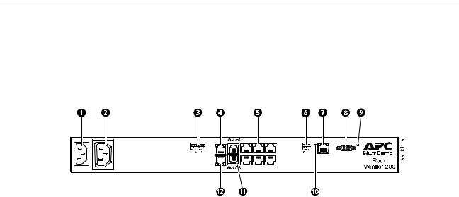
Front
|
Item |
Description |
|
|
|
|
AC Line Inlet |
Provides for the input power connection; see “Specifications” on page 23 for voltage |
|
|
information. |
|
Switched Outlet |
Provides power to a device at a total maximum amperage of 10 A. Activates a connected |
|
|
device when configured events occur. (For example, a fan may be connected to this outlet, |
|
|
and the outlet may be configured to turn on when a high threshold violation occurs for a |
|
|
temperature sensor.) |
|
Voltage Output |
Provides 12 Vdc or 24 Vdc (75 mA) to a connected device. |
|
Relay Output |
Used for connecting relay-controlled external devices. |
|
Peripheral Port |
Not used. |
|
Universal sensor |
Used for connecting APC sensors and third-party dry contact sensors. (See “How to |
|
ports |
Connect Sensors to Universal Sensor Ports” on page 10 for a list of applicable APC |
|
|
sensors.) Third-party dry contact sensors require a NetBotz Dry Contact Cable |
|
|
(NBES0304). |
|
Modbus RS-485 port |
Provides for connection to building management system using the Modbus protocol. |
|
10/100 Base-T |
Provides for connection to the network; status and link LEDs indicate network traffic: |
|
Network Port |
Status LED—blinks orange and green at start-up; indicates the status of the network |
|
|
|
|
|
connection (solid green—IP address established; blinking green—attempting to obtain an |
|
|
IP address). |
|
|
Link LED—blinks to indicate network traffic (green—operating at 10 Mbps; orange— |
|
|
operating at 100 Mbps). |
|
RS-232 Console Port |
Used for connecting the RS-232 configuration cable, when configuring initial network |
|
|
settings. |
|
Reset switch |
Resets the Rack Monitor 200. |
|
Power LED |
Indicates whether the unit is receiving power (green—receiving power; dark—not receiving |
|
|
power). |
4 |
NetBotz Rack Monitor 200 Installation and Quick Configuration Manual |

|
Item |
Description |
|
|
|
|
A-Link ports |
Used to cascade up to twelve NetBotz Rack Sensor Pod 150s (NBPD0150) and a combined |
|
|
total of eight Temperature Sensors with Digital Display (AP9520T) and Temperature/ |
|
|
Humidity Sensors with Digital Display (AP9520TH). Provides communications and power |
|
|
using standard CAT-5 cabling with straight-through wiring. |
|
|
Note: If you cascade ten or more devices, you must connect a supplemental |
|
|
power supply (Power Supply 100-120 Vac/24 Vdc—AP9505i) to a NetBotz |
|
|
Rack Sensor Pod 150. For details, see “How to Cascade Devices to A-Link |
|
|
Ports” on page 12. |
|
Beacon port |
Used for connecting an alarm beacon (AP9324). |
|
|
|
NetBotz Rack Monitor 200 Installation and Quick Configuration Manual |
5 |
How to Install the Rack Monitor 200
Note: Install the Rack Monitor 200 in an environment compatible with the environmental specifications on page 23.
Note: When you install the Rack Monitor 200 in the rack, do not create a hazardous condition due to uneven mechanical loading. For example, do not use the Rack Monitor 200 as a shelf.
You can install the Rack Monitor 200 in the front or the rear of the rack using the rack-mount option, which requires 1 U of rack space. If using an APC NetShelter® VX or SX rack, you also have the option to use the toolless peg-mounts, which do not use any U-spaces.
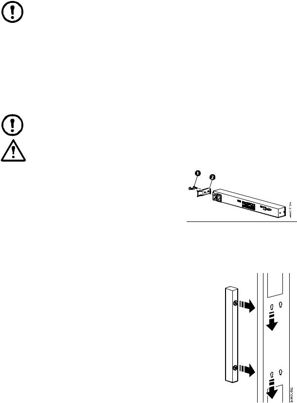
Toolless peg-mount installation
Note: The toolless peg-mount installation is only available with a NetShelter VX or SX rack or enclosure.
Caution: To avoid equipment damage, use only the hardware provided when installing the power cord retainer bracket.
1. Install the power cord retainer bracket as shown.
|
8-32 x 1/4-in Phillips-head screws |
|
|
|
Power cord retainer bracket |
|
|
2. In the left or right cable channel in the rear panel of the enclosure, install the Rack Monitor 200 in a set of mounting holes. Be sure to push down until it locks.
3. See “Power cord and network cable connections” on page 8.
6 |
NetBotz Rack Monitor 200 Installation and Quick Configuration Manual |
Rack-mount installation
1.Choose a location for the Rack Monitor 200 in the front or rear of the rack. The Rack Monitor 200 occupies one U-space. A notched hole or a number on the vertical rail of the rack denotes the middle of a U-space.
Caution: To avoid equipment damage, use only the hardware provided when installing the brackets.
2. Install the brackets ( and ), including the power cord retainer bracket, on the end nearest the AC Line Inlet.
8-32 x 1/4-in Phillips-head screws
Bracket
Power cord retainer bracket
AC Line Inlet
3. Secure the Rack Monitor 200 to the rack, using cage nuts and screws (provided with the rack).
4. See “Power cord and network cable connections” on page 8.
NetBotz Rack Monitor 200 Installation and Quick Configuration Manual |
7 |
Loading...