


MGE™ Galaxy™ PW
20 - 200 kVA
User manual
E-51028230XT/BG - 1
2 - E-51028230XT/BG
Contents
Introduction |
|
General characteristics of MGE™ Galaxy™ PW UPSs ......................................... |
5 |
System description .................................................................................................. |
6 |
Different types of MGE™ Galaxy™ PW systems ................................................... |
7 |
Isolation and protection devices .............................................................................. |
7 |
Operation in on-line mode ....................................................................................... |
8 |
Operation in "eco" mode ......................................................................................... |
10 |
Operation with an engine generator set .................................................................. |
11 |
Inverter shutdown or overload ................................................................................ |
12 |
Output voltage quality and continuity ...................................................................... |
12 |
Description of MGE™ Galaxy™ PW cubicles |
|
UPS cubicle............................................................................................................. |
13 |
Battery cubicle ........................................................................................................ |
14 |
Control panel |
|
General ................................................................................................................... |
14 |
Presentation ............................................................................................................ |
15 |
Start-up |
|
System start-up ....................................................................................................... |
17 |
Start-up of a module ............................................................................................... |
18 |
Shutdown |
|
Shutdown of the inverter ......................................................................................... |
19 |
Shutdown of a rectifier/charger ............................................................................... |
19 |
Control-panel display |
|
General organisation ............................................................................................... |
20 |
Display of messages ............................................................................................... |
20 |
Measurement system .............................................................................................. |
24 |
Voltage measurementsi .......................................................................................... |
24 |
Current measurements ........................................................................................... |
24 |
Power and frequency measurements ..................................................................... |
24 |
Battery measurements ............................................................................................ |
25 |
Selections and settings ........................................................................................... |
25 |
Alarms |
|
General ................................................................................................................... |
28 |
Maintenance bypass ............................................................................................... |
28 |
Environment information |
|
Signal reception ...................................................................................................... |
29 |
Signal transmission ................................................................................................. |
29 |
Logging and time-stamping |
|
Presentation of event time-stamping by MGE™ Galaxy™ PW .............................. |
30 |
Utilisation via the MGE™ Galaxy™ PW display ..................................................... |
30 |
Utilisation via Teleservice ....................................................................................... |
33 |
Maintenance |
|
Maintenance configuration ...................................................................................... |
34 |
Battery maintenance ............................................................................................... |
37 |
Visual check ............................................................................................................ |
37 |
Functional check ..................................................................................................... |
37 |
Training center ........................................................................................................ |
38 |
Options |
|
Isolating and voltage matching transformer for the normal and bypass AC |
|
Source and the load ................................................................................................ |
39 |
Harmonics filter and power factor improvement ..................................................... |
39 |
Safety of life and property ....................................................................................... |
39 |
Empty cubicles ........................................................................................................ |
40 |
Electrical supervision .............................................................................................. |
40 |
E-51028230XT/BG - 3
All products in the MGE™ Galaxy™ PW range are protected by patents. They implement original technology not available to competitors of APC by Schneider Electric.
To take into account evolving standards and technology, equipment may be modified without notice. Indications concerning technical characteristics and dimensions are not binding unless confirmed by APC by Schneider Electric.
This document may be copied only with the written consent of APC by Schneider Electric. Authorised copies must be marked "MGE™ Galaxy™ PW User Manual, N° 51028230XT".
4 - E-51028230XT/BG
Introduction
General characteristics of MGE™ Galaxy™ PW UPSs
UPS power rating in kVA |
|
20 |
|
30 |
|
40 |
50 |
60 |
80 |
100 |
120 |
160 |
200 |
||
Normal AC input |
|
|
|
|
|
|
|
|
|
|
|
|
|
||
number of conductors |
|
3 phases |
|
|
|
|
|
|
|
|
|
|
|||
rated voltage and tolerances |
380 V or 400 V or 415 V ± 10% (adjustable to ± 15%) |
|
|
|
|
||||||||||
rated frequency and tolerances |
50 Hz or 60 Hz / ± 10% |
|
|
|
|
|
|
|
|||||||
THDI with THM filter |
|
< 4% |
|
|
|
|
|
|
|
|
|
|
|
||
power factor with THM filter |
|
up to 0,96 |
|
|
|
|
|
|
|
|
|||||
Bypass AC input |
|
|
|
|
|
|
|
|
|
|
|
|
|
||
number of conductors |
|
3 phases + neutral |
|
|
|
|
|
|
|
|
|||||
rated voltage and tolerances |
380 V or 400 V or 415 V / ± 10% |
|
|
|
|
|
|
||||||||
rated frequency and tolerances |
50 Hz or 60 Hz / ± 10% |
|
|
|
|
|
|
|
|||||||
Load |
|
|
|
|
|
|
|
|
|
|
|
|
|
|
|
number of conductors |
|
3 phases + neutral |
|
|
|
|
|
|
|
|
|||||
Ph/Ph voltages |
|
380 V or 400 V or 415 V (according to setting) |
|
|
|
|
|
||||||||
Ph/N voltages |
|
220 V or 230 V or 240 V (according to setting) |
|
|
|
|
|
||||||||
voltage fluctuations |
|
± 0,5% |
|
|
|
|
|
|
|
|
|
|
|
||
adjustable frequency and tolerances |
|
|
|
|
|
|
|
|
|
|
|
|
|||
(on battery power) |
|
50 Hz or 60 Hz ± 0,05 Hz |
|
|
|
|
|
|
|
||||||
synchronisation with bypass |
± 0,5 Hz (adjustable from ± 0,25 Hz to ± 2 Hz) |
|
|
|
|
|
|||||||||
voltage variation for 0 to 100% load step change |
± 2% ((with battery) |
|
|
|
|
|
|
|
|||||||
permissible overloads |
|
150% for 1 minute, 125% for 10 minutes |
|
|
|
|
|
||||||||
Isc Ph/Ph (% of I rated) |
|
4.2 |
|
2.8 |
|
2.1 |
2.5 |
2.1 |
3.1 |
2.5 |
2.1 |
2.6 |
2.1 |
||
Isc Ph/N (% of I rated) |
|
6.6 |
|
4.4 |
|
3.3 |
4 |
3.3 |
5 |
4 |
3.3 |
4 |
3.3 |
||
THDU Ph/Ph and Ph/N for linear load |
< 1,5% Ph/Ph, < 2% Ph/N |
|
|
|
|
|
|
|
|||||||
THDU Ph/Ph and Ph/N for non-linear load |
< 2% Ph/Ph, < 3% Ph/N |
|
|
|
|
|
|
|
|||||||
(at 80% of Pn) (1) |
|
|
|
|
|
|
|
|
|
|
|
|
|
||
Battery |
|
|
|
|
|
|
|
|
|
|
|
|
|
|
|
|
|
|
|
|
|
|
|
|
|
|
|
|
|||
standard battery type |
|
gas-recombination sealed lead-acid battery |
|
|
|
|
|
||||||||
UPS characteristics |
|
|
|
|
|
|
|
|
|
|
|
|
|
||
|
|
|
|
|
|
|
|
|
|
|
|
|
|
|
|
active power (kW) |
|
16 |
|
24 |
|
32 |
40 |
48 |
64 |
80 |
96 |
128 |
160 |
||
efficiency at 50% load (%) |
|
87.5 |
|
90.5 |
|
91.5 |
92.5 |
93 |
91 |
91.5 |
92 |
93 |
93.2 |
||
(values ± 1%) |
|
|
|
|
|
|
|
|
|
|
|
|
|
||
efficiency at 100% load (%) |
|
91.5 |
|
92 |
|
91.5 |
93 |
92 |
92.5 |
92 |
91.5 |
92.8 |
92.5 |
||
(values ± 1%) |
|
|
|
|
|
|
|
|
|
|
|
|
|
||
heat losses |
(2) |
|
in KW |
1.5 |
|
2.1 |
|
3.4 |
3.6 |
4.7 |
6.2 |
8.1 |
10.1 |
12.2 |
14.8 |
|
|
|
in cal./s |
360 |
|
504 |
|
816 |
864 |
984 |
1488 |
1950 |
2420 |
2930 |
3550 |
storage temperature range |
|
-25 °C to +70 °C |
|
|
|
|
|
|
|
|
|||||
operating temperature range |
0 °C to 35 °C (40 °C for 8 hours) |
|
|
|
|
|
|
||||||||
relative humidity |
|
95% maximum |
|
|
|
|
|
|
|
|
|||||
maximum operating altitude without derating |
< 1000 meters |
|
|
|
|
|
|
|
|
||||||
noise level (dBA) |
|
58 |
|
58 |
|
58 |
60 |
60 |
62 |
64 |
65 |
67 |
68 |
||
dimensions (mm) |
width |
715 |
|
|
|
|
|
|
1015 |
|
|
1215 |
|
||
|
|
|
depth |
825 |
|
|
|
|
|
|
|
|
|
|
|
|
|
|
height |
1400 or 1900 ± 10 |
|
|
|
1900 ± 10 |
|
|
|
||||
weight (kg) (3) |
|
450 |
|
450 |
|
450 |
490 |
490 |
800 |
800 |
800 |
1200 |
1200 |
||
recommended upstream earth-fault protection |
1 A |
|
|
|
|
|
|
|
|
|
|
||||
standards |
design |
|
IEC 146 |
|
|
|
|
|
|
|
|
|
|
||
|
|
product |
|
ENV 50091 |
|
|
|
|
|
|
|
|
|||
|
|
safety |
|
IEC 950, ENV 50091 |
|
|
|
|
|
|
|
||||
|
|
protection |
|
IEC 521 (cubicles 1400 mm high = IP 21, cubicles 1900 mm high = IP 20) |
|
|
|||||||||
|
|
electromagnetic compatibility |
IEC 62040, ENV 50091 |
|
|
|
|
|
|
|
|||||
(1): As per standards ENV 50091-3 / IEC 62040-3.
(2): The losses indicated are those produced at full rated load with the battery float charging. They must be taken into account when sizing the ventilation system.
(3): Not including any built-in options, such as harmonic filters or a bypass AC-source isolation transformer.
E-51028230XT/BG - 5
Introduction (cont.)
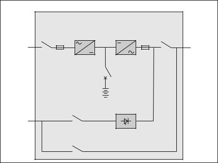
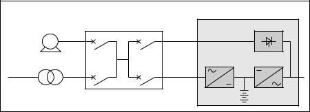
System description
(see figure 1)
a rectifier/charger module (A) converts 3-phase AC power from the normal AC source supply (1) into DC power for the normal inverter input and float charges or recharges the battery;
a battery unit (D) provides backup power for the inverter in the event of a voltage drop or a normal AC source failure;
an inverter module (B) converts the DC power supplied by the rectifier/ charger module or the battery unit into 3-phase AC power for the load;
a static bypass module (C) ensures the instantaneous transfer of the load to the bypass AC source input in the event of an inverter shutdown (initiated by the user or by a protective device) or a sudden overload;
a maintenance bypass isolates the UPS for maintenance and transfers the load to bypass AC source input without interrupting the supply of power. The maintenance bypass is made up of three manual switches (Q3BP, Q4S and Q5N).
Note
the normal AC input and the bypass AC input have different functions and, depending on the installation, may be protected differently upstream and/or come from different sources.
frequency converters are available without backup batteries;
the static bypass line and the maintenance bypass line do not exist in installations where the load frequency and the bypass AC source frequency are different (for example in frequency converters);
when increased power is required, several MGE™ Galaxy™ PW units may be connected in parallel. In this configuration, an "isolation" function is added for the UPS system as a whole for maintenance purposes, without interrupting the supply of power to the load.
The system may also include :
an isolating transformer on bypass AC input;
a passive harmonic filter (FAH) on the normal AC input;
an active harmonic conditioner on the normal AC input;
different remote control, indication and display systems.
Schematic diagram of the MGE™ Galaxy™ PW system
|
|
rectifier/ |
inverter (B): |
|
|
|
|
charger (A): |
DC to AC |
|
|
|
|
AC to DC |
power |
isolation and |
|
|
|
power |
|
||
|
|
|
protection: |
||
|
|
|
|
||
|
(1) |
|
|
FUS |
Q5N |
normal |
|
|
|
load |
|
AC input |
Q1 |
FUE : |
|
|
|
|
|
|
|
||
|
isolation |
|
|
|
|
|
and protection |
QF1: isolation |
|
||
|
|
|
|
||
|
|
|
and protection |
|
|
|
|
|
battery (D): |
|
|
|
|
|
backup power |
|
|
|
|
isolation: |
|
|
|
|
|
Q4S |
static bypass (C): |
|
|
bypass |
(2) |
|
|
|
|
|
|
|
|
|
|
AC input |
|
|
|
|
|
|
|
maintenance bypass: |
|
|
|
|
|
Q3BP |
|
|
|
Fig. 1
6 - E-51028230XT/BG
Introduction (cont.)
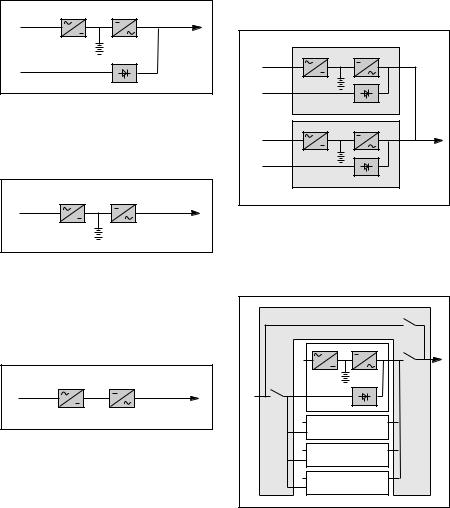
Different types of MGE™ Galaxy™ PW systems
A |
B |
1 |
|
|
D |
|
C |
2 |
|
Fig. 2
Single-UPS unit
A |
B |
1 |
|
|
D |
Fig. 3
Frequency converter without battery backup power
Parallel UPS system
A |
B |
1 |
|
2 |
D |
|
|
|
C |
A |
B |
1 |
|
2 |
D |
|
|
|
C |
Fig. 5
See figure 5 showing two parallelconnected (redundant) UPS units. A static bypass (C) does not exist in
parallel-connected frequency-converter
Frequency converter with |
|
|
Q3BP |
|
battery backup power |
|
|
||
|
|
|
||
|
|
|
1 |
Q5N |
|
|
|
|
|
A |
B |
Q4S |
2 |
|
1 |
|
|
||
|
2 |
|
Galaxy 1 |
|
|
|
|
|
|
|
|
|
1 |
|
Fig. 4 |
|
|
2 |
Galaxy 2 |
|
|
1 |
|
|
|
|
|
2 |
Galaxy 3 |
|
|
|
1 |
|
|
|
|
2 |
Galaxy 4 |
|
|
Fig. 6 |
|
|
configurations.
When increased power is required (two to four parallel units), an external bypass must be added (see figure 6).
Isolation and protection devices
(See figure 1 on previous page):
Q1 (switch):
isolation of the rectifier/charger (A) from the normal AC source (1);
rectifier/charger (A) start-up;
QF1 (circuit breaker):
battery (D) protection and isolation;
Q5N (switch):
isolation of the UPS (B) from the load;
Q4S (switch):
isolation of the static bypass (C) from the bypass AC source (2);
Q3BP (switch):
bypass switch for maintenance;
FUE (fuses):
protection of the rectifier/charger (A) from the normal AC source;
FUS (fuses):
protection of the inverter (B) from the load.
Note:
switch Q3BP does not exist on parallel UPS systems constituted to increase available power;
the "Q3BP" and "Q4S" switches do not exist on frequency converters;
circuit breaker QF1 does not exist on installations without batteries.
External bypass for parallel UPSs and the hot-swap option
See figure 6.
Q5N (switch): isolation of the inverters of all the parallel UPS systems from the load;
Q4S (switch): isolation of the static bypasses (C) on each parallel unit from the bypass AC source (2);
Q3BP (switch): bypass switch for maintenance.
E-51028230XT/BG - 7
Introduction (cont.)
Operation in on-line |
units. |
|
|
|
|
|
|
|
|
|
|
|
||||||||||
Operation with the normal |
||||||||||||||||||||||
mode |
|
|||||||||||||||||||||
|
AC source down |
|
|
|
|
|
|
|||||||||||||||
|
|
|
|
|
|
|
|
|||||||||||||||
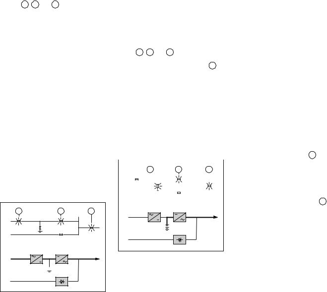
Normal operation |
See figure 8. |
|
|
|
|
|
|
|
|
|
|
|
||||||||||
Normal AC source |
power is available |
In the event of a normal AC source |
||||||||||||||||||||
failure or voltage outside specified |
||||||||||||||||||||||
(see figure 7). |
|
tolerances of ±10% in amplitude (±15% |
||||||||||||||||||||
lights 1 , 4 and |
5 shine green on |
optionally), the rectifier/charger (A) |
||||||||||||||||||||
the control panel; |
|
stops and the battery (D) supplies the |
||||||||||||||||||||
the power necessary for the load is |
necessary backup power to the load via |
|||||||||||||||||||||
provided by the normal AC source (1) |
the inverter (B). The battery, float- |
|||||||||||||||||||||
through the rectifier/charger (A) and the |
connected between the rectifier/charger |
|||||||||||||||||||||
inverter (B); |
|
and the inverter, discharges during this |
||||||||||||||||||||
the rectifier/charger (A) also supplies |
operating mode. |
|
|
|
|
|
|
|
|
|
|
|
||||||||||
the power to float charge and recharge |
Lights 2 , 4 and |
5 shine green. |
|
|
|
|
|
|
||||||||||||||
the battery if any. |
|
The user is warned of battery operation |
||||||||||||||||||||
The rectifier/charger output voltage |
by the slow beeping of the buzzer |
6 |
|
|||||||||||||||||||
(DC) is regulated to supply: |
(see figure 19) and the message |
|
|
|
|
|
|
|||||||||||||||
the float-charging or the recharging |
"LOAD PROTECTED, BATTERY |
|
|
|
|
|
|
|||||||||||||||
voltage for vented lead-acid or Ni/Cd |
DISCHARGING", followed by the |
|
|
|
|
|
|
|||||||||||||||
batteries, |
|
remaining backup time and the percent |
||||||||||||||||||||
a single charge voltage for sealed |
load. |
|
|
|
|
|
|
|
|
|
|
|
||||||||||
lead-acid batteries. |
|
This information is also available via |
||||||||||||||||||||
The voltages depend on the number of |
volt-free changeover contacts for |
|
|
|
|
|
|
|||||||||||||||
remote control devices. |
|
|
|
|
|
|
||||||||||||||||
battery cells and the battery |
|
|
|
|
|
|
||||||||||||||||
|
|
|
|
|
|
|
|
|
|
|
|
|
|
|
|
|
|
|
|
|||
manufacturer. Factory set, they may |
Note: |
|
|
|
|
|
|
|
|
|
|
|
||||||||||
also be adjusted by after-sales support |
In the event of a normal AC source |
|||||||||||||||||||||
technicians. |
|
failure, frequency converters without a |
||||||||||||||||||||
An electronic board continuously |
battery shut down and the load is no |
|||||||||||||||||||||
measures the battery temperature and |
|
|
|
|
|
|
|
|
|
|
|
|
|
|
|
|
|
|
|
|
||
automatically adjusts the voltages. |
|
|
|
|
|
|
|
|
|
|
|
|
|
|
|
|
|
|
|
|
||
2 |
|
|
|
|
4 |
|
|
|
5 |
|
|
|
||||||||||
Note: |
|
|
|
|
|
|
|
|
|
|
|
|||||||||||
In parallel MGE™ Galaxy™ PW |
1 |
|
|
|
|
|
|
|
|
|
|
|
|
|
|
|
|
|
|
|
||
systems, the power drawn by the load |
|
|
|
|
|
|
|
|
|
|
|
|
|
|
|
|
|
|
|
|
||
is equally shared between the different |
2 |
|
|
|
|
|
|
|
|
|
|
|
|
|
|
|
|
|
|
|
||
|
|
|
|
|
|
|
|
|
|
|
|
|
|
|
|
|
|
|
||||
|
|
|
|
|
|
|
|
|
|
|
|
|
|
|
|
|
|
|
|
|
||
1 |
4 |
5 |
A |
B |
1 |
|
|||
1 |
|
|
|
|
|
|
|
|
|
|
|
|
|
D |
2 |
|
|
|
C |
|
|
2 |
|
|
|
|
|
|
AB
1 |
Fig. 8 |
 D
D
C
2
Fig. 7
longer supplied.
Battery time
The available battery time during a normal AC source outage depends on the:
rated capacity of the battery;
power consumed by the load;
temperature of the battery;
age of the battery.
The specified battery time corresponds to a minimum duration at full rated load. The actual backup time can therefore be greater if the system operates below its full rated load during the normal AC source outage. Operation on battery power can be extended beyond the specified time by reducing the load power consumption (by disconnecting non-critical loads).
A "low battery" warning signal is sent via volt-free changeover contacts for remote control devices when the battery voltage reaches a level slightly above the minimum level. This signal warns the user of the imminent end of battery power. On the device itself, the buzzer beeps rapidly.
The message "LOW-BATTERY SHUTDOWN WARNING" is displayed, followed by the remaining backup time and the percent load. Light 2 turns red and flashes.
Battery power stops when the voltage supplied by the battery reaches the minimum threshold (335 V). This results in inverter shutdown and transfer of the load without interruption to the bypass AC source. Light 2 shines red (not flashing). The message "LOAD NOT PROTECTED, ON-LINE MODE" is displayed and the buzzer sounds continuously.
If the bypass AC source also fails, the load is no longer supplied. The inverter automatically shuts down when the time on battery power exceeds three times the specified backup time.
Note:
The "low battery shutdown" warning signal can be sent with an adjustable time delay prior to the effective end of battery power.
8 - E-51028230XT/BG
Introduction (cont.)
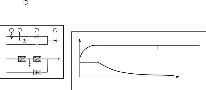
Operation with the normal AC source restored
See figure 9.
When normal AC source power (1) is restored or its voltage returns to within specified tolerances, the system automatically returns to its normal operating mode described above (on the condition it did not reach the end of battery power). If the end of battery power was reached (with the resulting inverter shutdown), the rectifier/charger
(A) restarts automatically, but the inverter (B) must be restarted manually. The rectifier/charger recharges the battery (D) which was discharged during the mains outage. During battery charging, light 2 flashes green.
The message "BATTERY CHARGING" is displayed, together with the value of the recharging current and battery voltage.
1 |
2 |
4 |
5 |
1 |
|
|
|
2 |
|
|
|
|
A |
B |
|
1 |
|
|
|
|
|
D |
|
|
|
C |
|
2 |
|
|
|
Fig. 9
The battery charge cycle takes place in two steps (see figure 10):
step 1: the battery is recharged at a constant current limited to 0.1C10 (i.e. 1/10th of the battery capacity specified for a 10 hour discharge). The DC voltage increases with the battery charge until the charge level is reached;
step 2: the battery is recharged at constant voltage equal to the charge level (maximum value 463 V).
The charging current gradually decreases until reaching a specified low value (floating current).
For vented lead-acid batteries, the rectifier/charger supplies the charging voltage for 0 to 255 hours (parameter defined by the after-sales support department) and then the floating voltage. For sealed lead-acid batteries, the charging and floating voltages are the same.
Note 1:
If the normal AC source failure is shorter than 0 to 255 seconds (default value = 30 seconds) (parameter defined by after-sales support department), the charger automatically supplies the floating voltage given the low battery discharge.
Note 2:
In frequency converters without battery power, the return of normal AC source power results in the automatic restart of the rectifier/charger and the inverter.
Battery charge cycle
U/I |
voltage |
U charge/floating |
|
(sealed batteries) |
|
|
|
U "floating" |
|
|
(vented batteries) |
|
0,1 C10 |
|
|
current |
|
current |
constant voltage |
t |
limiting |
decreasing current |
|
Fig. 10
E-51028230XT/BG - 9

Introduction (cont.)
Operation in "ECO" mode
Normal operation
See figure 11.
The power required by the load is supplied by the bypass AC source (2), via the static bypass (C). The rectifier/ charger (A) supplies the power required to float charge and recharge the battery
(D).
Lights 1 , 3 and 5 shine green and light 4 flashes green. The message "LOAD PROTECTED, ECO MODE" is displayed.
Operation with the bypass AC source outside tolerances
Whatever the status of the normal AC source, operation of the rectifier/ charger (A) with the battery (D) is identical to that presented in the section on on-line mode operation above. When bypass AC source (2) characteristics are outside tolerances (voltage: ±10%; frequency as per personalisation; phase sync with inverter ±3°), the load is supplied via the inverter (B).
From then on, the minimum operating time on the inverter (B) is 2 minutes even if the bypass AC source returns to within specified tolerances. Refer to figure 7 in the general appendix if the normal AC source is present, and to figure 8 if it is absent. After this 2 minute period, the load is immediately transferred to the bypass AC source when the latter returns to within specified tolerances.
Note:
The maximum transfer time of the load from the static bypass (C) to the inverter (B) is 15 ms.
1 |
3 |
4 |
5 |
1 |
|
|
|
2 |
|
|
|
A |
|
B |
|
1 |
|
|
|
|
D |
|
|
|
|
C |
|
2 |
|
|
|
Fig. 11
Operation with bypass AC source restored
no battery discharge (see figure 11). When bypass AC source power supply
(2) is restored or returns to within specified tolerances, the load is transferred back to the static bypass
(C), without an interruption in the supply of power.
Note: this operating mode does not depend on the status of the normal AC source, which may be within or outside the specified tolerances.
after battery discharge (see figure 12).
Operation of the rectifier/charger (A) with the battery (D) is identical to that presented in the section on on-line mode operation above.
1 |
3 |
4 |
5 |
1 |
|
|
|
2 |
|
|
|
A |
|
B |
|
1 |
|
|
|
|
D |
|
|
|
|
C |
|
2 |
|
|
|
Fig. 12
Forced transfer and return transfer
forced transfer. When the load is supplied via the static bypass (C), it may be transferred to the inverter (B) by pressing pushbutton 20 (see figure 19 in the "control panel" section). The message "FORCED TRANSFER
TO INVERTER REQUESTED, POWER TO LOAD MAY BE INTERRUPTED" is displayed. Confirmation by pressing pushbutton 12 is required to effectively force transfer. The message "LOAD FORCED TO INVERTER, ECO MODE" is displayed. Whatever the status of the bypass AC source, a return to normal operation in "ECO" mode is possible only through a forced return transfer to the static bypass (C).
forced disconnection: as the load is supplied by the inverter (B), it can be transferred to the bypass AC source (M2) via the static bypass (C) by pressing the pushbutton 20 . The message "FORCED TRANSFER TO M2 REQUESTED, POWER TO LOAD MAY BE INTERRUPTED" is then displayed. Confirmation by pressing pushbutton 12 is required for disconnection.
Note:
There are two possibilities: the bypass AC source is within tolerances or outside tolerances. In the first case, the UPS in "ECO" mode returns to normal operation.
In the second case, the transfer will take place with a power cut to the load if the bypass AC source is present, or the load will cease to be supplied if it is absent. In both cases, the display reads "LOAD NOT PROTECTED, ECO MODE".
Caution:
Return to normal operation of the installation in the "ECO" mode is possible only after the bypass AC source has returned to within specified tolerances.
10 - E-51028230XT/BG
Introduction (cont.)
Inverter shutdown or overload
See figure 13 for devices or installations operating in on-line mode with a bypass AC source.
3 |
5 |
1 |
|
2 |
|
A |
B |
1 |
|
D |
|
|
C |
2 |
|
Fig. 13
If the conditions are not satisfied, the inverter will current limit to 165% of its rated current for 1 second before stopping;
in the event of a small but extended overload (i.e. a continuous level of power exceeding the full rated load), the inverter will continue to supply power for a period depending on the magnitude of the overload (10 minutes for a 125% overload, 1 minute for a 150% overload). See the overload curve in figure 14;
in all three of the above cases, inverter shutdown and supply of the load via the bypass AC source results in the following on the control panel:
|
light |
4 goes off, |
|
activation of the buzzer (continuous |
|
beep), |
3 shines green, |
|
|
light |
|
|
the message "LOAD NOT |
|
PROTECTED, ON-LINE MODE" is displayed.
Parallel UPSs with redundancy
the shutdown of one UPS unit is of no consequence for the load. The others each take up an equal amount of load power and the load continues to be supplied normally;
Unit shutdown results in the following on the control panel:
lights 4 and 5 go off,
activation of the buzzer (continuous beep),
the message "LOAD NOT PROTECTED, PARALLEL ON-LINE MODE" is displayed;
in the event of an overload, the system only loses its redundancy as long as the overload is less than the total rated power of the functioning units. If the overload is greater, the operating mode is that previously described for systems without redundancy.
Single-UPS unit (on-line or "ECO" mode)
in the event of a UPS shutdown (initiated by the user or by an internal protective device), the load is automatically transferred to the bypass AC source. If transfer conditions are satisfied, transfer takes place instantly, without interruption to the load;
Note: transfer conditions are not satisfied when bypass AC source characteristics are outside tolerances (voltage: ±10%; frequency as per personalisation; phase sync with inverter ±3°);
in the event of a major transient overload (greater than 1.65 In), immediate transfer takes place as above, without interruption to the load. The return to the inverter is automatic when the overload disappears if the number of possible returns has not been reached (0 to 255, programmable by personalisation). If this number has been reached, the load continues to be supplied by the bypass AC source. This operating mode allows start-up of load devices causing high inrush currents. This system requires satisfied transfer conditions.
Parallel UPSs without redundancy
The shutdown of one inverter results in overload on the other inverters in operation. Two cases may then arise:
if the overload on each remaining inverter is > than 1.65 ln, the load is immediately transferred to the bypass AC source;
if the overload is less than 1.65 ln, the remaining inverters support the overload (see curve in figure 14), and the load is transferred to the bypass AC source;
after this transfer:
|
the light 4 |
goes off, |
|
the buzzer is activated and sounds |
|
continuously, |
|
|
|
the light 3 |
goes on and turns green, |
|
the message "LOAD NOT |
|
PROTECTED, PARALLEL ON-LINE MODE" is displayed.
Frequency converters
in the event of a shutdown, the load is no longer supplied with power;
in the event of a major transient overload (greater than 1.65 In), the inverter will current limit to 165% of their rated current for 1 second before stopping;
in the event of a smaller but prolonged overload, the inverter respects the same overload curve as the single inverter and shuts down;
in all three of the above cases, inverter shutdown results in the following:
lights 4 and 5 go off,
activation of the buzzer (continuous beep),
the message "LOAD NOT PROTECTED, ON-LINE MODE" is displayed.
|
I |
|
|
|
|
|
|
|
|
|
|
|
|
1,5 |
In |
|
|
|
|
|
|
|
|
|
|
|
|
1,35 |
In |
|
|
|
|
|
|
|
|
|
|
|
|
1,25 |
In |
|
|
|
|
|
|
|
|
|
|
|
|
1,15 |
In |
|
|
|
|
|
|
|
|
|
|
|
|
1,10 |
In |
|
|
|
|
|
|
|
|
|
|
|
|
1,05 |
In |
|
|
|
|
|
|
|
|
|
|
|
|
|
In |
|
|
|
|
|
|
|
|
|
|
|
|
|
1 |
2 |
3 |
4 |
5 |
6 |
7 |
8 |
9 |
10 |
30 |
120 |
t (min) |
Fig. 14
E-51028230XT/BG - 11
Introduction (cont.)
Operation with an engine generator set
See figure 15 below.
If a stand-by generator is included in the installation, it is generally started automatically in the event of a normal AC source failure and connected to the main low voltage switchboard. It is disconnected when normal AC source power is restored.
With such a system, the required battery time may be reduced to the time necessary for starting and bringing on line the stand-by generator. The battery
(D) supplies power to the inverter (B) during the transfers:
normal AC source to the generator;
generator to the normal AC source. The transfer sequences described above (normal AC source battery, battery generator, generator battery, and battery normal AC source) are fully automatic. They in no way affect the load and require no manual operation by the user.
Note:
To avoid load surges on the generator, the rectifier/charger is started with a 10 second maximum current consumption walk-in (lasting 3 to 10 seconds, depending on the percent load).
To avoid overloading an undersized engine generator set, it is possible to set a maximum power level drawn by the normal AC input. Any additional power required is supplied by the battery. This modification can be made on site by an APC by Schneider Electric technician.
Output voltage quality and continuity
The output voltage is stable in amplitude and frequency and is free of interruptions or transients outside specified tolerances, irrespective of normal AC source or load disturbances (outages, load step changes, etc.).
Steady state voltage regulation
For stable or slowly varying load conditions, the inverter output voltage is regulated to within ±0.5% in amplitude. The frequency of the output voltage can theoretically be regulated to within 0.1% of the rated value, however the output frequency range may be intentionally extended to a maximum of ±2 Hz so that the inverter can remain synchronised with the bypass AC source and its inherent frequency fluctuations, thus enabling transfer of the load to the bypass line at any time.
Note:
The output frequency range can be personalised and if necessary modified on the customer site by a qualified APC by Schneider Electric support technician from ±0.25 Hz to ±2 Hz in 0.25 HZ steps.
When the bypass AC source voltage moves outside this frequency range, the inverter is desynchronised and operates in "free running" mode, with the output frequency regulated to a high level of accuracy by a quartz oscillator.
When the bypass AC source frequency returns to within the specified tolerances, the inverter is gradually resynchronised to the bypass line at a rate of 0.5 Hz to 2 Hz/s (as per the value personalised by the after-sales support department), thus avoiding exposing the load to sudden frequency variations.
Transient voltage regulation
The inverter output voltage is not notably affected by instantaneous major variations in load characteristics. This is made possible by the PWM (Pulse Width Modulation) chopping technique and the microprocessorbased regulation system that instantly compensates for any variation. In particular, the inverter output voltage remains within +/- 2% of the rated voltage for load step changes of 0 to 100% or of 100 to 0%.
Example of an installation with an engine generator set
|
MGE™ Galaxy™ PW |
|
generator |
main LV switchboard |
C |
G |
Mains 2 |
|
|
|
|
|
A |
B |
HV system |
Mains 1 |
D
Fig. 15
12 - E-51028230XT/BG
 Loading...