


MGETM GalaxyTM 9000
50, 60 Hz
800 - 900 kVA
User manual
Single-unit UPS
Modular UPS
Parallel UPS with SSC
Frequency converter
Static Switch Cubicle
34006452EN/AC - Page 2
|
|
Contents |
1. Introduction |
|
|
1.1 |
System performance ................................................................................................................... |
5 |
1.2 |
System description ...................................................................................................................... |
5 |
1.3 |
Different types of MGETM GalaxyTM 9000 systems ................................................................. |
6 |
1.4 |
Isolation and protection devices ................................................................................................. |
8 |
|
UPS or converter cubicles (figure 8) ............................................................................................................... |
8 |
|
Static Switch Cubicle (figure 9) ....................................................................................................................... |
8 |
|
External maintenance bypass cubicle (figure 10) ............................................................................................ |
9 |
1.5 |
Main operating modes .................................................................................................................. |
9 |
|
Normal operation ............................................................................................................................................. |
9 |
|
Operation with Mains 1 down (figure 12) ....................................................................................................... |
10 |
|
Battery time .................................................................................................................................................... |
10 |
|
Operation with Mains 1 restored (figure 13) .................................................................................................. |
11 |
|
Installation with an engine generator set (figure 15) ................................................................................... |
12 |
|
Output voltage quality and continuity ............................................................................................................. |
13 |
2. Description of MGETM GalaxyTM 9000 cubicles |
|
|
2.1 |
Inverter cubicle .......................................................................................................................... |
14 |
2.2 |
Static Switch Cubicle ................................................................................................................ |
15 |
2.3 |
External maintenance bypass cubicle .................................................................................... |
15 |
3. Control panel |
|
|
3.1 |
Visible control panel .................................................................................................................. |
17 |
3.2 |
Hidden control panel ................................................................................................................. |
20 |
4. Start-up |
|
|
4.1 |
System start-up ........................................................................................................................... |
23 |
|
Single-unit or modular UPS ........................................................................................................................... |
23 |
|
Multi-bypass modular UPS ............................................................................................................................ |
24 |
|
Modular UPS with external maintenance bypass .......................................................................................... |
25 |
|
Frequency converters .................................................................................................................................... |
26 |
|
Parallel UPS systems with a Static Switch Cubicle ........................................................................................ |
27 |
4.2 |
Start-up of a unit ......................................................................................................................... |
27 |
|
Start-up of a rectifier/charger ......................................................................................................................... |
27 |
|
Start-up of an inverter .................................................................................................................................... |
27 |
5. Shutdown |
|
|
5.1 |
Shutdown of a unit ...................................................................................................................... |
28 |
|
Shutdown of an inverter ................................................................................................................................. |
28 |
|
Shutdown of an rectifier/charger .................................................................................................................... |
29 |
5.2 System shutdown ....................................................................................................................... |
29 |
|
|
Single-unit or single modular UPS ................................................................................................................. |
29 |
|
Modular UPS with external maintenance bypass .......................................................................................... |
30 |
|
Multi-bypass modular UPS ............................................................................................................................. |
30 |
|
Frequency converters (no Mains 2) .............................................................................................................. |
30 |
|
Parallel UPSs with SSC (with Mains 2) .......................................................................................................... |
31 |
5.3 |
Buzzer reset ................................................................................................................................ |
31 |
6. Alarms |
|
|
6.1 |
Maintenance bypass .................................................................................................................. |
32 |
7. Environment information |
|
|
7.1 |
Standard information Media Contacts 9 .................................................................................. |
33 |
|
Signal reception ............................................................................................................................................. |
33 |
|
Signal transmission ........................................................................................................................................ |
33 |
|
|
34006452EN/AC - Page 3 |
Contents
7.2 "LED" signalling box (optional) .................................................................................................. |
34 |
7.3 Additional information "Media Contacts 15" .......................................................................... |
34 |
Signal reception ............................................................................................................................................. |
35 |
Signal transmission ....................................................................................................................................... |
35 |
8. Maintenance
8.1 |
Maintenance configuration ......................................................................................................... |
36 |
|
Single-unit or single modular UPS (figure 25) .............................................................................................. |
36 |
|
Multi-bypass modular UPS (figure 26) ......................................................................................................... |
36 |
|
Modular UPS with external maintenance bypass (figure 27) ........................................................................ |
37 |
|
Frequency converter or parallel UPS with SSC (figure 28) ............................................................................ |
38 |
|
Static Switch Cubicle (figure 29) ..................................................................................................................... |
38 |
8.2 |
Battery maintenance .................................................................................................................. |
39 |
8.3 |
Autodiagnostics .......................................................................................................................... |
39 |
8.4 |
Visual check ................................................................................................................................ |
39 |
8.5 |
Functional check ........................................................................................................................ |
39 |
8.6 |
Training centres ........................................................................................................................... |
40 |
9. "Monitor" alphanumeric display
9.1 |
General ........................................................................................................................................ |
41 |
|
Display ........................................................................................................................................................... |
41 |
9.2 |
Control panel ............................................................................................................................... |
42 |
9.3 |
Lights 1 to 8 ................................................................................................................................. |
43 |
9.4 |
Alarm display and buzzer reset ................................................................................................. |
44 |
|
List of general alarms .................................................................................................................................... |
44 |
|
List of secondary alarms ............................................................................................................................... |
45 |
9.5 |
Measurement system ................................................................................................................. |
50 |
9.6 |
Voltage measurements ............................................................................................................... |
51 |
9.7 |
Current measurements .............................................................................................................. |
52 |
9.8 Frequency and power measurements ...................................................................................... |
53 |
|
9.9 |
Battery measurements ............................................................................................................... |
54 |
9.10 Inverter On/Off commands ...................................................................................................... |
56 |
|
9.11 Language, display contrast and buzzer volume settings ..................................................... |
57 |
|
9.12 Display system configuration .................................................................................................. |
58 |
|
10. Options
10.1 |
"LED" signalling box ................................................................................................................ |
59 |
10.2 |
"Tele-Monitor" remote indications unit .................................................................................. |
59 |
10.3 |
"GTC link" communications system ....................................................................................... |
59 |
10.4 |
"Vision" display ........................................................................................................................ |
60 |
10.5 |
"Remote vision" display .......................................................................................................... |
60 |
10.6 |
Insulating and Mains 1, Mains 2 and load voltage matching transformer ........................... |
60 |
10.7 |
Double bridge rectifier-charger ............................................................................................... |
61 |
10.8 |
Battery "Temperature Monitor" ............................................................................................... |
61 |
10.9 |
Empty cubicles ........................................................................................................................ |
61 |
34006452EN/AC - Page 4
1. Introduction
1.1 System performance
A MGETM GalaxyTM 9000 uninterruptible power supply (UPS) delivers 3-phase power with the following characteristics:
–stable voltage (±0.5 % under steady state conditions and +/-5% under transient conditions for load step changes of 25 to 100 % or of 100 to 25 %);
–stable frequency (±0.05Hz without Mains 2);
–or frequency synchronized with Mains 2 to 50/60 Hz ±2 Hz (value may be configured in 0.25 Hz steps);
–free of micro-breaks and outages for the duration of the battery time (10, 15 or 30 minutes);
–less than 4 % distortion in all system configurations with linear loads;
–less than 5 % distortion for a 100 % non-linear load with a peak factor of up to 3.5.
The acoustic noise level of a MGETM GalaxyTM 9000 UPS is under 75 dBA.
Single-line diagram of the MGETM GalaxyTM 9000 system
|
|
|
|
|
|
|
|
|
|
|
|
|
|
|
|
|
|
|
|
|
|
|
|
|
|
|
|
|
|
|
|
|
|
|
|
|
|
|
B |
|
|
|
|
|
|
|
|
|
|
|
|
|
|
|
|
|
|
|
|
|
|
|
|
|
maintenance |
|
|
|
|
|
|
|
|
|
|
|
|
|
|
|
|
|
bypass |
|
|
|
|
|
|
mains 2 |
|
|
|
|
|
|
|
|
|
|
|
|
|
isolation |
|
|
|
|
|
|
|
|
|
|
|
|
|
|
|
|
|
|
|
||
(bypass input) |
|
|
|
isolation |
|
|
|
|
emergency |
|
and |
|
|
load |
|||
|
|
|
|
|
|
|
|
|
|
|
|
||||||
|
|
|
|
|
|
|
|
|
|
protection |
|
|
|||||
|
|
|
|
|
|
|
|
|
bypass |
|
|
|
|||||
|
|
|
|
|
|
|
|
|
|
|
|
|
|
|
|
||
|
|
|
|
|
|
|
|
|
|
|
|
|
|
|
|
|
|
|
|
|
|
|
|
|
|
|
|
|
|
|
|
|
|
|
|
|
|
|
|
|
|
|
|
|
|
|
|
|
|
|
|
|
|
|
|
|
|
|
|
|
|
|
|
|
|
|
|
|
|
||
mains 1 |
|
isolation |
AC/DC |
|
|
DC/AC |
|
|
|
|
|
||||||
|
and |
conversion |
|
|
conversion |
|
|
|
|
|
|||||||
(normal input) |
|
protection |
|
|
|
|
|
|
|
|
|
|
|
|
|||
|
|
|
|
|
|
|
|
|
|
|
|
|
|
|
|||
|
|
|
|
|
|
|
|
isolation and |
|
|
|
|
|
|
|||
|
|
|
|
|
|
|
|
protection |
|
|
|
|
|
|
|||
|
|
|
|
|
|
|
|
|
|
|
|
|
|
|
|
||
|
|
|
|
|
|
|
|
|
|
|
|
|
|
|
|||
|
|
|
|
|
|
|
|
|
battery |
|
|
|
|
|
|
||
|
|
|
A |
|
|
|
|
|
|
|
|
|
|
|
|
|
|
|
|
|
|
|
|
|
|
|
|
|
|
|
|
|
|||
|
|
|
|
|
|
|
|
|
|
|
|
|
|
|
|
|
|
|
|
|
|
|
|
|
|
|
|
|
|
|
|
|
|
|
|
1.2System description
–a rectifier-charger (RC) module converts 3-phase AC power from the Mains 1 supply into DC power for the normal inverter input and float charges or recharges the batteries;
–a battery unit provides backup power for the inverter in the event of a voltage drop or a Mains 1 failure;
–an inverter module converts the DC power supplied by the rectifier-charger module or the battery unit into 3-phase AC power for the load;
–an emergency bypass module ensures the instantaneous transfer of the load via the static switch to the Mains 2 bypass line in the event of an inverter shutdown (initiated by the user or by a protective device) or a sudden overload;
–a maintenance bypass which isolates the UPS for maintenance and transfers the load without interrupting the supply of power. The maintenance bypass is made up of three manual switches.
Note:
–the Mains 1 normal input and the Mains 2 bypass input have different functions and, depending on the installation, may be protected differently upstream and/or come from different sources;
–frequency converters are available without backup batteries;
–the emergency bypass line and the maintenance bypass line do not exist in installations where the load frequency and the Mains 2 frequency are different (for example in frequency converters);
–for reasons of redundancy and/or increased power, the rectifier-charger, inverter and battery modules (the UPS, part A in the MGETM GalaxyTM 9000 schematic diagram above) may be arranged in parallel lines. In this case, an isolation function is added to the output of each UPS for maintenance without disrupting the load.
In this type of system, the components of part B in the diagram are located in a separate cubicle referred to as the "Static Switch Cubicle".
The system may also include:
–an isolating transformer on the Mains 2 line;
–a harmonics filter on the Mains 1 input;
–different remote control, indication and display systems;
–a double bridge rectifier-charger module.
34006452EN/AC - Page 5
Introduction
1.3Different types of MGETM GalaxyTM 9000 systems
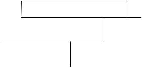
–Single-unit or modular UPS: (figure 1)
Q3BP |
static switch |
mains 2 |
|
rectifier- |
inverter |
charger |
|
mains 1 |
load |
|
battery |
Fig. 1
– Multi-bypass modular UPSs: (figure 2)
Note:
2 modular UPSs (identical ratings) can be parallel-connected in this way.
|
|
|
|
|
|
|
|
|
|
|
|
|
|
|
|
|
|
|
|
|
|
Q3BP |
static switch |
|
|
|
|||||||
|
|
|
|
|
|
|
|
|
|
|
|
|
|
|
|
|
|
|
|
|
|
|
|
|
|
|
|
|
|
|
|
|
|
|
|
mains 2 |
|
|
rectifier- |
|
|
|
|
|
|
|
|
|
|
|
|
|
|
|
|
|
|
|
|
|
|
|
|
|
|
||
|
|
|
|
|
|
inverter |
|
|
|
|
||||||
|
|
|
|
|
charger |
|
|
|
|
|
||||||
|
|
mains 1 |
|
|
|
|
|
|
|
|
|
|
|
|
|
|
|
|
|
|
|
|
|
|
|
|
|
|
|
|
|
|
|
|
|
|
|
|
|
|
|
|
|
|
|
|
|
|
|
|
|
|
|
|
|
|
|
battery |
|
|
load |
||||||
|
|
|
|
|
|
|
|
|
|
|
|
|
|
|
|
|
|
|
|
|
|
|
|
|
|
|
|
|
|
|
|
|
|
|
|
|
|
|
Q3BP |
static switch |
|
|
||||||||
|
|
|
|
|
|
|
||||||||||
|
|
|
|
|
|
|
|
|||||||||
|
|
|
|
|
|
|
|
|
|
|
|
|
|
|
|
|
|
|
|
|
|
|
|
|
|
|
|
|
|
|
|
|
|
|
|
mains 2 |
|
|
rectifier- |
|
|
|
|
|
|
|
|
|
|
|
|
|
|
|
|
|
|
|
|
|
|
|
|
|
|
||
|
|
|
|
|
|
inverter |
|
|
|
|
||||||
|
|
|
|
|
charger |
|
|
|
|
|
||||||
|
|
mains 1 |
|
|
|
|
|
|
|
|
|
|
|
|
|
|
|
|
|
|
|
|
|
|
|
|
|
|
|
||||
|
|
|
|
|
|
|
|
|
|
|
|
|
||||
|
|
|
|
|
|
|
battery |
|
|
|
||||||
|
|
|
|
|
|
|
|
|
|
|
|
|
|
|
|
|
Fig. 2
– Modular UPSs with external maintenance bypass: (figure 3)
Note:
Up to 4 UPS (identical ratings) can be parallel-connected.
|
|
|
|
Q3BP |
|
|
|
||||||
|
|
|
|
|
|
|
|
|
|
|
|
|
|
|
|
|
|
static switch |
|
|
|
||||||
mains 2 |
|
|
|
|
|
|
|
|
|
|
|
|
|
|
|
|
|
|
|
|
|
|
|
|
|
|
|
|
|
rectifier- |
|
|
|
|
|
|
|
|
|
|
|
|
|
|
|
|
|
|
|
|
|
|
|
||
|
|
|
inverter |
|
|
|
|
||||||
|
|
charger |
|
|
|
|
|
||||||
mains 1 |
|
|
|
|
|
|
|
|
|
|
|
|
|
|
|
|
|
|
|
|
|
|
|
|
|
|
|
|
|
|
|
|
|
|
|
|
|
|
|
|
|
|
|
|
|
battery |
|
|
load |
||||||
|
|
|
|
|
|
|
|
|
|
|
|
|
|
|
|
|
|
|
|
|
|
|
|
|
|
|
|
|
|
|
|
static switch |
|
|
|
||||||
mains 2 |
|
|
|
|
Q5N |
||||||||
|
|
|
|
|
|
|
|
|
|
|
|||
|
|
|
|
|
|
|
|
|
|
|
|
|
|
|
|
rectifier- |
|
|
|
|
|
|
|
|
|
|
|
|
|
|
|
|
|
|
|
|
|
|
|
||
|
|
|
inverter |
|
|
|
|
||||||
|
|
charger |
|
|
|
|
|
||||||
mains 1 |
|
|
|
|
|
|
|
|
|
|
|
|
|
|
|
|
|
|
|
|
|
|
|
||||
|
|
|
|
|
|
|
|
|
|
|
|
|
|
|
|
|
|
battery |
|
|
|
||||||
|
|
|
|
|
|
|
|
|
|
|
|
|
|
|
|
|
|
|
|
|
|
|
|
|
|
|
|
Fig. 3
34006452EN/AC - Page 6
Introduction
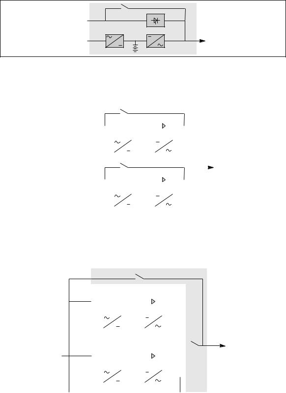
– Frequency converter with battery backup power: (figure 4)
rectifier- |
inverter |
charger |
|
mains 1 |
load |
|
battery |
Fig. 4
– Frequency converter without backup power: (figure 5)
rectifier- |
inverter |
charger |
|
mains 1 |
load |
Fig. 5
– Frequency converters with backup power: (figure 6)
rectifier- |
inverter |
charger |
|
|
battery |
rectifier- |
inverter |
charger |
|
mains 1 |
load |
|
battery |
rectifier- |
inverter |
charger |
|
|
battery |
Fig. 6
– Parallel UPSs with SSC: (figure 7)
Note:
Up to 6 UPS (identical ratings) can be parallel-connected in this way.
|
|
|
|
Q3BP |
|
|
|
|
|
|
|
||
mains 2 |
|
|
|
|
|
|
|
|
|
|
|
||
|
|
|
Static Switch Cubicle |
|
|
|
|
|
|
|
|||
|
|
|
|
|
|
|
|
|
|
|
|
|
|
|
|
|
|
|
|
|
|
|
|
|
|
|
|
|
|
|
|
rectifier- |
|
inverter |
|
|
|
||||
|
|
|
|
charger |
|
|
|
|
|||||
|
|
|
|
|
|
|
|
|
|
|
|
|
|
|
|
|
|
|
|
|
|
|
|
|
|
|
|
|
|
|
|
|
|
|
|
|
|
|
|
|
|
|
|
|
|
|
|
|
battery |
|
|
|
|||
mains 1 |
|
|
|
|
|
|
|
|
|
|
|
|
load |
|
|
|
rectifier- |
|
inverter |
|
|
||||||
|
|
|
|
|
|
||||||||
|
|
|
|
charger |
|
|
|
|
|||||
|
|
|
|
|
|
|
|
|
|
|
|
|
|
|
|
|
|
|
|
|
|
|
|
|
|
|
|
|
|
|
|
|
|
|
|
|
|
|
|
|
|
battery
Fig. 7
34006452EN/AC - Page 7
Introduction
1.4 Isolation and protection devices
UPS or converter cubicles (figure 8)
–Q1 (switch): isolation from Mains , RC start-up;
–QF1 (circuit breaker):
battery protection and isolation;
–Q5N (switch):
isolation of the inverter, frequency converter or static switch module from the load;
–Q4S (switch):
isolation of the static switch from Mains 2;
–Q3BP (switch):
bypass switch for maintenance;
–FU1-2-3 (fuses):
protection of the RC from Mains 1;
–FU5-6-7 (fuses):
protection of the inverter from the load.
Note:
–switches Q4S and Q3BP do not exist on frequency converters,
–circuit breaker QF1 does not exist on frequency converters without a battery.
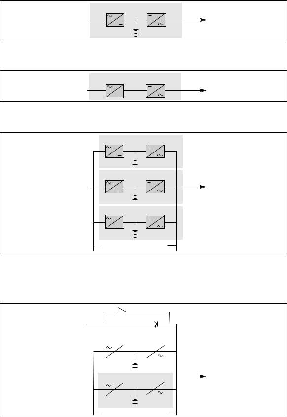
Example of a single-unit UPS or single modular UPS
Q3BP
|
|
|
|
|
Q4S |
static switch |
||||||||
mains 2 |
|
|
|
|
|
|
||||||||
|
|
|
|
|
|
|||||||||
|
|
|
|
|
|
|
|
|
|
|||||
|
|
|
rectifier- |
|
|
|
|
|
|
|
|
|
|
|
|
|
|
|
|
|
|
|
inverter |
||||||
Q1 |
charger |
|
|
|
|
|
||||||||
|
|
|
|
|
|
|
|
|
|
|
Q5N |
|||
|
|
|
|
|
|
|
|
|
|
|
||||
mains 1 |
|
|
|
|
|
|
|
|
|
|
|
|
|
load |
|
|
|
|
|
|
|
|
|
|
|
|
|
||
FU1-2-3 |
|
|
QF1 |
|
|
|
FU5-6-7 |
|||||||
|
|
|
|
|
||||||||||
|
|
|
|
|
|
|
|
|
|
|
||||
|
|
|
|
|
|
|
|
|
battery |
|||||
|
|
|
|
|
|
|
|
|
||||||
|
|
|
|
|
|
|
|
|
||||||
|
|
|
|
|
|
|
|
|
||||||
|
|
|
|
|
|
|
|
|
|
|
|
|
|
|
|
|
|
|
|
|
|
|
|
|
|
|
|
|
|
Fig. 8
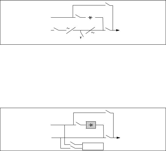
Static Switch Cubicle (figure 9)
–Q4S (switch) :
isolation of the static switch (and mechanical contactor K2S) from Mains 2;
–Q3BP (switch) :
bypass switch for maintenance;
–Q5N (switch) :
isolation of the load from the parallel UPSs;
–Q1 (fuse switch) :
protection of the cubicle control electronics from the parallel-connected inverter outputs;
–Q2 (fuse switch) :
protection of the cubicle control electronics from Mains 2.
|
Q3BP |
|
static switch |
mains 2 |
Q4S |
|
|
parallel |
Q5N |
load |
|
UPSs |
|
Q2 |
|
Q1 |
control |
|
electronics |
Fig. 9
34006452EN/AC - Page 8
Introduction
External maintenance bypass cubicle (figure 10)
–Q3BP (switch) :
bypass switch for maintenance;
–Q5N (switch) :
isolation of the load from the parallel-connected UPSs.
maintenance |
|
Q3BP |
|
|
|
bypass line |
|
|
parallel |
|
Q5N |
|
load |
|
|
||
modular UPSs |
|
|
|
|
|
Fig. 10
1.5 Main operating modes
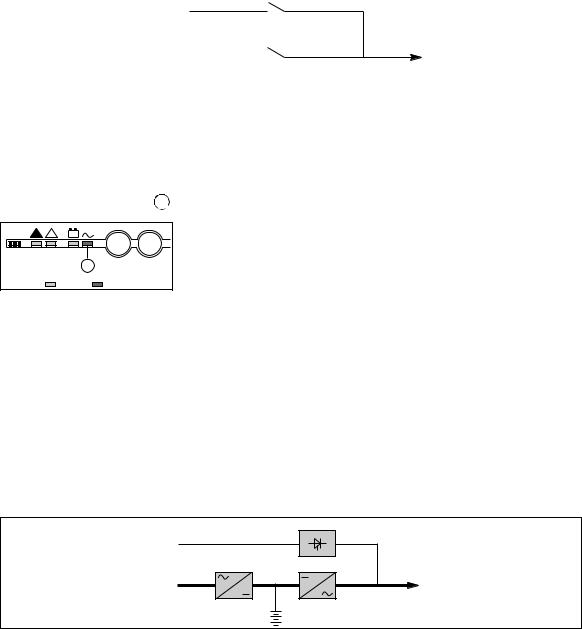
Normal operation
Mains 1 power is available: (see figure 11).
The green "load protected" light 5  on the control panel is on.
! |
! |
légend :
+ –
5
off on
IO
The power necessary for the load is provided by Mains 1 through the rectifier-charger and the inverter. The rectifier-charger also supplies the power to float charge and recharge the battery (1).
The rectifier-charger output voltage (DC) is regulated for the different battery types and charging modes:
–vented lead-acid or Ni/Cd batteries: two different voltages, one for float charging and one for recharging;
–sealed lead-acid batteries: a single voltage for both charge functions.
The voltages depend on the number of battery cells and the battery manufacturer. They can be factory set and are adjustable by the after-sales support technicians.
An optional electronic board may be used to continuously measure the battery temperature and automatically adjust the voltages.
Parallel UPS systems:
the power drawn by the load is equally shared between the different UPSs.
(1) Except for frequency converters without a battery
|
static switch |
mains 2 |
|
rectifier- |
inverter |
charger |
|
mains 1 |
load |
|
battery |
Fig. 11
34006452EN/AC - Page 9
Introduction
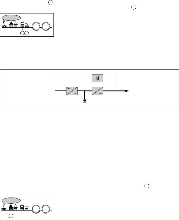
Operation with Mains 1 down (figure 12)
In the event of a Mains 1 failure or Mains 1 voltage outside specified tolerance of –10 % in amplitude (–15 % optionally), the rectifier-charger stops and the battery supplies the necessary backup power to the load via the inverter. The battery, floatconnected between the rectifier-charger and the inverter, discharges during this operating mode.
The green "load protected" light 5 on the control panel is on.
The user is warned of battery operation by a buzzer and the orange "load on battery" light 4 on the control panel.
beep...beep...
!!
+ –
IO
45
This information is also available via volt-free changeover contacts for remote control devices.
In this case, there is a 30 seconds delay.
Note:
In the event of a Mains 1 failure, frequency converters without a battery shut down and the load is no longer supplied.
|
static switch |
mains 2 |
|
rectifier- |
inverter |
charger |
|
mains 1 |
load |
|
battery |
Fig. 12
Battery time
The available battery time during a Mains 1 outage depends on the:
–rated capacity of the battery;
–power consumed by the load;
–temperature of the battery;
–age of the battery.
The specified battery time corresponds to a minimum duration at full rated load.
The actual backup time can therefore be greater if the system operates below its full rated load during the Mains 1 outage. Operation on battery power can be extended beyond the specified time by reducing the load power consumption
(by disconnecting non-critical loads).
A "low battery shutdown" warning signal is sent via volt-free changeover contacts for remote control devices when the battery voltage reaches a level slightly above the minimum level. This signal warns the user of the imminent end of battery power. On the device itself, the buzzer beeps increasingly rapidly and loudly.
Battery power stops when the voltage supplied by the battery reaches the voltage minimum (340 V). This results in inverter shutdown and transfer of the load without interruption to Mains 2. The red "load not protected" light 2  on the control panel is on.
beep...beep...
!!
+ –
IO
2
If Mains 2 also fails, the load is no longer supplied. Normally, the inverter shuts down when the time on the battery power exceeds three times the specified backup time.
Note:
As an optional function (battery time estimator), the "low battery shutdown" warning signal can be sent with an adjustable time delay prior to the effective end of battery power.
34006452EN/AC - Page 10
Introduction
Operation with Mains 1 restored (figure 13)
When Mains 1 power is restored or its voltage returns to within specified tolerances, the system automatically returns to its normal operating mode described above (on the condition it did not reach the end of battery power).
If the end of battery power was reached (with the resulting inverter shutdown), the RC restarts automatically, but the inverter must be restarted manually, either locally or remotely in systems equipped with a remote-control unit.
The rectifier-charger recharges the battery which was discharged during the Mains outage.
Note:
In frequency converters without battery power, the return of Mains 1 power results in the automatic restart of the RC and the inverter.
Battery charge cycle
|
static switch |
mains 2 |
|
rectifier- |
inverter |
charger |
|
mains 1 |
load |
|
battery |
Fig. 13
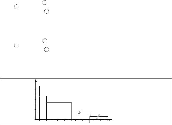
The battery charge cycle takes place in two steps (see figure 14):
–step 1: the battery is recharged at a constant current limited to 0.1C10 (i.e. 1/10th of the battery capacity specified for a 10 hour discharge). The DC voltage increases with the battery charge until the charge level is reached;
–step 2: the battery is recharged at constant voltage equal to the charge level (maximum value 463 V).
The charging current gradually decreases until reaching a specified low value (floating current).
For vented lead-acid batteries, the rectifier-charger supplies the charging voltage for 0 to 255 hours (parameter defined by the after-sales support department) and then the floating voltage. For sealed lead-acid batteries, the charging and floating voltages are the same.
Note:
If the Mains 1 failure is shorter than 0 to 255 seconds (parameter defined by the after-sales support department), the charger does not initiate a complete charge cycle but automatically supplies the floating voltage.
U/I |
voltage |
U charge/floating |
||
|
|
(sealed batteries) |
||
|
|
|
U "floating" |
|
|
|
|
(vented batteries) |
|
|
|
0.1 C10 |
|
|
|
|
current |
|
|
|
|
|
|
|
|
current |
constant voltage |
|
t |
|
limiting |
decreasing current |
|
|
Fig. 14
34006452EN/AC - Page 11
Introduction
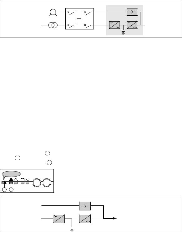
Installation with an engine generator set (figure 15)
If a stand-by generator is included in the installation, it is generally started automatically in the event of a Mains failure and connected to the main low voltage switchboard.
It is disconnected when Mains power is restored.
With such a system, the required battery time may be reduced to the time necessary for starting and bringing on line the stand-by generator.
The battery supplies power to the inverter during the transfers: Mains - generator and generator - Mains.
The transfer sequences described: Mains - battery - generator and generator - battery - Mains are fully automatic. They in no way affect the load and require no manual operation by the user.
Note:
To avoid load surges on the generator, the rectifier/charger is started with a 10 second maximum current consumption walk-in.
Example of an installation with an engine generator set
generator
G |
HV network
main LV |
switchboard |
Galaxy
mains 2
mains 1
Fig. 15
UPS shutdown or overload (systems with a static switch module) (figure 16)
Single-unit UPSs, modular UPSs or UPSs with an SSC:
– in the event of a UPS shutdown (initiated by the user or by an internal protective device), the load is automatically transferred to the Mains 2 bypass line. If transfer conditions are correct, transfer takes place instantly, without interruption to the load.
Note:
Transfer conditions are not correct when Mains 2 characteristics are outside tolerances (voltage: ±10 %; frequency as per personalization; phase sync with inverter ±3°);
–in the event of a major transient overload (greater than 160 % of the full load), immediate transfer takes place as above, without interruption to the load.
When the overload disappears, the load is automatically returned to the inverter depending on the configured value of the re-transfer counter: no return to inverter, or 1 to 255 (personalized value) overloads accepted before the load is permanently transferred to Mains 2. This operating mode allows start-up of load devices causing high inrush currents.
This system requires correct transfer conditions. If the conditions are not correct, the inverter will current limit to 150 % of its rated current for 1 second before stopping;
–in the event of a small but extended overload (i.e. a continuous level of power exceeding the full rated load), the inverter will continue to supply power for a period depending on the magnitude of the overload (10 minutes for a 125 % overload, 1 minute for a 150 % overload). See figure 17 (Overload curve);
–in all three of the above cases, the inverter shutsdown and supplies the load via Mains 2 with the following information on the control panel:
– |
green "load protected" light |
5 |
off, |
– buzzer 1 on, |
|
|
|
– |
red "load not protected" light |
2 |
on. |
beep...beep...
! |
! |
+ – |
1 2
IO
|
static switch |
mains 2 |
|
rectifier- |
inverter |
charger |
|
mains 1 |
load |
 battery
Fig. 16
34006452EN/AC - Page 12
Introduction
Frequency converters without redundancy
–in the event of a shutdown, the load is no longer supplied with power;
–in the event of a major transient overload (greater than 160 % of the rated load), the inverters will current limit to 160 % of their rated current for 1 second before stopping;
–in the event of a small but extended overload (i.e. a continuous level of power exceeding the full rated load), the inverters will continue to supply power for a period depending on the magnitude of the overload (10 minutes for a 125 % overload,
1 minute for a 150 % overload, see figure 17), and then stop;
–in all three of the above cases, inverter shutdown results in the following on the control panel of the concerned unit:
– |
green "load protected" light |
5 |
off, |
– buzzer 1 on, |
|
|
|
– |
red "load not protected" light |
2 |
on. |
Frequency converters with redundancy
– the shutdown of one unit is of no consequence for the load. The other lines each take up an equal amount of load power and the load continues to be supplied normally;
Inverter shutdown results in the following on the control panel of the concerned unit:
– |
green "load protected" light |
5 |
off, |
– buzzer 1 on, |
|
|
|
– |
red "load not protected" light |
2 |
on. |
– in the event of an overload, the system only loses its redundancy as long as the overload is less than the total rated power of the functioning units. If the overload is greater, the operating mode is that previously described for systems without redundancy.
Overload curve
|
I |
|
|
|
|
|
|
|
|
|
|
|
|
1,5 |
In |
|
|
|
|
|
|
|
|
|
|
|
|
1,35 |
In |
|
|
|
|
|
|
|
|
|
|
|
|
1,25 |
In |
|
|
|
|
|
|
|
|
|
|
|
|
1,10 |
In |
|
|
|
|
|
|
|
|
|
|
|
|
1,05 |
In |
|
|
|
|
|
|
|
|
|
|
|
|
|
In |
|
|
|
|
|
|
|
|
|
|
|
t (minutes) |
|
1 |
2 |
3 |
4 |
5 |
6 |
7 |
8 |
9 |
10 |
30 |
120 |
Fig. 17
Output voltage quality and continuity
The output voltage is stable in amplitude and frequency and is free of interruptions or transients outside specified tolerances, irrespective of Mains 1 or load disturbances (outages, load step changes, etc.).
Steady state voltage regulation:
For stable or slowly varying load conditions, the inverter output voltage is regulated to within ±0.5 % in amplitude.
The frequency of the output voltage can theoretically be regulated to within 0.1 % of the rated value, however the output frequency range may be intentionally extended to a maximum of ±2 Hz so that the inverter can remain synchronized with Mains 2 and its inherent frequency fluctuations, thus enabling transfer of the load to the bypass line at any time.
Note:
The output frequency range can be personalized and if necessary modified on the customer site by a qualified support technician from ±0.25 Hz to ±2 Hz in 0.25 Hz steps.
When the Mains 2 voltage moves outside this frequency range, the inverter is desynchronized and operates in "free running" mode, with the output frequency regulated to a high level of accuracy by a quartz oscillator.
When the Mains 2 frequency returns to within the specified tolerances, the inverter is gradually re-synchronized to the bypass line at a rate of 0.5 Hz to 2 Hz/s (as per the value personalized by the after-sales support department), thus avoiding exposing the load to sudden frequency variations.
Transient voltage regulation:
The inverter output voltage is not notably affected by instantaneous major variations in load characteristics.
This is due to the PWM (Pulse Width Modulation) chopping technique and the microprocessor-based regulation system that instantly compensates for any variation. In particular, the inverter output voltage remains within ±5 % of the rated voltage for load step changes of 25 to 100 % or of 100 to 25 %.
34006452EN/AC - Page 13

2. Description of MGETM GalaxyTM 9000 cubicles
2.1 Inverter cubicle
The rated outputs for MGETM GalaxyTM 9000 UPS’s (without parallel connection) or frequency converters are 800, 900 kVA.
Legend for figure 18
1- rectifier-charger (RC) module
2- inverter stack modules
3- rack for electronic control boards
4- static switch module (Single-unit or modular UPS)
4' - output static switch module (modular UPS, frequency converter or parallel UPS with SSC)
5- RC input fuses FU1-2-3
6- Mains 1 input switch Q1
7- protection fuses FU8 for the Mains 2 resistance/capacitance voltage surge protection network
8- Mains 2 input switch Q4S (Single-unit or modular UPS)
9- maintenance bypass switch Q3BP (Single-unit or modular UPS)
10- output switch Q5N
11- inverter output fuses FU 5-6-7
12- "Media Contacts 9" remote indications board
13- additional "Media Contacts 15" remote indications board (optional).
UPS or frequency converter
front view, doors open, protective covers removed
1 |
2 |
2 |
2 |
4' |
2 |
2 |
2 |
|
|
|
|
3 |
|
|
|
|
|
5 |
|
11 |
|
|
|
|
|
|
12 |
13 |
|
|
|
|
|
|
|
|
|
||
|
6 |
|
|
7 |
|
|
|
|
|
|
|
8 |
9 |
|
10 |
|
|
|
|
4 |
|
|
|
Fig. 18
34006452EN/AC - Page 14

Description of MGETM GalaxyTM 9000 cubicles
2.2 Static Switch Cubicle
Static Switch Cubicles are rated 500, 800, 1200 and 2000 kVA. Figure 19 presents the layout of components in these cubicles.
front view, doors open, protective covers removed |
|
||||
|
6 |
5 |
|
|
|
|
|
|
|
|
|
7 |
8 |
9 |
|
|
|
10 |
|
2 |
|
|
|
|
11 |
3 |
|
|
|
|
|
4 |
|
|
|
|
|
|
|
11 |
10 |
500 or 800kVA cubicle |
|
1200kVA cubicle |
|
||
|
|
5 |
|
2 |
|
|
|
|
|
|
|
|
|
|
7 |
|
|
|
|
8 |
9 |
3 |
|
|
|
|
|
||
|
|
6 |
10 |
|
|
|
|
|
11 |
4 |
|
|
|
|
|
|
|
2000kVA cubicle |
|
|
|
||
Legend for figure 19:
2- Mains 2 input switch Q4S,
3- maintenance bypass switch Q3BP,
4- output switch Q5N,
5- static switch module,
6- electronic control boards for the backup function,
7- protection fuses FU1 for the Mains 2 resistance/capacitance voltage surge protection network,
8- fuse switch Q1 (protection of the control electronics power supply against Mains 1),
9- fuse switch Q2 (protection of the control electronics power supply against Mains 2),
10- "Media Contacts 9" remote indications board,
11- additional "Media Contacts 15" remote indications board (optional).
Fig. 19
2.3 External maintenance bypass cubicle
Legend for figure 20:
1 - connection of auxiliary wires to indicate the positions of switches Q5N and Q3BP, 2 - maintenance bypass switch Q3BP,
3 - output switch Q5N.
1200kVA cubicle
Fig. 20
34006452EN/AC - Page 15
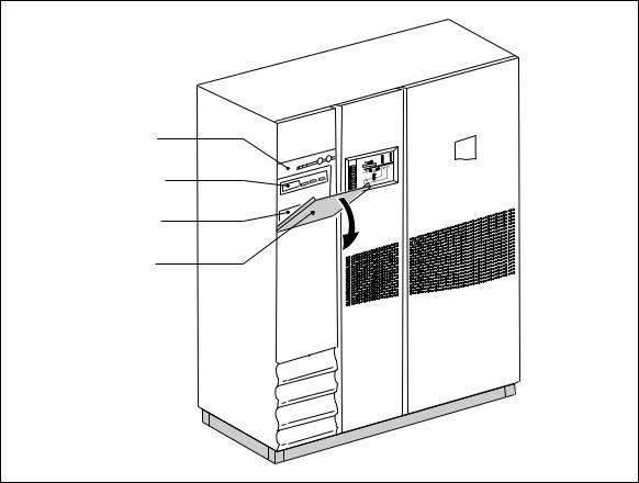
3. Control panel
MGETM GalaxyTM 9000 control panels (see figure 21) are made up of:
–a visible panel with the basic controls and indications required to check the general status of the system;
–a hidden panel with more detailed indications and more sophisticated control functions including an autodiagnostic system.
Note:
The information on the Mains 2 provided below does not concern frequency converters. Information on batteries does not concern frequency converters without batteries.
MGETM GalaxyTM 9000 control panel
visible panel
Monitor
hidden panel
cover
Fig. 21
34006452EN/AC - Page 16
Control panel
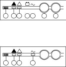
3.1 Visible control panel
Located in the upper left part of the cubicle front, the visible panel is designed to provide an easy and rapid overview of system status (see figures 22 and 23).
Interpretation of symbols is very simple and requires no particular training. The information concerns only the cubicle on which the panel is located. The panel indicates:
–normal operation (load protected);
–abnormal situations (operating problem);
–dangerous situations (load not protected);
–operation with load on battery power.
The control panel on the Static Switch Cubicle provides important information for the load:
–normal operation (load protected and supplied by the UPSs);
–abnormal situations (system malfunction);
–dangerous situations (load not protected).
Visible control panel (Inverter or frequency converter cubicle)
! |
! |
12 3
Fig. 22
+ – |
|
|
|
I |
|
O |
Legend for figure 22: |
||
|
|
|
|
1 |
- buzzer, |
||||
|
|
|
|
|
|
|
|
||
|
|
|
|
|
|
|
|
2 |
- "load not protected" light |
|
|
|
|
|
|
|
|
||
|
|
|
|
|
|
|
|
3 |
- "operating problem" light |
4 |
5 |
6 |
7 |
|
|||||
|
4 |
- "load on battery" light |
|||||||
|
|
|
|
|
|
|
|
||
|
|
|
|
|
|
|
|
5 |
- "load protected" light |
|
|
|
|
|
|
|
|
6 |
- "inverter on" button |
|
|
|
|
|
|
|
|
7 |
- "inverter off" button |
Visible control panel (Static Switch Cubicle)
|
! |
! |
|
1 |
2 |
3 |
5 |
Legend for figure 23: 1 - buzzer,
2 - "load not protected" light
3 - "operating problem" light
5 - "load protected" light
Fig. 23
34006452EN/AC - Page 17
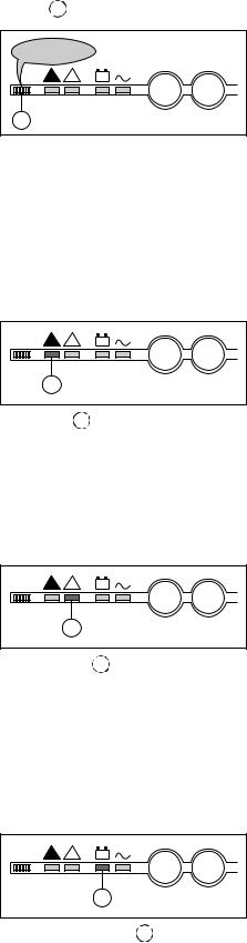
Control panel
Buzzer 1
beep...beep...
! |
! |
+ – |
1
IO
The buzzer sounds in the following situations:
–load supplied by Mains 2;
–load on battery;
–operating problems.
It beeps at a low decibel level and slow rate for minor problems and when the load is supplied from battery power. When the "low battery shutdown imminent" warning is received, the beeps increase in decibel level and rate.
Finally, if the inverter shuts down, the beep is loud and continuous. A buzzer reset button is located on the hidden control panel. If the buzzer is reset, a higher level alarm will set it on again.
"Load not protected" light
! |
! |
+ – |
2
This red light 2 signals that:
IO
–the load is supplied by Mains 2 following inverter shutdown (initiated by the user or by a protective device or a sudden overload) or the opening of the inverter output switch Q5N;
–battery circuit breaker QF1 has opened, thus making battery power unavailable.
Note:
In a parallel system, this light concerns only the specific UPS. The load may still be protected by the other lines.
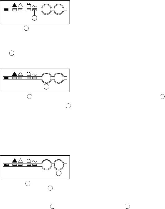
"Operating problem" light
! |
! |
+ – |
3
IO
This orange light 3 signals an operating problem or an environment fault, however the load is still supplied by the inverter.
–operating problems:
static switch ventilation fault, static switch control system fault;
–environment faults:
battery temperature outside tolerances, overload greater than 5 %;
–Mains 2 up but with voltage, frequency or phase characteristics outside tolerances with regards to the inverter.
"Battery operation" light
! |
! |
+ – |
4
IO
This blinking orange light 4 signals that the load is on battery power following:
–a Mains 1 outage or voltage drop;
–insufficient power on Mains 1, for example power supplied by an engine generator set requiring additional battery power;
–battery problem.
34006452EN/AC - Page 18
|
|
|
|
Control panel |
"Load protected" light |
|
|
||
! |
! |
+ – |
I |
O |
|
|
5 |
|
|
This green light |
5 signals that the load is supplied by the inverter and that the specified battery time is available in the event |
|||
of a Mains 1 outage. In short, it signals that the system is operating normally.
Note:
In parallel systems, this light concerns only the specific UPS.
The load may not be protected if it depends on the other lines. It is necessary to take into account all the "load protected" lights 5 for the different system lines or the light on the control panel of the Static Switch Cubicle, if it exists.
"Inverter on" button
! |
! |
+ – |
|
|
IO
6
This green button 6 is used to locally start the inverter. When it is pushed, the green "load protected" light 5 blinks for 3 seconds, indicating that the start-up order has been received. When the inverter has synchronized with Mains 2, it supplies the load and the green "load protected" light 5 remains on. The load is supplied by the UPS and the system is functioning normally. If the transfer to Mains 2 conditions are not correct (Mains 2 voltage, frequency or phase conditions outside tolerances), the inverter will not start and the system awaits a special order (see the "Hidden control panel" section).
Note:
–for modular UPSs with external maintenance bypass or parallel UPSs with SSC, transfer of the load to the inverters takes place only when the number of operating lines required to supply the load has been reached;
–for frequency converters, inverter start-up must take place with the load off or drawing a quantity of power equal to or less than that supplied by a single UPS.
"Inverter off" button
! |
! |
+ |
– |
I |
O |
|
|
|
|
|
7 |
This gray button 7 |
|
turns the inverter off. |
|||
– press the "inverter off" button 7 |
for 3 seconds; |
||||
–if the transfer to Mains 2 conditions are correct:
–the load is transferred without interrupting to Mains 2,
–the inverter shuts down,
– |
the green "load protected" light 5 goes off and the red "load not protected" light 2 goes on. |
– |
if the transfer to Mains 2 conditions are not correct, the button produces no effect. A special function on the hidden panel |
may be used to force the transfer.
Caution:
If the transfer is forced, the load will be subjected to a 0.8 second interruption in the supply of power.
Note:
–for Modular UPSs or parallel UPSs with SSC, the shutdown of an inverter may or may not result in the transfer of the load to Mains 2, depending on redundancy conditions;
–if the transfer to Mains 2 conditions are not correct or if the system does not have a Mains 2, the shutdown of a single inverter will result in the shutdown of the entire system if there is no redundancy.
34006452EN/AC - Page 19
 Loading...