


 Loading...
InRoom™
Precision Air Conditioner
Technical Data
ACPDX21-86, ACPCW40-150
American Power Conversion Legal Disclaimer
The information presented in this manual is not warranted by the American Power Conversion Corporation to be authoritative, error free, or complete. This publication is not meant to be a substitute for a detailed operational and site specific development plan. Therefore, American Power Conversion Corporation assumes no liability for damages, violations of codes, improper installation, system failures, or any other problems that could arise based on the use of this Publication.
The information contained in this Publication is provided as is and has been prepared solely for the purpose of evaluating data center design and construction. This Publication has been compiled in good faith by American Power Conversion Corporation. However, no representation is made or warranty given, either express or implied, as to the completeness or accuracy of the information this Publication contains.
IN NO EVENT SHALL AMERICAN POWER CONVERSION CORPORATION BE LIABLE FOR ANY DIRECT, INDIRECT, CONSEQUENTIAL, PUNITIVE, SPECIAL, OR INCIDENTAL DAMAGES (INCLUDING, WITHOUT LIMITATION, DAMAGES FOR LOSS OF BUSINESS, CONTRACT, REVENUE, DATA, INFORMATION, OR BUSINESS INTERRUPTION) RESULTING FROM, ARISING OUT, OR IN CONNECTION WITH THE USE OF, OR INABILITY TO USE THIS PUBLICATION OR THE CONTENT, EVEN IF AMERICAN POWER CONVERSION CORPORATION HAS BEEN EXPRESSLY ADVISED OF THE POSSIBILITY OF SUCH DAMAGES. AMERICAN POWER CONVERSION CORPORATION RESERVES THE RIGHT TO MAKE CHANGES OR UPDATES WITH RESPECT TO OR IN THE CONTENT OF THE PUBLICATION OR THE FORMAT THEREOF AT ANY TIME WITHOUT NOTICE.
Copyright, intellectual, and all other proprietary rights in the content (including but not limited to software, audio, video, text, and photographs) rests with American Power Conversion Corporation or its licensors. All rights in the content not expressly granted herein are reserved. No rights of any kind are licensed or assigned or shall otherwise pass to persons accessing this information.
This Publication shall not be for resale in whole or in part.

Contents
Overview ..................................................................................................... |
1 |
General . . . . . . . . . . . . . . . . . . . . . . . . . . . . . . . . . . . . . . . . . . . . . . . . . . . . . . |
.1 |
Scalable Solution for Critical Environments . . . . . . . . . . . . . . . . . . . . . . . . |
.2 |
Standard Features . . . . . . . . . . . . . . . . . . . . . . . . . . . . . . . . . . . . . . . . . . . . . |
.3 |
Optional Features. . . . . . . . . . . . . . . . . . . . . . . . . . . . . . . . . . . . . . . . . . . . . . |
.4 |
Condensers . . . . . . . . . . . . . . . . . . . . . . . . . . . . . . . . . . . . . . . . . . . . . . . . . . |
11 |
Display Interface . . . . . . . . . . . . . . . . . . . . . . . . . . . . . . . . . . . . . . . . . . . . . . |
18 |
InRoom Model Sizes . . . . . . . . . . . . . . . . . . . . . . . . . . . . . . . . . . . . . . . . . . . |
19 |
InRoom Cooling Unit Configurations. . . . . . . . . . . . . . . . . . . . . . . . . . . . . . |
20 |
60Hz Performance Specifications .......................................................... |
23 |
Chilled Water (CW) – 60Hz . . . . . . . . . . . . . . . . . . . . . . . . . . . . . . . . . . . . . . |
23 |
Air Cooled (DX) System – 60Hz . . . . . . . . . . . . . . . . . . . . . . . . . . . . . . . . . . |
25 |
MultiCool – Air Cooled (DX) with CW – 60Hz. . . . . . . . . . . . . . . . . . . . . . . . |
27 |
Fluid Cooled (Glycol 40%) – 60Hz . . . . . . . . . . . . . . . . . . . . . . . . . . . . . . . . |
30 |
Fluid Cooled (Glycol 0%) – 60Hz . . . . . . . . . . . . . . . . . . . . . . . . . . . . . . . . . |
32 |
Fluid Cooled (Glycol 0%) with CW – 60Hz . . . . . . . . . . . . . . . . . . . . . . . . . . |
34 |
Fluid Cooled (Glycol 40%) with CW – 60Hz . . . . . . . . . . . . . . . . . . . . . . . . . |
37 |
Fluid Cooled (Glycol 40%) with Economizer - 60Hz . . . . . . . . . . . . . . . . . . |
40 |
60Hz InRoom Electrical Specifications . . . . . . . . . . . . . . . . . . . . . . . . . . . . |
43 |
50Hz Performance Specifications .......................................................... |
45 |
Chilled Water (CW) - 50Hz . . . . . . . . . . . . . . . . . . . . . . . . . . . . . . . . . . . . . . . |
45 |
Air Cooled (DX) System - 50Hz . . . . . . . . . . . . . . . . . . . . . . . . . . . . . . . . . . . |
47 |
MultiCool - Air Cooled (DX) with CW - 50Hz . . . . . . . . . . . . . . . . . . . . . . . . |
49 |
Fluid Cooling (Glycol 40%) – 50Hz . . . . . . . . . . . . . . . . . . . . . . . . . . . . . . . . |
52 |
Fluid Cooled (Glycol 0%) – 50Hz . . . . . . . . . . . . . . . . . . . . . . . . . . . . . . . . . |
54 |
Fluid Cooled (Glycol 40%) with CW - 50Hz . . . . . . . . . . . . . . . . . . . . . . . . . |
56 |
Fluid Cooled (Glycol 40%) with Economizer - 50Hz . . . . . . . . . . . . . . . . . . |
59 |
50Hz InRoom Electrical Specifications . . . . . . . . . . . . . . . . . . . . . . . . . . . . |
62 |
General Specifications ............................................................................ |
63 |
Technical Specifications . . . . . . . . . . . . . . . . . . . . . . . . . . . . . . . . . . . . . . . . |
63 |
Transporting and Storage . . . . . . . . . . . . . . . . . . . . . . . . . . . . . . . . . . . . . . . |
64 |
Guidelines for Installation. . . . . . . . . . . . . . . . . . . . . . . . . . . . . . . . . . . . . . . |
65 |
Piping Connections . . . . . . . . . . . . . . . . . . . . . . . . . . . . . . . . . . . . . . . . . . . . |
67 |
InRoom Guide Specifications ................................................................. |
74 |
Warranty ................................................................................................... |
84 |
InRoom Precision AC Tech Data Manual |
i |
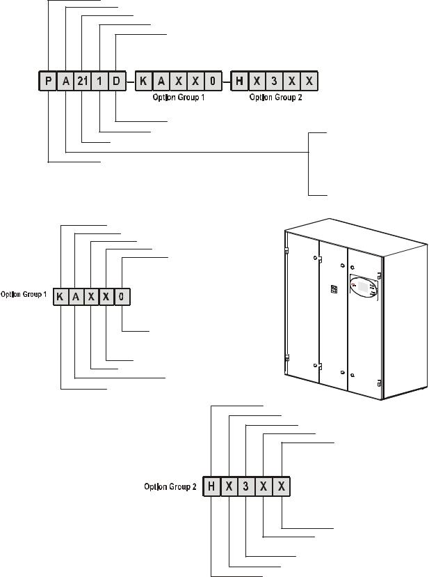
InRoom Nomenclature
Product Range
Cooling System
Model Size
Number of Refrigeration Circuits
Airflow Pattern
D - Downflow, U - Upflow 0, 1, 2
DX: 21, 31, 45, 61, 86 CW: 40, 66, 90, 110, 150
P = Perimeter unit
A: Air-cooled
G: Glycol-cooled
ACW: Air-cooled with MultiCool GCW: Glycol-cooled with MultiCool GE: Glycol-cooled with Economizer CW: Chilled Water
Voltage
Phase/Hertz
Reheat
Humidification
Mains Input Selection
|
0 |
- Standard Disconnect, |
|
1 |
- Dual Power with ATS *, |
|
2 |
- Dual Power without ATS **, |
X - None, E - Immersed Electrode |
||
X - None, E - Electric |
||
|
|
A: 3/60 |
B: 208-230V |
|
B: 3/50 |
G: 380-415V |
|
Refrigerant |
K: 460-480V |
|
|
M: 575-600V |
|
Head Pressure Control Valve |
Z: 400V |
|
Chilled Water Valve |
|
|
Hot Gas By-pass Valve |
|
|
Placeholder |
X - Reserved for Future Use
X - None
H - HGPV
X - None, 2 - 2-way, 3 - 3-way
X - None, 2 - 2-way, 3 - 3-way
X:None
H:R407C
na2868a
*Dual Power with ATS - Base Cooling Units without Heat and Humidifier with two Disconnects.
**Dual Power without ATS - Units with Heat and Humidifier with one Disconnect.
ii |
InRoom Precision AC Tech Data Manual |

Overview
General
The InRoom product family is an assemble to order (ATO) line of perimeter air conditioning systems that provide precision cooling for data centers and server rooms.
Precision environmental close control requirements now reach far beyond the confines of the traditional data center or computer room to encompass a larger suite of applications, referred to as technology rooms. Critical environment applications include:
•Computer rooms
•Telecommunication facilities
•Clean rooms
•Power equipment
•Medical equipment rooms
•Archives
•LAN/WAN environments
A worldwide network of APC representatives is fully qualified to provide engineering, sales, installation and service for our products.
APC warrants all parts for 1 year.
Models
The InRoom precision air conditioning unit is available in five sizes. The system is available in both chilled water and direct expansion for a combination of six heat rejection methods.
Select from ACPDX21-86 and ACPCW40-150.
Room Air Distribution
The InRoom downflow system draws warm exhaust air in through the top of the unit and cools it. The cool air is distributed back into the room through a raised floor plenum. These systems are ideal for areas with raised floors greater than 305 mm (10 in) high. Upflow systems draw warm exhaust air in through the front of the unit. The warm exhaust air is then cooled and discharged back into the room through a plenum or ductwork. Upflow systems are ideal for areas without a raised floor, but can also be used in a raised floor environment.
The InRoom precision air conditioner delivers high volume airflow to help eliminate hot spots in densely populated environments.
Configurations
•Air Cooled
•Air Cooled with Chilled Water Coil (MultiCool)
•Chilled Water Coil
•Fluid Cooled (Glycol)
•Fluid Cooled (Glycol) with Economizer Cooling Coil
•Fluid Cooled (Glycol) with Chilled Water Coil
Compliance Approval
1.ETL/CETL
2.NTRL Listed
3.Electrical Systems comply with NEC and UL 1995/ CSA22.2 No.236
C US
Standard Features
1.Insulated Cabinet
2.Direct Drive Fans
3.Electrical Panel
4.Main Power Disconnect Switch
5.Refrigeration System with Scroll Compressor and Crankcase Heater (DX only)
6.Redundant Group Control
7.Network Management Card
8.Electronic Expansion Valve (DX only)
9.Duct Flange (Upflow only)
10.30% ASHRAE Air Filters
11.Brazed plate condenser
12.2 or 3 Way Fluid Regulating Valves (Glycol models)
13.2 or 3 Way Fluid Regulating Valves (CW only)
14.Discrete Input/Output Interface
15.Resettable Circuit Breakers
16.Microprocessor Controller
17.Graphical User Interface
18.Electrically Commutated (EC) Fans
19.Stainless Steel Condensate Pan
20.Automatic Transfer Switches
Optional Features
1.Plenum
2.Sub-base Plenum
3.Floorstand
4.Seismic Floorstand
5.Immersed Electrode Humidifier
6.Condensate Pump
7.Electric Heat
8.Spot Water Detector(s)
9.Cable Water Detector(s) (60 Hz only)
10.Smoke Detector
11.Hot Gas Bypass Valve
InRoom Precision AC Tech Data Manual |
1 |
Scalable Solution for Critical Environments
Temperature and Humidity Design Conditions
Maintenance of temperature and humidity design conditions is critical to the smooth operation of a technology room. Based on ASHRAE TC9.9, the recommended design conditions for class one and class two environments should be 20–25°C (68–77°F) and 40–55% relative humidity (R.H.). Precision air conditioning is designed to maintain temperature at ±2°F and humidity at ±3–5% R.H. 24 hours a day, 365 days a year. Vapor barriers and sealed rooms are required to maintain these tolerances. In contrast, comfort systems are designed to maintain ±5°F from the temperature setpoint. There is usually no dedicated humidity control and the simple controllers cannot maintain the setpoint tolerance required for temperature, allowing potentially harmful temperature and humidity swings to occur. This is not acceptable for sensitive electronic equipment.
Air Quality
Precision air conditioners provide a high volume of air flow, around 600 CFM/ton (286 L/m, 150 CFM/kW). This high CFM moves more air through the space improving air distribution and reducing the chance of localized hot spots. It also allows more air to move through filters, ensuring a cleaner environment. This requires a moderate-to highefficiency filter bank to minimize airborne particles.
Low Humidity
Low humidity greatly increases the possibility of static electric discharges. Static discharges can corrupt data and damage hardware.
High Humidity
High humidity can result in tape surface deterioration, head crashes, condensation, corrosion, paper handling problems and gold and silver migration leading to component and board failure.
High & Low Temperature
A high or low temperature or rapid temperature swings can corrupt data processing and shut down an entire system. Temperature variations can alter the electrical and physical characteristics of electronic chips and other board components causing faulty operation or failure. These problems may be transient or may last for days. Transient problems can be very difficult to diagnose and repair.
Efficiency and Reliability
The use of energy efficient, direct drive fans along with fewer moving internal parts eliminate most potentials for failure. Scroll compressor technology provides unparalleled efficiency and constant, reliable operation with an ability to withstand liquid refrigerant ‘slugging’ which is a major cause of compressor failure. The compressor is also equipped with an internal high pressure sensor which opens a bypass valve in case of high pressure. This ensures internal pressure compensation takes place and damage to the compressor is avoided.
APC InRoom - The Right Solution
The APC InRoom cooling unit provides the maximum amount of precision cooling in a compact footprint with the lowest operating cost and noise level.
Dedicated Dehumidification Cycle
A dedicated dehumidification cycle allows the system to increase latent capacity without boosting compressor capacity, and also lowers the requirement for reheat. To achieve dehumidification, the electronic expansion valve is first partially closed. The reduction of the refrigerant mass flow makes the evaporation temperature drop, which lets the surface temperature in a part of the evaporator fall below the dew point of the air, causing dehumidification. For increased dehumidification, the fan speed is reduced. With a constant cooling capacity, the temperature of the air which flows through the heat exchanger coil passes below the dew point. The moisture contained in the air condenses on the heat exchanger, gathers in the condensate pan, and is carried away by the drain. To achieve humidification for the DX units with cabinet size 1 and all CW units, the fan speed is reduced. For the DX units with cabinet size 2–5, approximately one third of the evaporator is isolated from the refrigerant flow by a solenoid valve to achieve dehumidification by lowering the evaporator temperature below the dew point.
2 |
InRoom Precision AC Tech Data Manual |
Standard Features
Insulated Panels
The frame is constructed of 16 gauge steel sheet metal for maximum strength. All exterior panels and corner posts on the frame are powder coated for durability and an attractive finish. The side panels are double wall construction (inner and outer panels) with insulation between. The insulation is 12 mm (1/2 in) thick fiberglass. The walls isolate the insulation from the air stream and further reduce sound levels. Panels are hinged and removable for easy access. The cabinet is serviceable from the front of the unit.
Electronically Commutated (EC) Fans
Each unit is equipped with electronically commutated (EC) fan modules. This technology increases fan efficiency by up to 30% while reducing operating costs. Each fan module has an anti-vibration mounting to isolate it from the unit structure.
Electrical Panel
The electrical panel contains the contactors, starters, overload protection devices, and input power disconnects.
Main Power Disconnect Switch
A main power disconnect switch disconnects all high voltage power to the unit if necessary. The disconnect switch is accessible without removing the electric box cover.
Network Management Card
Permits multi-level access to monitoring, control, and event notification features over the building management network.
Refrigeration System and Compressor
The refrigeration system operates under a master controller for greater efficiency and accuracy. Suction and discharge pressures (DX models) are monitored and electronically controlled. The scroll compressors are designed for year-round operation with a 15-year life expectancy. The controller microprocessor provides real-time suction and discharge pressure readings reported by transducers installed on the refrigeration system.
For compressor protection, the InRoom precision air conditioner utilizes charge isolation and crank case heaters during off cycles (DX only). This eliminates the threat of liquid refrigerant migration that could lead to compressor slugging and lubrication issues.
Mains Automatic Transfer Switches
Mains automatic transfer switches allow two power sources to be connected to the cooling unit. A secondary power source (generator or UPS) can be automatically transferred in the event of a failure of the main power source to maintain cooling. Programmable switches are voltage adjustable with On and Off delay which can be adjusted from 0 to 20 seconds. The Off delay should be set to 3 seconds. Contact customer support for assistance to determine your requirements.
Duct Flange
A 25 mm (1 in) duct flange is included for the upflow units to provide convenient connection to external ductwork for either supply or return air as needed.
Evaporative Freeze Protection
Suction pressure is actively monitored by two individual sensors and controlled by the microprocessor controller to calculate the opening of the electronic expansion valve, eliminating the risk of condensate freeze-up on the evaporator coil.
Redundant Group Control
Allows up to 16 units to communicate with each other for redundancy, demand fighting prevention, and mode assist. Global sharing of certain settings requires a twisted pair shielded wiring interconnection.
30% ASHRAE 52.1 Filters
The filtration of conditioned air is extremely vital to maintaining the clean, particle-free environment required by electrical equipment. The system uses 30% (100 micron) filters, with full depth filter pleats. Deeper filters produce a lower pressure drop, requiring less energy during normal operation. Filters are replaceable through the front of the upflow unit and through the top of the downflow unit.
Condenser (Direct Expansion units only)
Standard air cooled condensers are suitable for cooling up to the maximum ambient temperature of either 35°C (95°F) or 46.1°C (115°F) depending on the requirement. These condensers have variable fan speed controls to allow operation down to -28.9°C (-20°F).
InRoom Precision AC Tech Data Manual |
3 |
Optional Features
Humidifier
The humidifier utilizes a pure steam generator specifically designed for precision environmental close control. The pure steam eliminates contaminating mineral deposits, potentially harmful bacteria, white dust, and excessive humidity. The humidifier requires little scheduled maintenance. The humidifier is proportionally controlled to meet the humidification demands of the conditioned space. Humidifier canisters are replaceable.
Electric Reheat
Electric reheat elements are low watt density, wired for 3-phase and loaded equally on all three phases, SCR controlled, and electrically and thermally protected by both automatic and manual reset thermal cut outs. Reheat coils are stainless steel, tubular fin construction.
Spot Water Detector
The solid-state spot water detector is available for both 50 and 60 Hz cooling units. The spot water detector activates an audible alarm on the controller when moisture is detected.
Smoke Detector
The factory-installed smoke detector is designed to sense smoke in the return air stream. Upon detection of smoke, an audible and visual alarm on the microprocessor controller will be activated and the unit will be shut down immediately.
Hot Gas Bypass Valve
The hot gas bypass valve (HGBV) adjusts the flow of compressor discharge gas to the evaporator coil at low load conditions to protect the coil from freezing and the compressor from excessive cycling. 60 Hz cooling units use a mechanical HGBV. 50 Hz cooling units use an electronically controlled HGBV. On 50 Hz cooling units, the HGBV option requires the analog extension board EAIO.
Cable Leak Detector (60 Hz only)
The optional 6 m (20 ft) leak detection sensing cable (APC part number ACAC75105) is available for 60 Hz cooling units only. The cable leak detector is placed on the floor or subfloor around all possible leak sources. If water or other conductive liquids contact the cable anywhere along its length, the master controller visually and audibly announces the leak.
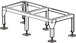
Floorstand
The floorstand raises the unit above the subfloor to match the height of the raised floor. Heights are available from 254 mm (10 in) to 610 mm (24 in) in 76.2 mm (3 in) increments and are adjustable +/– 38.1 mm (1.5 in). Adjustment is provided by threaded pedestals. Vibrationabsorbing pads are included. The floorstand, pedestal, and pads ship loose. In areas where earthquakes are a concern, seismic floorstands are available in 305 mm (12 in), 457 mm (18 in), and 610 mm (24 in) heights.
Plenums
Discharge plenums are available on upflow configurations. This application is recommended in rooms where raised floors are not available for air distribution. Discharge air should be ducted down cold aisles.
Base Plenum
Insulated base plenums are available for downflow cooling units where raised floors are not available for air distribution. Four front-discharge configurations are available equipped with dampers, grilles, flexible ductwork or open. All configurations are 450 mm (17.7 in) high and sit beneath the InRoom cooling unit.
Water Regulating Valves
Water and fluid cooled systems utilize twoor three-way valves to regulate the amount of water or glycol supplied to the condenser in response to refrigerant discharge pressure. The standard valve pressure rating is 28 kPa (400 psi).
Extreme Low Temperature Kit (Direct Expansion units only)
Extreme Low Temperature Kits for air cooled condensers are available for operation below –34.4°C (–30°F). The optional kit consists of pressure control valves and receivers for the liquid return side of the refrigerant piping.
4 |
InRoom Precision AC Tech Data Manual |
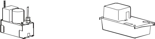
Condensate Pump
|
|
|
|
|
|
|
|
na2857a |
|
|
|
|
|
|
|
|
|
|
|
|
|
|
|
na2867a |
||
|
|
|
|
|
|
|
|
|
|
|
|
|
|
|
|
|
|
|
|
|
|
|
||||
|
|
|
|
|
|
|
|
|
|
|
|
|
|
|
|
|
|
|
|
|
|
|
||||
|
60 Hz |
|
|
|
|
|
|
|
|
|
|
|
|
|
|
|
|
|
50 Hz |
|
|
|||||
|
|
|
|
|
|
|
|
|
|
|
|
|
|
|
|
|
|
|
|
|
|
|
|
|
||
Model # |
|
|
|
|
ACAC75107 |
|
|
|
ACAC75107 |
|
|
ACAC76106 |
||||||||||||||
|
|
|
|
|
|
|
|
|
|
|
|
|
|
|
|
|
|
|
|
|
|
|
|
|
|
|
Hz |
|
|
|
|
60 |
|
|
|
|
|
|
60 |
|
|
|
|
50 |
|
|
|
|
|
||||
|
|
|
|
|
|
|
|
|
|
|
|
|
|
|
|
|
|
|
|
|
|
|
|
|
|
|
Height mm (in) |
|
|
|
|
259 |
(10 1/8) |
|
|
|
|
259 |
(10 1/8) |
|
|
|
210 (8 1/4) |
|
|
||||||||
|
|
|
|
|
|
|
|
|
|
|
|
|
|
|
|
|
|
|
|
|
|
|
|
|
|
|
Width mm (in) |
|
|
|
|
152 |
(6) |
|
|
|
|
152 |
(6) |
|
|
|
132 (5 1/4) |
|
|
||||||||
|
|
|
|
|
|
|
|
|
|
|
|
|
|
|
|
|
|
|
|
|
|
|
|
|
|
|
Length |
|
|
|
|
304 |
(12) |
|
|
|
|
304 |
(12) |
|
|
|
295 (11 1/2) |
|
|||||||||
|
|
|
|
|
|
|
|
|
|
|
|
|
|
|
|
|
|
|
|
|
|
|
|
|
|
|
Outlet mm (in) |
|
|
|
|
13 (1/2) |
|
|
|
|
13 (1/2) |
|
|
|
6 (1/4) |
|
|
|
|
||||||||
|
|
|
|
|
|
|
|
|
|
|
|
|
|
|
|
|
|
|
|
|
|
|
|
|
|
|
Volts |
|
|
|
|
230 |
|
|
|
|
|
460 |
|
|
|
|
400 |
|
|
|
|
||||||
|
|
|
|
|
|
|
|
|
|
|
|
|
|
|
|
|
|
|
|
|
|
|
|
|
|
|
Amps |
|
|
|
|
1.9 |
|
|
|
|
|
0.8 |
|
|
|
|
0.125 |
|
|
|
|
||||||
|
|
|
|
|
|
|
|
|
|
|
|
|
|
|
|
|
|
|
|
|
|
|
|
|
|
|
Watts |
|
|
|
|
360 |
|
|
|
|
|
360 |
|
|
|
|
30 |
|
|
|
|
|
|||||
|
|
|
|
|
|
|
|
|
|
|
|
|
|
|
|
|
|
|
|
|
|
|
|
|
|
|
Weight Kg (Lb) Ea |
|
5.8 (13) |
|
|
|
|
5.8 (13) |
|
|
|
3 (6.6) |
|
|
|
|
|||||||||||
|
|
|
|
|
|
|
|
|
|
|
|
|
|
|
|
|
|
|
|
|
|
|
|
|
|
|
HP (motor only) |
|
|
|
|
1/5 |
|
|
|
|
|
1/5 |
|
|
|
|
1/20 |
|
|
|
|
||||||
|
|
|
|
|
|
|
|
|
|
|
|
|
|
|
|
|
|
|
|
|
|
|
|
|
|
|
Tank Capacity Ltr (Gal) |
|
3.785 (1) |
|
|
|
|
3.785 (1) |
|
|
|
1.4 (1/3) |
|
|
|
|
|||||||||||
|
|
|
|
|
|
|
|
|
|
|
|
|
|
|
|
|
|
|
|
|
|
|
|
|
||
|
|
|
|
|
|
|
|
|
|
|
|
|
|
|
|
|
|
|
|
|
|
|
||||
|
Model |
|
|
|
|
|
|
Liters (Gallons) per hour at 60 Hz/Rated Voltage |
|
|
||||||||||||||||
|
|
|
|
|
|
|
|
|
|
Flow rate per pressure drop |
|
|
|
|
|
|
||||||||||
|
|
|
|
|
|
|
|
|
|
|
|
|
|
|
|
|
|
|
|
|
|
|
|
|||
|
|
|
|
|
|
1 ft |
|
|
|
5 ft |
|
10 ft |
15 ft |
|
20 ft |
30 ft |
|
|
40 ft |
|
||||||
|
|
|
|
|
|
|
|
|
|
|
|
|
|
|
|
|
|
|
|
|
||||||
|
ACAC75107 |
|
1839 (486) |
|
1714 (453) |
1559 (412) |
1407 (372) |
1275 (337) |
942 (249) |
635 (168) |
|
|||||||||||||||
|
|
|
|
|
|
|
|
|
|
|
|
|
|
|
|
|
|
|
|
|
||||||
|
ACAC75108 |
|
1589 (420) |
|
1438 (380) |
1343 (355) |
1248 (330) |
1173 (310) |
908 (240) |
548 (145) |
|
|||||||||||||||
|
|
|
|
|
|
|
|
|
|
|
|
|
|
|
|
|
|
|
|
|
|
|
|
|||
|
|
|
|
|
|
|
|
|
|
|
|
|
|
|
|
|
|
|
||||||||
|
|
|
|
|
Model |
|
|
|
Liters (Gallons) per hour at 50 Hz/Rated |
|
|
|
|
|
||||||||||||
|
|
|
|
|
|
|
|
Voltage - Flow rate per pressure drop |
|
|
|
|
|
|
||||||||||||
|
|
|
|
|
|
|
|
|
|
|
|
|
|
|
|
|
|
|
|
|
|
|
||||
|
|
|
|
|
|
|
|
|
|
|
1 m |
|
2 m |
3 m |
|
4 m |
|
|
|
|
|
|
||||
|
|
|
|
|
|
|
|
|
|
|
|
|
|
|
|
|
|
|||||||||
|
|
|
|
ACAC76106 |
|
135 (35.5) |
|
100 (26.4) |
60 (15.8) |
20 (5.3) |
|
|
|
|
|
|||||||||||
|
|
|
|
|
|
|
|
|
|
|
|
|
|
|
|
|
|
|
|
|
|
|
|
|
|
|
InRoom Precision AC Tech Data Manual |
5 |
Upflow Discharge Plenums for 50 Hz and 60 Hz InRoom Cooling Units
na2874a
Upflow discharge plenums
Cabinet size |
SKU |
Width |
Depth |
Height |
mm (in) |
mm (in) |
mm (in) |
||
|
|
|
|
|
1 |
ACPL75100 |
1000 (39.37) |
|
|
2 |
ACPL75101 |
1400 (55.11) |
|
|
|
|
|
900 (35) |
500 (19.7) |
3 |
ACPL75102 |
1750 (68.90) |
||
4 |
ACPL75103 |
2150 (84.65) |
|
|
5 |
ACPL75104 |
2550 (100.39) |
|
|
Note: Plenums are delivered completely assembled.
6 |
InRoom Precision AC Tech Data Manual |

Downflow Discharge Plenums for 50 Hz InRoom Cooling Units
|
|
|
|
na3026a |
Cabinet size |
SKU |
Width |
Depth |
Height |
mm (in) |
mm (in) |
mm (in) |
||
Unit Sub Base Plenum with no Grills |
|
|
||
1 |
ACSB76100 |
960 (37.8) |
|
|
2 |
ACSB76101 |
1360 (53.5) |
|
|
3 |
ACSB76102 |
1710 (67.3) |
865 (34) |
450 (17.7) |
4 |
ACSB76103 |
2110 (83.1) |
|
|
5 |
ACSB76104 |
2510 (98.8) |
|
|
Unit Sub Base Plenum with Grills |
|
|
||
1 |
ACSB76110 |
960 (37.8) |
|
|
2 |
ACSB76111 |
1360 (53.5) |
|
|
3 |
ACSB76112 |
1710 (67.3) |
865 (34) |
450 (17.7) |
4 |
ACSB76113 |
2110 (83.1) |
|
|
5 |
ACSB76114 |
2510 (98.8) |
|
|
Unit Sub Base Plenum with Damper (50Hz only) |
|
|
||
1 |
ACSB76120 |
960 (37.8) |
|
|
2 |
ACSB76121 |
1360 (53.5) |
|
|
3 |
ACSB76122 |
1710 (67.3) |
865 (34) |
450 (17.7) |
4 |
ACSB76123 |
2110 (83.1) |
|
|
5 |
ACSB76124 |
2510 (98.8) |
|
|
Unit Sub Base Plenum with Flex Connector (not shown) |
|
|||
1 |
ACSB76130 |
960 (37.8) |
|
|
2 |
ACSB76131 |
1360 (53.5) |
|
|
3 |
ACSB76132 |
1710 (67.3) |
865 (34) |
450 (17.7) |
4 |
ACSB76133 |
2110 (83.1) |
|
|
5 |
ACSB76134 |
2510 (98.8) |
|
|
Note:
•All three sub-base plenum models are attached to the cooling unit with 4x M10 screws.
•Sub-base plenums with grills are equipped with adjustable horizontal fins to direct exiting air.
•The plenums can be installed with the opening to the front or with the opening to the rear.
InRoom Precision AC Tech Data Manual |
7 |
Standard Floorstands for InRoom 60Hz Cooling Units
na2834a
Cabinet |
Model |
Height |
Width |
Depth |
size |
mm (in) |
mm (in) |
mm (in) |
|
|
|
|
|
|
|
ACFS76000 |
254 (10) |
960 (37.8) |
864 (34) |
|
ACFS76001 |
305 (12) |
|
|
1 |
|
|
|
|
ACFS76002 |
381 (15) |
|
|
|
|
ACFS76003 |
457 (18) |
|
|
|
ACFS76004 |
609 (24) |
|
|
|
ACFS76005 |
254 (10) |
1359 (53.5) |
864 (34) |
|
ACFS76006 |
305 (12) |
|
|
2 |
|
|
|
|
ACFS76007 |
381 (15) |
|
|
|
|
ACFS76008 |
457 (18) |
|
|
|
ACFS76009 |
609 (24) |
|
|
|
ACFS76010 |
254 (10) |
1712 (67.4) |
864 (34) |
|
ACFS76011 |
305 (12) |
|
|
3 |
|
|
|
|
ACFS76012 |
381 (15) |
|
|
|
|
ACFS76013 |
457 (18) |
|
|
|
ACFS76014 |
609 (24) |
|
|
|
ACFS76015 |
254 (10) |
2108 (83.0) |
864 (34) |
|
ACFS76016 |
305 (12) |
|
|
4 |
|
|
|
|
ACFS76017 |
381 (15) |
|
|
|
|
ACFS76018 |
457 (18) |
|
|
|
ACFS76019 |
609 (24) |
|
|
|
ACFS76020 |
254 (10) |
2512 (98.9) |
864 (34) |
|
ACFS76021 |
305 (12) |
|
|
5 |
|
|
|
|
ACFS76022 |
381 (15) |
|
|
|
|
ACFS76023 |
457 (18) |
|
|
|
ACFS76024 |
609 (24) |
|
|
8 |
InRoom Precision AC Tech Data Manual |
Bowling Alley Floorstands for InRoom 60Hz Cooling Units


 na3053a
Cabinet |
Model |
Height |
Width |
Depth |
|
size |
mm (in) |
mm (in) |
mm (in) |
||
|
|
|
|
|
|
|
ACFS76033 |
305 (12) |
|
|
|
1 |
ACFS76032 |
381 (15) |
960 (37.8) |
864 (34) |
|
ACFS76031 |
457 (18) |
||||
|
|
|
|||
|
ACFS76030 |
609 (24) |
|
|
|
|
ACFS76037 |
305 (12) |
|
|
|
2 |
ACFS76036 |
381 (15) |
1359 (53.5) |
864 (34) |
|
ACFS76035 |
457 (18) |
||||
|
|
|
|||
|
ACFS76034 |
609 (24) |
|
|
|
|
ACFS76041 |
305 (12) |
|
|
|
3 |
ACFS76040 |
381 (15) |
1712 (67.4) |
864 (34) |
|
ACFS76039 |
457 (18) |
||||
|
|
|
|||
|
ACFS76038 |
609 (24) |
|
|
|
|
ACFS76045 |
305 (12) |
|
|
|
4 |
ACFS76044 |
381 (15) |
2108 (83.0) |
864 (34) |
|
ACFS76043 |
457 (18) |
||||
|
|
|
|||
|
ACFS76042 |
609 (24) |
|
|
|
|
ACFS76049 |
305 (12) |
|
|
|
5 |
ACFS76048 |
381 (15) |
2512 (98.9) |
864 (34) |
|
ACFS76047 |
457 (18) |
||||
|
|
|
|||
|
ACFS76046 |
609 (24) |
|
|
InRoom Precision AC Tech Data Manual |
9 |
Floorstands for InRoom 50 HzCooling Units
 na3087a
Cabinet |
Model |
Height |
Width |
Depth |
size |
mm (in) |
mm (in) |
mm (in) |
|
|
|
|
|
|
1 |
ACFS76025 |
250-500 (10-20) |
960 (37.8) |
864 (34) |
2 |
ACFS76026 |
250-500 (10-20) |
1359 (53.5) |
864 (34) |
3 |
ACFS76027 |
250-500 (10-20) |
1712 (67.4) |
864 (34) |
4 |
ACFS76028 |
250-500 (10-20) |
2108 (83.0) |
864 (34) |
5 |
ACFS76029 |
250-500 (10-20) |
2512 (98.9) |
864 (34) |
10 |
InRoom Precision AC Tech Data Manual |
Condensers
Air cooled condensers are designed to reject heat from refrigerant based cooling equipment and are designed to be installed outdoors. The condensers are self-contained in a lighweight aluminum cabinet designed for mounting to a horizontal surface. The cabinet houses condenser coils and fan assemblies. Each condenser coil is a copper turb, aluminum finned coil.
The capacity of the condenser is based on the rated capacity of the coil. In the case of dual circuit units, the model number is based on the combined capacity of both coils. The coil is a closed-loop refrigerant condensing heat exchanger in which refrigerant is continuously circulated by the pressure differential created by a compressor.
The compressor increases refrigerant pressure to a level sufficiently high for it to be cooled and condensed into liquid by the effect of ambient air being drawn over the condenser coil. The fans have corrosion resistant, multi-blade impellers designed for high aerodynamic efficiency which results in lower power consumption, lower noise levels and longer life. Each fan utilizes a direct driven motor with maintenance free bearings. The fan motors are internally protected from overload. Fans have finger guard grilles to protect operators from injury and keep large tools or other objects from falling into the fan.
Electrical controls are in a weather proof enclosure and isolated from the rest of the equipment. The electrical box has a removable front access panel which is safety interlocked with the service disconnect switch, preventing the panel from being removed when the switch is in the ON position. The switch must be turned off to gain access to the electrical components.
60 Hz
na3012a
InRoom Precision AC Tech Data Manual |
11 |

InRoom Standard Condensers - 60 Hz
InRoom Remote Outdoor Condenser Data, 95°F ambient, 120°F condensation - R407C |
|
|||||
InRoom Cabinet Size |
1 |
2 |
3 |
4 |
5 |
|
Total Heat Rejection |
96.219 |
165.496 |
225.435 |
279.262 |
380.436 |
|
(THR) BTU/h |
||||||
|
|
|
|
|
||
CFM |
8,394 |
19,325 |
18,609 |
17,604 |
27,963 |
|
Fan Diameter - in |
19.69 |
24.80 |
24.80 |
24.80 |
24.80 |
|
Voltage Options |
|
|
|
|
|
|
208-230/3/60 |
ACCD76000 |
ACCD76004 |
ACCD76008 |
ACCD76012 |
ACCD76016 |
|
Number of Fans |
2 |
2 |
2 |
2 |
3 |
|
Fan RPM (Qty) |
1490 |
1585(1), 1500(1) |
1585(1), 1500(1) |
1585(1), 1500(1) |
1585(2), 1500(1) |
|
Motor HP (Qty) |
1.23 Hp(2) |
3.58(1), 3.85(1) |
3.58(1), 3.85(1) |
3.58(1), 3.85(1) |
3.58(2), 3.85(1) |
|
Electrical Data |
|
|
|
|
|
|
FLA |
8.6 |
19.7 |
19.7 |
19.7 |
29.1 |
|
MCA |
9.8 |
22.1 |
22.1 |
22.1 |
31.5 |
|
MFS |
15 |
30 |
30 |
30 |
40 |
|
460-480/3/60 |
ACCD76010 |
ACCD76005 |
ACCD76009 |
ACCD76013 |
ACCD76017 |
|
Number of Fans |
2 |
2 |
2 |
2 |
3 |
|
Fan RPM (Qty) |
1450(1), 1570(1)1650(1), 1500(1) |
1650(1), 1500(1) |
1650(1), 1500(1) |
1650(2), 1500(1) |
||
Motor HP (Qty) |
1.34(1), 1.64(1) |
3.90(1), 3.85(1) |
3.90(1), 3.85(1) |
3.90(1), 3.85(1) |
3.90(2), 3.85(1) |
|
Electrical Data |
|
|
|
|
|
|
FLA |
3.9 |
9.5 |
9.5 |
9.5 |
14.57 |
|
MCA |
4.3 |
10.7 |
10.7 |
10.7 |
15.85 |
|
MFS |
15 |
15 |
15 |
15 |
20 |
|
575-600/3/60 |
ACCD76022 |
ACCD76023 |
ACCD76024 |
ACCD76025 |
ACCD76026 |
|
Number of Fans |
2 |
2 |
2 |
2 |
3 |
|
Fan RPM (Qty) |
1450(1), 1570(1)1650(1), 1500(1) |
1650(1), 1500(1) |
1650(1), 1500(1) |
1650(2), 1500(1) |
||
Motor HP (Qty) |
1.34(1), 1.64(1) |
3.90(1), 3.85(1) |
3.90(1), 3.85(1) |
3.90(1), 3.85(1) |
3.90(2), 3.85(1) |
|
Electrical Data |
|
|
|
|
|
|
FLA |
3.4 |
8.0 |
8.0 |
8.0 |
12.3 |
|
MCA |
37 |
9.0 |
9.0 |
9.0 |
13.4 |
|
MFS |
15.0 |
15.0 |
15.0 |
15.0 |
15.0 |
|
Refrigerant Connections* |
|
|
|
|
|
|
Hot Gas Line - in |
1 1/8 OD |
1 1/8 OD |
1 3/8 OD |
1 3/8 OD |
1 5/8 OD |
|
Liquid Line - in |
7/8 OD |
7/8 OD |
1 1/8 OD |
1 1/8 OD |
1 3/8 OD |
|
Physical Data** |
|
|
|
|
|
|
Dimensions -HxWxD in |
35.5x32.75x76 |
48x108.5x48.25 |
48x108.5x48.25 |
48x108.5x48.25 |
48x155.5x48.25 |
|
Approximate Weight - lb. |
240 |
455 |
495 |
555 |
835 |
|
*Condenser connections may not represent actual line sizing.
**Dimensions are overall. Electrical enclosure and fan guard are included. Actual fan guard height is 4 in. Actual electrical enclosure depth is 6.5 in.
12 |
InRoom Precision AC Tech Data Manual |

InRoom Low Temperature (-30ºF) Condensers - 60 Hz
InRoom Remote Outdoor Condenser Data, 95°F ambient, 120°F condensation - R407C |
|
|||||
InRoom Cabinet Size |
1 |
2 |
3 |
4 |
5 |
|
Total Heat Rejection |
96.219 |
165.496 |
225.435 |
279.262 |
380.436 |
|
(THR) BTU/h |
||||||
|
|
|
|
|
||
CFM |
8,394 |
19,325 |
18,609 |
17,604 |
27,963 |
|
Fan Diameter - in |
19.69 |
24.80 |
24.80 |
24.80 |
24.80 |
|
Voltage Options |
|
|
|
|
|
|
208-230/3/60 |
ACCD76032 |
ACCD76033 |
ACCD76034 |
ACCD76035 |
ACCD76036 |
|
Number of Fans |
2 |
2 |
2 |
2 |
3 |
|
Fan RPM (Qty) |
1490 |
1585(1), 1500(1) |
1585(1), 1500(1) |
1585(1), 1500(1) |
1585(2), 1500(1) |
|
Motor HP (Qty) |
1.23(2) |
3.58(1), 3.85(1) |
3.58(1), 3.85(1) |
3.58(1), 3.85(1) |
3.58(2), 3.85(1) |
|
Electrical Data |
|
|
|
|
|
|
FLA |
8.6 |
19.7 |
19.7 |
19.7 |
29.1 |
|
MCA |
9.8 |
22.1 |
22.1 |
22.1 |
31.5 |
|
MFS |
15 |
30 |
30 |
30 |
40 |
|
460-480/3/60 |
ACCD76037 |
ACCD76038 |
ACCD76039 |
ACCD76040 |
ACCD76041 |
|
Number of Fans |
2 |
2 |
2 |
2 |
3 |
|
Fan RPM (Qty) |
1450(1), 1570(1)1650(1), 1500(1) |
1650(1), 1500(1) |
1650(1), 1500(1) |
1650(2), 1500(1) |
||
Motor HP (Qty) |
1.34(1), 1.64(1) |
3.90(1), 3.85(1) |
3.90(1), 3.85(1) |
3.90(1), 3.85(1) |
3.90(2), 3.85(1) |
|
Electrical Data |
|
|
|
|
|
|
FLA |
3.9 |
9.5 |
9.5 |
9.5 |
14.57 |
|
MCA |
4.3 |
10.7 |
10.7 |
10.7 |
15.85 |
|
MFS |
15 |
15 |
15 |
15 |
20 |
|
575-600/3/60 |
ACCD76042 |
ACCD76043 |
ACCD76044 |
ACCD76045 |
ACCD76046 |
|
Number of Fans |
2 |
2 |
2 |
2 |
3 |
|
Fan RPM (Qty) |
1450(1), 1570(1)1650(1), 1500(1) |
1650(1), 1500(1) |
1650(1), 1500(1) |
1650(2), 1500(1) |
||
Motor HP (Qty) |
1.34(1), 1.64(1) |
3.90(1), 3.85(1) |
3.90(1), 3.85(1) |
3.90(1), 3.85(1) |
3.90(2), 3.85(1) |
|
Electrical Data |
|
|
|
|
|
|
FLA |
3.7 |
8.3 |
8.3 |
8.3 |
12.8 |
|
MCA |
4.0 |
9.3 |
9.3 |
9.3 |
13.9 |
|
MFS |
15.0 |
15.0 |
15.0 |
15.0 |
15.0 |
|
Low Ambient Kit |
ACCD76106 |
ACCD76107 |
ACCD76109(2) |
ACCD76106(2) |
ACCD76107(2) |
|
Refrigerant Connections* |
|
|
|
|
|
|
Hot Gas Line - in |
1 1/8 OD |
1 1/8 OD |
1 3/8 OD |
1 3/8 OD |
1 5/8 OD |
|
Liquid Line - in |
7/8 OD |
7/8 OD |
1 1/8 OD |
1 1/8 OD |
1 3/8 OD |
|
Physical Data** |
|
|
|
|
|
|
Dimensions -HxWxD in |
35.5x32.75x76 |
48x108.5x48.25 |
48x108.5x48.25 |
48x108.5x48.25 |
48x155.5x48.25 |
|
Approximate Weight - lb. |
240 |
455 |
495 |
555 |
835 each |
|
*Condenser connections may not represent actual line sizing.
**Dimensions are overall. Electrical enclosure and fan guard are included. Actual fan guard height is 4 in. Actual electrical enclosure depth is 6.5 in.
InRoom Precision AC Tech Data Manual |
13 |
InRoom High Temperature Condensers - 60 Hz
InRoom Remote Outdoor Condenser Data, 105°F ambient, 125°F condensation - R407C |
|
|||||
InRoom Cabinet Size |
1 |
2 |
3 |
4 |
5 |
|
Total Heat Rejection |
154,105 |
247,501 |
331,845 |
448,600 |
331,845 (2) |
|
(THR) BTU/h |
||||||
|
|
|
|
|
||
CFM |
19,325 |
17,604 |
27,791 |
25,227 |
27,791 (2) |
|
Fan Diameter - in |
25.60 |
25.60 |
25.60 |
25.60 |
25.60 |
|
Voltage Options |
|
|
|
|
|
|
208-230/3/60 |
ACCD76004 |
ACCD76006 |
ACCD76016 |
ACCD76014 |
ACCD76020(2) |
|
Number of Fans |
2 |
2 |
3 |
3 |
3 |
|
Fan RPM (Qty) |
1585(1), 1500(1) |
1585(1), 1500(1) |
1585(2), 1500(1) |
1585(1), 1350(1) |
1585(2), 1500(1) |
|
Motor HP (Qty) |
3.58(1), 3.85(1) |
3.58(1), 3.85(1) |
3.58(2), 3.85(1) |
3.58(2), 3.75(1) |
3.58(2), 3.75(1) |
|
Electrical Data |
|
|
|
|
|
|
FLA |
19.7 |
19.7 |
29.1 |
29.1 |
29.1 |
|
MCA |
22.1 |
22.1 |
31.5 |
31.5 |
31.5 |
|
MFS |
30 |
30 |
40 |
40 |
40 |
|
460-480/3/60 |
ACCD76005 |
ACCD76007 |
ACCD76017 |
ACCD76015 |
ACCD76021(2) |
|
Number of Fans |
2 |
2 |
3 |
3 |
3 |
|
Fan RPM (Qty) |
1650(1), 1500(1) |
1650(1), 1500(1) |
1650(2), 1500(1) |
1650(2), 1350(1) |
1650(2), 1500(1) |
|
Motor HP (Qty) |
3.90(1), 3.85(1) |
3.90(1), 3.85(1) |
3.90(2), 3.85(1) |
3.90(2), 3.75(1) |
3.90(2), 3.85(1) |
|
Electrical Data |
|
|
|
|
|
|
FLA |
9.5 |
9.5 |
14.57 |
14.57 |
14.57 |
|
MCA |
10.7 |
10.7 |
15.85 |
15.85 |
15.85 |
|
MFS |
15 |
15 |
20 |
20 |
20 |
|
575-600/3/60 |
ACCD76027 |
ACCD76028 |
ACCD76029 |
ACCD76030 |
ACCD76031(2) |
|
Number of Fans |
2 |
2 |
3 |
3 |
3 |
|
Fan RPM (Qty) |
1650(1), 1500(1) |
1650(1), 1500(1) |
1650(2), 1500(1) |
1650(2), 1350(1) |
1650(2), 1500(1) |
|
Motor HP (Qty) |
3.90(1), 3.85(1) |
3.90(1), 3.85(1) |
3.90(2), 3.85(1) |
3.90(2), 3.75(1) |
3.90(2), 3.85(1) |
|
Electrical Data |
|
|
|
|
|
|
FLA |
8.0 |
8.0 |
12.3 |
12.3 |
12.3 (2) |
|
MCA |
9.0 |
9.0 |
13.4 |
13.4 |
13.4 (2) |
|
MFS |
15.0 |
15.0 |
15.0 |
15.0 |
15.0 |
|
Refrigerant Connections* |
|
|
|
|
|
|
Hot Gas Line - in |
1 1/8 OD |
1 5/8 OD |
1 5/8 OD |
1 5/8 OD |
2 1/8 OD |
|
Liquid Line - in |
7/8 OD |
1 3/8 OD |
1 3/8 OD |
1 3/8 OD |
2 1/8 OD |
|
Physical Data** |
|
|
|
|
|
|
Dimensions -HxWxD in |
48x108.5x48.25 |
48x108.5x48.25 |
48x155.5x48.25 |
48x155.5x48.25 |
48x155.5x48.25 |
|
Approximate Weight - lb. |
455 |
555 |
835 |
1000 |
835 (2) |
|
*Condenser connections may not represent actual line sizing.
**Dimensions are overall. Electrical enclosure and fan guard are included. Actual fan guard height is 4 in. Actual electrical enclosure depth is 6.5 in.
14 |
InRoom Precision AC Tech Data Manual |
InRoom Condensers - 50 Hz
50 Hz
na2856a
InRoom Remote Outdoor Condenser Data, 97°F ambient, 120°F condensation - R407C
InRoom Cabinet Size |
1 |
2 |
3 |
4 |
5 |
|
Condenser Model (Qty) |
ACCD76002 |
ACCD76003 |
ACCD76002 (2) |
ACCD76003 (2) |
ACCD76011(2) |
|
Voltage |
230/1/50 |
230/1/50 |
230/1/50 |
230/1/50 |
230/1/50 |
|
Number of Fans |
2 |
2 |
3 |
3 |
3 |
|
Airflow m3/h (cfm) |
13600 (8024) |
13000 (7670) |
13600 (8024) each |
13000 (7670) each |
16800 (9912) each |
|
Motor kW (HP) - |
2 x 0.69 |
2 x 0.69 |
2 x 0.69 |
2 x 0.69 |
3 x 0.69 |
|
(2 x 0.92) |
(2 x 0.92) |
(2 x 0.92) |
(2 x 0.92) |
(3 x 0.92) |
||
|
||||||
Refrigerant Connections* |
|
|
|
|
|
|
Hot Gas Line - in |
7/8 OD |
7/8 OD |
7/8 OD |
1 3/8 OD |
7/8 OD |
|
Liquid Line - in |
7/8 OD |
7/8 OD |
7/8 OD |
7/8 OD |
7/8 OD |
|
Weight - kg (lb) |
72 (158) |
81 (178) |
2 x 72 (2 x 158) |
2 x 81 (2 x 178) |
2 x 144 (2 x 317) |
|
InRoom Remote Outdoor |
Condenser Data, 115°F ambient, 131°F condensation - R407C |
|
||||
Condenser Model (Qty) |
ACCD76003 |
ACCD76011 |
ACCD76001 (2) |
ACCD76011 (2) |
ACCD76019(2) |
|
Voltage |
230/1/50 |
230/1/50 |
230/1/50 |
230/1/50 |
230/1/50 |
|
Number of Fans |
2 |
2 |
3 |
3 |
3 |
|
Airflow m3/h (cfm) |
13000 (7670) |
16800 (9912) |
13000 (7670) each |
16800 (9912) each |
24000 (14160) each |
|
Motor kW (HP) - |
2 x 0.69 |
3 x 0.69 |
2 x 0.69 |
2 x 0.69 |
3 x 0.62 |
|
(2 x 0.92) |
(3 x 0.92) |
(2 x 0.92) |
(2 x 0.92) |
(3 x 0.83) |
||
|
||||||
Refrigerant Connections* |
|
|
|
|
|
|
Hot Gas Line - in |
7/8 OD |
7/8 OD |
7/8 OD |
7/8 OD |
1 3/8 OD |
|
Liquid Line - in |
7/8 OD |
7/8 OD |
7/8 OD |
7/8 OD |
7/8 OD |
|
Weight - kg (lb) |
81 (178) |
144 (317) |
2 x 81 (2 x 178) |
2 x 144 (2 x 317) |
2 x 200 (2 x 440) |
|
* Condenser connections may not represent actual line sizing.
InRoom Precision AC Tech Data Manual |
15 |
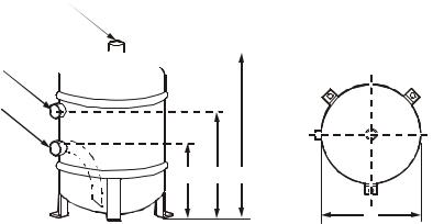
Receivers
Conformance. Each receiver conforms to UL, CSA or ASME requirements for 450 psi maximum working pressure. Models with an internal diameter under six inches are UL listed. All larger models are made according to ASME code and labeled appropriately.
Pumpdown and refrigerant charge. All pumpdowns are calculated at 80% capacity of liquid. Approximately 10% of pumpdown capacity is required to operate the receiver properly.
Pumpdown = (overall length – length correction) x (pumpdown per inch)
Overall length = (pumpdown required / pumpdown per inch) = (length correction)
60 Hz |
S (Safety) |
|
P (Refrigerant Inlet)
Q (Refrigerant Outlet)
A B H
D
na2892a
InRoom Cabinet Size |
1 |
2 |
3 |
4 |
5 |
|||
60 Hz Air-Cooled |
ACCD76032 |
ACCD76033 |
ACCD76034 |
ACCD76035 |
ACCD76036 |
|||
ACCD76037 |
ACCD76038 |
ACCD76039 |
ACCD76040 |
ACCD76041 |
||||
Condenser Model |
||||||||
ACCD76042 |
ACCD76043 |
ACCD76044 |
ACCD76045 |
ACCD76046 |
||||
|
||||||||
|
|
|
|
|
|
|||
60 Hz Receiver Model (Qty) |
ACAC76106 |
ACAC76107 |
ACAC76109 (2) |
ACAC76106 (2) |
ACAC76107 (2) |
|||
Pumpdown capacities for R- |
11.79 (26) |
19.58 (44) |
8.1 (18) each |
11.79 (26) each |
27.7 (61) each |
|||
407C kg (lb) * |
||||||||
|
|
|
|
|
|
|
||
|
|
|
|
|
|
|
|
|
Length correction mm (in) |
45.7 |
(1.8) |
58.4 |
(2.3) |
45.7 (1.8) |
45.7 (1.8) |
66 (2.6) |
|
End to weld mm (in) |
79.4 (3 1/8) |
114.3 (4 1/2) |
79.4 (3 1/8) |
79.4 (3 1/8) |
139.7 (5 1/2) |
|||
D (OD) mm (in) |
219 (8 5/8) |
273 (10 3/4) |
219 (8 5/8) |
219 (8 5/8) |
324 (12 3/4) |
|||
H mm (in) |
406.4 (16) |
457.2 (18) |
304.8 (12) |
406.4 (16) |
457.2 (18) |
|||
A mm (in) |
127 (5) |
152.4 (6) |
127 (5) |
127 (5) |
168.2 (6 5/8) |
|||
B mm (in) |
279.4 (11) |
292.1 (11 1/2) |
177.8 (7) |
279.4 (11) |
288.8 (11 3/8) |
|||
P (ID) mm (in) |
15.9 |
(5/8) |
28.4 (1 1/8) |
15.9 (5/8) |
15.9 (5/8) |
28.4 (1 1/8) |
||
Q (ID) mm (in) |
15.9 |
(5/8) |
22.2 |
(7/8) |
15.9 (5/8) |
15.9 (5/8) |
28.4 (1 1/8) |
|
S (FPT) mm (in) |
9.5 (3/8) |
22.2 |
(7/8) |
9.5 (3/8) |
9.5 (3/8) |
12.7 (1/2) |
||
Shipping Weight kg (lb) |
15.87 (35) |
27.2 (60) |
13.15 (29) each |
15.87 (35) each |
36.28 (80) each |
|||
Receiver Heater |
|
|
|
|
|
|
|
|
|
|
|
|
|
|
|||
Watts |
125 |
125 |
200 |
125 (2) |
125 (2) |
|||
Heater Width - mm (in) |
25 |
(1) |
25 |
(1) |
25 (1) |
25 (1) |
25 (1) |
|
Heater Length - mm (in) |
635 |
(25) |
635 |
(25) |
1015 (40) |
635 (25) |
635 (25) |
|
Lead Length - mm (in) ** |
305 |
(12) |
305 |
(12) |
305 (12) |
305 (12) |
305 (12) |
|
Thermostat Setting |
60/75 |
60/75 |
60/75 |
60/75 |
60/75 |
|||
*All pumpdowns are calculated at 80% of receiver volume.
**12 inches, UL 1180, Teflon® silicon rubber wire, round elements, rated @ 5 Watts per square inch
16 |
InRoom Precision AC Tech Data Manual |
InRoom Receivers - 50 Hz
50 Hz
InRoom Cabinet Size |
|
1 |
2 |
3 |
4 |
5 |
|
50 Hz Air-Cooled |
ACCD76002 |
ACCD76003 |
ACCD76002 (2) |
ACCD76003 (2) |
ACCD76011 (2) |
||
Condenser Model |
|||||||
|
|
|
|
|
|
||
|
|
|
|
|
|
||
50 Hz Receiver Model (Qty) |
ACAC76101 |
ACAC76102 |
ACAC76103 (2) |
ACAC76104 (2) |
ACAC76105 (2) |
||
Max Refrigerant Charge 90% |
|
|
|
|
|
|
|
at 20°C (68°F) |
24.0 (53) |
24.0 (53) |
24.0 (53) each |
24.0 (53) each |
24.0 (53) each |
||
R-407C kg (lb) * |
|
|
|
|
|
|
|
|
|
|
|
|
|
|
|
Connection inlet - mm (in) |
22 |
(7/8) |
22 (7/8) |
22 (7/8) |
22 (7/8) |
22 (7/8) |
|
Connection thread/flange |
1 1/4 in |
1 1/4 in |
1 1/4 in |
1 1/4 in |
1 1/4 in |
||
(12 UNF) |
(12 UNF) |
(12 UNF) |
(12 UNF) |
(12 UNF) |
|||
|
|||||||
|
|
|
|
|
|
|
|
Connection outlet - mm (in) |
22 |
(7/8) |
22 (7/8) |
22 (7/8) |
22 (7/8) |
22 (7/8) |
|
Gauge |
7/16 (20 UNF) |
7/16 (20 UNF) |
7/16 (20 UNF) |
7/16 (20 UNF) |
7/16 (20 UNF) |
||
Pressure relief valve |
1 1/4 in |
1 1/4 in |
1 1/4 in |
1 1/4 in |
1 1/4 in |
||
connection |
(12 UNF) |
(12 UNF) |
(12 UNF) |
(12 UNF) |
(12 UNF) |
||
|
|
|
|
|
|
|
|
Height - mm (in) |
287 |
(11.3) |
287 (11.3) |
287 (11.3) each |
287 (11.3) each |
287 (11.3) each |
|
Depth - mm (in) |
276 |
(10.9) |
276 (10.9) |
276 (10.9) each |
276 (10.9) each |
276 (10.9) each |
|
Width - mm (in) |
824 |
(32.4) |
824 (32.4) |
824 (32.4) each |
824 (32.4) each |
824 (32.4) each |
|
Weight - kg (lb) |
23.6 (52) |
23.6 (52) |
23.6 (52) each |
23.6 (52) each |
23.6 (52)each |
||
InRoom Precision AC Tech Data Manual |
17 |
Display Interface
The display interface is standard on each system. The display interface provides precision control for the demanding requirements of these environments:
•Data centers
•Control rooms
•Clean rooms
•Switch rooms
•UPS rooms
 na2773a
The easy-to-use display allows the operator to select options from the display interface to control and monitor the InRoom precision air conditioning system.
Logging
The display interface displays the most recent alarms. Each alarm log contains a time/date stamp as well as operating conditions at the time of occurrence. The display interface also displays run time, in hours, for major components (compressors, heaters, humidifier, fans).
Control Type
The display interface utilizes proportional and integral derivative (PID), a time-proven precision environmental control method. This allows for custom tuning of control variables to achieve the desired system response.
Functions
•Audible and Visual Alarms
•Sensor Status (Temperature, Humidity, and Pressure)
•Component State (On/Off, %)
•Component Runtimes
•Event Logging
•Configuration and Alarm Settings
•Password Protection
Open Architecture
The InRoom precision air conditioning system is open for integration with all building management systems. The display interface on the system supports Modbus RTU RS485.
Alarms
• |
Local Stop |
• |
External Alarm |
• Room Humidity Too Low |
|
• |
Compressor Low Pressure |
• |
Pump Failure |
• Supply Temp Too Low |
|
• |
Compressor Failure |
• |
Drycooler Failure |
• Supply Humidity Too Low |
|
• |
E-heating Failure |
• |
Water Detector |
• Water Temp Too High |
|
• |
Humidifier Failure |
• Room Temp Too High |
• Water Temp Too Low |
||
• |
Humidifier 5uS |
• Room Humidity Too High |
• |
Fire/Smoke Detector |
|
• |
Humidifier 20uS |
• Supply Temp Too High |
• |
Sensor Failure |
|
• |
Fan Error |
• Supply Humidity Too High |
• |
Sensor Broken |
|
• |
Filter Clocked |
• Room Temp Too Low |
|
|
|
18 |
InRoom Precision AC Tech Data Manual |

InRoom Model Sizes
Different variations of the InRoom product range are defined by the airflow direction, the number of refrigerant circuits, and the type of cooling system. There are five cabinet sizes. The front service access for all cabinet sizes of the InRoom Precision Air Conditioner is 1 m (39 in).
The InRoom Fluid Cooled (Glycol) system with Economizer Coil differs from the other versions by having a larger cabinet size, not a larger capacity. There are no Fluid Cooled (Glycol ) systems with Economizer Coils in Cabinet Size 1.
1
1980
(77.95)
1000
(39.37)
2 |
1400 |
(55.11) |
3 |
1750 |
(68.90) |
*Dimensions are in mm (in).
Depth of all models is 890 mm (35 in).
4 |
5 |
|
|
|
|
|
|
|
1980
(77.95)
n a 2 8 3 5 a
2150 |
2550 |
(84.65) |
(100.39) |
InRoom Direct Expansion Model Sizes
Cabinet Size |
1 |
2 |
3 |
4 |
5 |
|
|
|
|
|
|
|
PA211 |
PA311 |
|
|
|
1 refrigerant circuit |
PG211 |
PG311 |
|
|
|
PACW211 |
PACW311 |
|
|
|
|
|
|
|
|
||
|
PGCW211 |
PGCW311 |
|
|
|
|
|
|
|
|
|
|
|
|
PA452 |
PA612 |
PA862 |
2 refrigerant circuits |
|
|
PG452 |
PG612 |
PG862 |
|
|
PACW452 |
PACW612 |
PACW862 |
|
|
|
|
|||
|
|
|
PGCW452 |
PGCW612 |
PGCW862 |
|
|
|
|
|
|
InRoom Fluid Cooled (Glycol) with Economizer Model Sizes |
|
|
|||
|
|
|
|
|
|
1 refrigerant circuit |
|
PGE211 |
PGE311 |
|
|
|
|
|
|
|
|
2 refrigerant circuits |
|
|
|
PGE452 |
PGE612 |
|
|
|
|
|
|
InRoom Chilled Water Model Sizes |
|
|
|
|
|
|
|
|
|
|
|
|
PCW400 |
PCW660 |
PCW900 |
PCW1100 |
PCW1500 |
|
|
|
|
|
|
InRoom Precision AC Tech Data Manual |
19 |
InRoom Cooling Unit Configurations
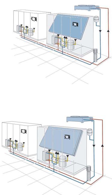
Fluid Cooled (Glycol)
InRoom Fluid Cooled (Glycol) systems are completely charged and factory tested in a sealed system for reliability. In mid to low ambient climates, an economizer coil can be used to increase efficiency and extend compressor life. Economizer operation greatly reduces the energy consumption of the system. Water regulating valves control head pressure.
•System is used with a fluid cooler.
•Factory-tested as a sealed system.
•Eliminates the need for field refrigerant piping.
•No requirement for water treatment.
•Economizer option provides high efficiency.
•Low maintenance.
The InRoom Fluid Cooled (Glycol) System with Economizer is configured with both the glycol factory sealed system and an Economizer coil. During cold ambient conditions, the compressorized system will shut down and utilize the cold outdoor air to cool the glycol system, rerouting it from the heat exchanger to the Economizer coil for efficient operation.
Fluid Cooled (Glycol) System
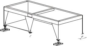
na2836a
Fluid Cooled (Glycol) System with Economizer
na2837a
20 |
InRoom Precision AC Tech Data Manual |
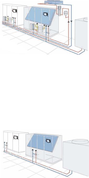
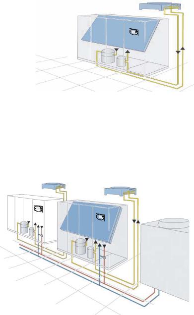
The InRoom Fluid Cooled (Glycol) System with Chilled Water System is a combination of a factory sealed glycol system and a chilled water system and contains two separate cooling coils. The controller microprocessor manages the systems to allow the glycol system to operate as standby to the chilled water system or vice versa, giving the added security of back-up cooling to the computer room.
Chilled Water
InRoom Chilled Water systems are available in a packaged fan-coil design. Room air is recirculated through the cooling coil, which transfers the heat load directly into the chilled water ring main. Water flow rate is regulated by a 2- or 3-way valve controlled by the controller microprocessor. Cooling towers are used as a source of heat rejection and can be used to serve multiple indoor units. Towers utilizing outdoor air require water treatment.
•The system is used with a cooling tower or other source of water.
•Factory sealed and tested system.
•The need for field refrigerant piping is eliminated.
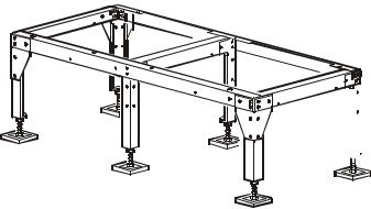
na2843a
Fluid Cooled (Glycol) System with
Chilled Water Cooling System
na2844a
Chilled Water Cooling System
InRoom Precision AC Tech Data Manual |
21 |
Air Cooled (DX)
Air cooled systems are not pre-charged from the factory and require field refrigerant piping. Each installation requires an engineered piping solution. APC strongly recommends installation by a highly qualified refrigeration contractor to avoid improper elevation and long piping runs. The Air Cooled system uses refrigerant as the heat transfer medium. Room air recirculates through the InRoom unit which houses the evaporator coil, scroll compressor, and refrigeration system. A remotely mounted aircooled condenser is connected to the unit. The sealed refrigeration circuit will absorb the room heat load and reject it to the outside atmosphere.
•System used with a remote air cooled condenser
•Field installed refrigerant piping is required
•Low maintenance
The MultiCool System is a combination of the Air Cooled System and the Chilled Water System and contains two separate cooling coils. The controller microprocessor manages the MultiCool System to allow the air cooled by the Air Cooled system to operate as a standby system to the Chilled Water (CW) system or vice versa, giving the added security of back-up cooling to the computer room.
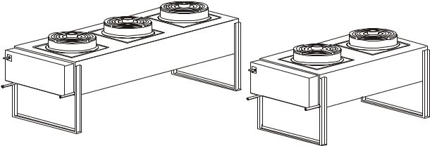
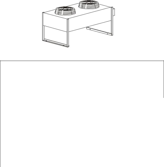
na2845a
Air Cooled System
na2846a
MultiCool - Air Cooled System with Chilled Water Cooling System
22 |
InRoom Precision AC Tech Data Manual |

60Hz Performance Specifications
Chilled Water (CW) – 60Hz
Chilled Water |
PCW400 |
PCW660 |
PCW900 |
PCW1100 |
PCW1500 |
|||||||
|
Cabinet Size 1 |
Cabinet Size 2 |
Cabinet Size 3 |
Cabinet Size 4 |
Cabinet Size 5 |
|||||||
|
|
|
|
|
|
|
|
|
|
|
||
26.7°C DB, 19.4°C WB (80°F DB, 67°F WB) 50% RH |
|
|
|
|
|
|
|
|
|
|
||
Total - kW (BTU/hr) |
53.6 |
(182,800) |
86.1 |
(293,800) |
120.1 (409,800) |
153.4 |
(553,400) |
197.8 |
(675,000) |
|||
Sensible - kW (BTU/hr) |
35.8 |
(128,999) |
58.4 |
(206,099) |
82.7 |
(288,999) |
102.4 |
(356,199) |
134.3 |
(465,099) |
||
Flow Rate - L/m (GPM) |
139.3 (36.8) |
229.4 (60.6) |
324.0 (85.6) |
410.3 |
(108.4) |
534.1 |
(141.0) |
|||||
Total Pressure Drop Water Side - Kpa (ft) |
91.8 |
(30.7) |
129.2 (43.2) |
112.1 (37.5) |
124.7 |
(41.7) |
189.0 |
(63.2) |
||||
23.9°C DB, 16.9°C WB (75°F DB, 62.5°F WB) 50% RH |
|
|
|
|
|
|
|
|
|
|
||
Total - kW (BTU/hr) |
29.4 |
(100,300) |
54.5 |
(186,000) |
65.5 |
(223,500) |
82.5 |
(281,500) |
104.8 |
(357,600) |
||
Sensible - kW (BTU/hr) * |
25.5 |
(93,799) |
45.5 |
(162,099) |
59.1 |
(208,499) |
73.9 |
(258,999) |
95.3 |
(331,999) |
||
Flow Rate - L/m (GPM) |
80.3 |
(21.2) |
147.6 (39.0) |
182.8 (48.3) |
227.1 |
(60.0) |
293.4 |
(77.5) |
||||
Total Pressure Drop Water Side - Kpa (ft) |
29.6 |
(9.9) |
62.8 |
(21.0) |
38.9 |
(13.0) |
43.4 |
(14.5) |
59.8 |
(20.0) |
||
23.9°C DB, 16.1°C WB (75°F DB, 61°F WB) 45% RH |
|
|
|
|
|
|
|
|
|
|
||
Total - kW (BTU/hr) |
29.9 |
(102,000) |
49.8 |
(169,900) |
66.3 |
(226,200) |
82.2 |
(280,500) |
105.8 |
(361,000) |
||
Sensible - kW (BTU/hr) |
27.9 |
(101,999) |
47.8 |
(169,899) |
64.3 |
(226,199) |
80.2 |
(280,499) |
103.8 |
(360,999) |
||
Flow Rate - L/m (GPM) |
81.4 |
(21.5) |
135.5 (35.8) |
185.1 (48.9) |
226.4 |
(59.8) |
296.0 |
(78.2) |
||||
Total Pressure Drop Water Side - Kpa (ft) |
31.4 |
(10.5) |
52.3 |
(17.5) |
39.5 |
(13.2) |
43.1 |
(14.54) |
60.4 |
(20.2) |
||
22.2°C DB, 15.5°C WB (72°F DB, 60°F WB) 50% RH |
|
|
|
|
|
|
|
|
|
|
||
Total - kW (BTU/hr) |
25.0 |
(85,300) |
42.0 |
(143,300) |
54.8 |
(187,000) |
68.2 |
(232,700) |
86.3 |
(294,500) |
||
Sensible - kW (BTU/hr) |
23.0 |
(85,299) |
40.0 |
(143,299) |
52.8 |
(186,999) |
66.2 |
(232,699) |
84.3 |
(294,499) |
||
Flow Rate - L/m (GPM) |
68.9 |
(18.2) |
115.1 (30.4) |
155.2 (41.0) |
190.0 |
(50.2) |
245.7 |
(64.9) |
||||
Total Pressure Drop Water Side - Kpa (ft) |
22.4 |
(7.5) |
39.8 |
(13.3) |
28.4 |
(9.5) |
31.1 |
(10.4) |
42.5 |
(14.2) |
||
22.2°C DB, 14.8°C WB (72°F DB, 58.6°F WB) 45% RH |
|
|
|
|
|
|
|
|
|
|
||
Total - kW (BTU/hr) |
25.0 |
(85,300) |
42.0 |
(143,300) |
54.8 |
(187,000) |
68.2 |
(232,700) |
86.3 |
(294,500) |
||
Sensible - kW (BTU/hr) |
23.0 |
(85,299) |
40.0 |
(143,299) |
52.8 |
(186,999) |
66.2 |
(232,699) |
84.3 |
(294,499) |
||
Flow Rate - L/m (GPM) |
68.9 |
(18.2) |
115.1 (30.4) |
155.2 (41.0) |
190.0 |
(50.2) |
245.7 |
(64.9) |
||||
Total Pressure Drop Water Side - Kpa (ft) |
22.4 |
(7.5) |
39.8 |
(13.3) |
28.4 |
(9.5) |
31.1 |
(10.4) |
42.5 |
(14.2) |
||
21.1°C DB, 14.0°C WB(70°F DB, 58.5°F WB) 50% RH |
|
|
|
|
|
|
|
|
|
|
||
Total - kW (BTU/hr) |
21.7 |
(74,000) |
36.6 |
(124,900) |
47.0 |
(160,400) |
58.5 |
(199,600) |
72.9 |
(248,700) |
||
Sensible - kW (BTU/hr) |
19.7 |
(73,999) |
34.6 |
(124,899) |
45.0 |
(160,399) |
56.5 |
(199,599) |
70.9 |
(248,699) |
||
Flow Rate - L/m (GPM) |
60.6 |
(16.0) |
101.1 (26.7) |
135.1 (35.7) |
165.0 |
(43.6) |
210.8 |
(55.7) |
||||
Total Pressure Drop Water Side - Kpa (ft) |
16.7 |
(5.6) |
32.6 |
(10.9) |
23.0 |
(7.7) |
25.7 |
(8.6) |
31.7 |
(10.6) |
||
21.1°C DB, 14.0°C WB(70°F DB, 57.2°F WB) 45% RH |
|
|
|
|
|
|
|
|
|
|
||
Total - kW (BTU/hr) |
21.7 |
(74,000) |
36.6 |
(124,900) |
47.0 |
(160,400) |
58.5 |
(199,600) |
72.9 |
(248,700) |
||
Sensible - kW (BTU/hr) |
19.7 |
(73,999) |
34.6 |
(124,899) |
45.0 |
(160,399) |
56.5 |
(199,599) |
70.9 |
(248,699) |
||
Flow Rate - L/m (GPM) |
60.6 |
(16.0) |
101.1 (26.7) |
135.1 (35.7) |
165.0 |
(43.6) |
210.8 |
(55.7) |
||||
Total Pressure Drop Water Side - Kpa (ft) |
16.7 |
(5.6) |
32.6 |
(10.9) |
23.0 |
(7.7) |
25.7 |
(8.6) |
31.7 |
(10.6) |
||
Valve Size - mm (in) |
32 (1 1/4) |
38.1 (1.5) |
50 (2.0) |
50 (2.0) |
50 (2.0) |
|||||||
Temperature medium in - °C (°F) |
7.2°C (45°F) |
7.2°C (45°F) |
7.2°C (45°F) |
7.2°C (45°F) |
7.2°C (45°F) |
|||||||
Temperature medium in - °C (°F) |
12.8°C (55°F) |
12.8°C (55°F) |
12.8°C (55°F) |
12.8°C (55°F) |
12.8°C (55°F) |
|||||||
Chilled Water Coil |
|
|
|
|
|
|
|
|
|
|
|
|
Face Area - m² (ft²) |
1.09 |
(11.77) |
1.66 |
(17.82) |
1.53 |
(16.52) |
1.94 (20.86) |
2.31 |
(24.88) |
|||
Rows Deep |
5 |
|
5 |
|
5 |
|
5 |
|
|
5 |
|
|
Face Velocity - m/min (ft/min) |
130 (428) |
132 (432) |
112 (367) |
102 (336) |
114 (373) |
|||||||
* Nominal Rating Point |
|
|
|
|
|
|
|
|
|
|
|
|
InRoom Precision AC Tech Data Manual |
23 |
Chilled Water Continued |
PCW400 |
PCW660 |
PCW900 |
PCW1100 |
PCW1500 |
|
Cabinet Size 1 |
Cabinet Size 2 |
Cabinet Size 3 |
Cabinet Size 4 |
Cabinet Size 5 |
|
|
|
|
|
|
Fan Information |
|
|
|
|
|
Number of Fans |
1 |
1 |
2 |
2 |
3 |
Air Flow - M³/hr (CFM) |
8495 (5,000) |
12997 (7,650) |
18995 (11,180) |
22002 (12,950) |
29495 (17,360) |
External Static Pressure - Pa (in WC) |
50 (0.2) |
50 (0.2) |
50 (0.2) |
50 (0.2) |
50 (0.2) |
Sound Power Level - dBA |
72.1 |
75.2 |
71.0 |
74.4 |
73.10 |
Total Fan Power Consumption - kW (hp) |
1.7 (2.3) |
2.6 (3.5) |
5.3 (7.1) |
5.4 (7.2) |
8.8 (11.8) |
Connection Sizes |
|
|
|
|
|
Upflow Chilled Water In/Out - mm (in) |
35 (1 3/8) |
42 (1 5/8) |
54 (2 1/8) |
70 (2 3/4) |
70 (2 3/4) |
Downflow Chilled Water In/Out - mm (in) |
35 (1 3/8) |
42 (1 5/8 |
54 (2 1/8) |
54 (2 1/8) |
54 (2 1/8) |
Humidifier Supply Line - mm (in) |
6 (1/4) |
6 (1/4) |
6 (1/4) |
6 (1/4) |
6 (1/4) |
Condensate Drain Line - mm OD (in ID) |
21 (3/4) |
21 (3/4) |
21 (3/4) |
21 (3/4) |
21 (3/4) |
Humidification – Solid State Electrode, Canister |
|
|
|
|
|
Flush Cycle |
Automatic |
Automatic |
Automatic |
Automatic |
Automatic |
kg/hr (lb/hr) |
8.0 (17.6) |
8.0 (17.6) |
15.0 (33.1) |
15.0 (33.1 |
15.0 (33.1) |
Electric Reheat – Equally Loaded Three (3) phase |
|
|
|
|
|
Capacity - kW (BTU/hr) - Includes Motor Heat |
|
|
|
|
|
460 V |
12.0 (40982.4) |
18 (61473.6) |
18 (61473.6) |
27 (92210.4) |
27 (92210.4) |
230 V |
9.0 (30736.8) |
18 (61473.6) |
18 (61473.6) |
27 (92210.4) |
27 (92210.4) |
Number of Stages |
1 |
2 |
2 |
3 |
3 |
Downflow Filters - mm |
|
|
Quantities |
|
|
836 x 546 x 92 G4 |
N/A |
N/A |
3 |
3 |
3 |
836 x 393 x 92 G4 |
N/A |
1 |
N/A |
1 |
2 |
836 x 446 x 92 G4 |
2 |
2 |
N/A |
N/A |
N/A |
Upflow Filters - mm |
|
|
Quantities |
|
|
795 x 508 x 92 G4 |
N/A |
N/A |
1 |
2 |
2 |
795 x 341 x 92 G4 |
1 |
1 |
N/A |
1 |
1 |
795 x 333 x 92 G4 |
N/A |
1 |
N/A |
N/A |
1 |
795 x 365 x 92 G4 |
N/A |
N/A |
1 |
1 |
1 |
795 x 516 x 92 G4 |
N/A |
N/A |
1 |
N/A |
N/A |
795 x 502 x 92 G4 |
1 |
1 |
N/A |
N/A |
N/A |
Physical Data |
|
|
|
|
|
Weight - kg (lb) |
307 (677) |
362 (798) |
547 (1206) |
568 (1252) |
755 (1664) |
Height - mm (in) |
1980 (77.95) |
1980 (77.95) |
1980 (77.95) |
1980 (77.95) |
1980 (77.95) |
Width - mm (in) |
1000 (39.37) |
1400 (55.12) |
1750 (68.90) |
2150 (84.65) |
2550 (100.39) |
Depth - mm (in) |
890 (35) |
890 (35) |
890.0 (35) |
890.0 (35) |
890 (35) |
24 |
InRoom Precision AC Tech Data Manual |
Loading...