


 Loading...
MGETM GalaxyTM 7000
250 - 500 kVA
Installation manual
Introduction
Thank you for selecting an APC by Schneider Electric product to protect your electrical equipment.
The MGETM GalaxyTM 7000 range has been designed with the utmost care.
We recommend that you take the time to read this manual to take full advantage of the many features of your UPS (Uninterruptible Power System).
APC by Schneider Electric pays great attention to the environmental impact of its products.
Measures that have made MGETM GalaxyTM 7000 a reference in environmental protection include:
the eco-design approach used in product development,
the elimination of harmonic disturbances reinjected into the AC source,
production in an ISO 14001 certified factory,
recycling of the MGETM GalaxyTM 7000 at the end of its service life.
To discover the entire range of APC by Schneider Electric products and the options available for the MGETM GalaxyTM 7000 range, we invite you to visit our web site at www.apc.com or contact your local representative.
All products in the MGETM GalaxyTM 7000 range are protected by patents. They implement original technology not available to competitors of APC by Schneider Electric.
To take into account evolving standards and technology, equipment may be modified without notice. Indications concerning technical characteristics and dimensions are not binding unless confirmed by APC by Schneider Electric.
This document may be copied only with the written consent of Schneider Electric or its affiliated companies. Authorised copies must be marked
"MGETM GalaxyTM 7000 installation manual no. 3402084600".
34020846EN/AD - Page 2

Safety
Safety rules
Safety of persons
The UPS must be installed in a room with restricted access in compliance with standard IEC 60364-4-482). Only qualified personnel are authorised to enter this restricted access room.
A UPS has its own internal power source (the battery). Consequently, the power outlets may be energised even if the UPS is disconnected from the AC-power source.
Dangerous voltage levels are present within the UPS. It should be opened exclusively by qualified service personnel. The UPS must be properly earthed.
The battery supplied with the UPS contains small amounts of toxic materials. Caution, replacement of the battery by a battery of the wrong type can result in an explosion.
To avoid accidents, the instructions below must be observed.
Never operate the UPS if the ambient temperature and relative humidity are higher than the levels specified in the documentation.
Never burn the battery (risk of explosion).
Do not attempt to open the battery (the electrolyte is dangerous for the eyes and skin).
Comply with all applicable regulations for the disposal of the battery.
Caution, wait five minutes before opening the UPS to allow the capacitors to discharge.
Caution, there is high leakage current: the earthing conductor must be connected first and disconnected last.
The product must be installed on a non-inflammable surface (e.g. concrete).
Caution, battery replacement must be carried out by qualified personnel.
Isolate the Uninterrptible Power Supply (UPS) before working on the circuits upstream.
The UPS can only be used in a controlled indoor environment.
Product safety
Protection (circuit breaker/switch disconnector) must be installed upstream and be easily accessible.
Never install the UPS near liquids or in an excessively damp environment.
Never let a liquid or foreign body penetrate inside the UPS.
Never block the ventilation grates of the UPS.
Never expose the UPS to direct sunlight or a source of heat.
When replacing battery cells, use the same type and number of cells.
Special precautions
The UPS connection instructions contained in this manual must be followed in the indicated order.
Check that the indications on the rating plate correspond to your AC-power system and to the actual electrical consumption of all the equipment to be connected to the UPS.
If the UPS must be stored prior to installation, storage must be in a dry place.
The admissible storage temperature range is -25°C to +45°C
If the UPS remains de-energised for a long period, we recommend that you energise the UPS for a period of 24 hours, at least once every month. This charges the battery, thus avoiding possible irreversible damage.
The UPS is designed for normal climatic and environmental operating conditions concerning the altitude, ambient operating temperature, relative humidity and ambient transport and storage conditions.
Using the UPS within the given limits guarantees its operation, but may affect the service life of certain components, particularly that of the battery and its autonomy. The maximum storage time of the UPS is limited due to the need to recharge its integrated battery.
Unusual operating conditions may justify special design or protection measures:
-harmful smoke, dust, abrasive dust,
-humidity, vapour, salt air, bad weather or dripping,
-explosive dust and gas mixture,
-extreme temperature variations,
-poor ventilation,
-conductive or radiant heat from other sources,
-cooling water containing acid or impurities which may cause scale, silt, electrolysis or corrosion of converter parts exposed to water,
-strong electromagnetic fields,
-radioactive levels higher than those of the natural environment,
-fungus, insects, vermin, etc.,
-battery operating conditions.
The UPS must always be installed in compliance with:
the requirements of standard IEC 60364-4-42: Protection from thermal effects.
standard IEC 60364-4-41: protection against electric shock.
standard IEC 60364-4-482: Electrical installations of buildings.
standard NFC 15-100 (in France).
the requirements of standard IEC 62040-1-2:
34020846EN/AD - Page 3
Foreword
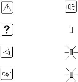
Pictograms
Document
Danger, these instruction are |
Audio signal. |
imperative. |
|
Information, advice, help. |
LED off |
Visual indication |
LED flashing |
Action |
LED on |
34020846EN/AD - Page 4

Environment
APC by Schneider Electric has implemented an environmental-protection policy.
Products are developed according to an eco-design approach.
Substances
This product does not contain CFCs, HCFCs or asbestos.
Packing
To improve waste treatment and facilitate recycling, separate the various packing components.
The cardboard we use comprises over 30% of recycled cardboard. |
|
|
|
|
Sacks and bags are made of polyethylene. |
|
|
|
|
Packing materials are recyclable and bear the appropriate identification symbol |
. |
|
|
|
|
|
|
|
|
Materials |
Abbreviation |
Number |
|
|
|
|
in the symbol |
|
|
|
|
|
|
|
Polyethylene terephthalate |
PET |
01 |
|
|
|
|
|
|
|
High-density polyethylene |
HDPE |
02 |
|
|
|
|
|
|
|
Polyvinyl chloride |
PVC |
03 |
|
|
|
|
|
|
|
Low-density polyethylene |
LDPE |
04 |
|
|
|
|
|
|
|
Polypropylene |
PP |
05 |
|
|
|
|
|
|
|
Polystyrene |
PS |
06 |
|
|
|
|
|
|
|
Follow all local regulations for the disposal of packing materials.
End of life
APC by Schneider Electric will process products at the end of their service life in compliance with local regulations. APC by Schneider Electric works with companies in charge of collecting and eliminating our products at the end of their service life.
Product
The product is made up of recyclable materials.
Dismantling and destruction must take place in compliance with all local regulations concerning waste.
At the end of its service life, the product must be transported to a processing centre for electrical and electronic waste. Make the product unusable by cutting the internal supply cables.
Battery
The product contains lead-acid batteries that must be processed according to applicable local regulations concerning batteries.
The battery may be removed to comply with regulations and in view of correct disposal. The "Material Safety Data Sheets" (MSDS) for the batteries are available on our web site*.
(*) For more information or to contact the Product Environmental manager, use the "Environmental Form" on the site: http://environment.apc.com
34020846EN/AD - Page 5
Contents
1. Installation |
|
1.1 Possible installations ......................................................................................................................... |
10 |
Single or modular UPS alone ............................................................................................................. |
10 |
Parallel UPS systems ......................................................................................................................... |
10 |
Modular UPSs in parallel ........................................................................................................... |
10 |
Modular UPSs in parallel with external bypass cabinet ............................................................. |
10 |
Parallel UPSs with SSC (static-switch cabinet) ......................................................................... |
11 |
Parallel UPS with SSC and SSC maintenance cabinet ............................................................ |
11 |
UPS set up as a frequency converter ................................................................................................. |
12 |
Single UPS ................................................................................................................................ |
12 |
Parallel UPS systems ................................................................................................................ |
12 |
1.2 Layout .................................................................................................................................................. |
13 |
Dimensions ......................................................................................................................................... |
13 |
Weights .............................................................................................................................................. |
13 |
Floor mounting ................................................................................................................................... |
14 |
UPS cabinets ........................................................................................................................... |
14 |
SSC ........................................................................................................................................... |
14 |
External bypass or SSC maintenance cabinets ........................................................................ |
15 |
Auxiliary cabinets (empty) ........................................................................................................ |
16 |
Backfeed cabinet ....................................................................................................................... |
16 |
Position in room .................................................................................................................................. |
17 |
UPS cabinets ............................................................................................................................ |
17 |
SSCs ......................................................................................................................................... |
17 |
External bypass cabinets .......................................................................................................... |
17 |
Battery / auxiliary cabinets ........................................................................................................ |
17 |
Ventilation ........................................................................................................................................... |
18 |
UPS cabinets ............................................................................................................................ |
18 |
SSC cabinets ............................................................................................................................ |
18 |
1.3 Prerequisites ....................................................................................................................................... |
19 |
UPS currents ...................................................................................................................................... |
19 |
Recommended upstream protection .................................................................................................. |
19 |
Normal AC source ................................................................................................................... |
19 |
Bypass AC source ................................................................................................................... |
19 |
Recommended maximum downstream protection ............................................................................ |
20 |
Battery protection ............................................................................................................................... |
20 |
Recommended residual-current protection ........................................................................................ |
20 |
Characteristics of the connection terminals ........................................................................................ |
21 |
UPS cabinets ............................................................................................................................ |
21 |
SSCs, SSC maintenance, External bypass cabinets ................................................................ |
21 |
Power cables for single UPSs ............................................................................................................ |
21 |
Power cables for parallel UPSs .......................................................................................................... |
22 |
Normal AC line and battery ....................................................................................................... |
22 |
Bypass AC line and load ........................................................................................................... |
22 |
1.4 System earthing arrangements ......................................................................................................... |
24 |
Single UPS system ............................................................................................................................. |
24 |
TNS upstream, TNS downstream ............................................................................................. |
24 |
TNC upstream, TNC, TNS or TT downstream installation ........................................................ |
25 |
IT upstream, IT downstream ..................................................................................................... |
25 |
Parallel UPSs systems ....................................................................................................................... |
25 |
1.5 Adapting the cabinet according to the neutral point connection .................................................. |
26 |
UPS cabinet ....................................................................................................................................... |
26 |
34020846EN/AD - Page 6
|
Contents |
SSC cabinet or external bypass cabinet ............................................................................................ |
26 |
1.6 Connecting the power cables ........................................................................................................... |
27 |
Single or modular UPS cabinet .......................................................................................................... |
27 |
250 to 400 kVA ......................................................................................................................... |
27 |
500 kVA .................................................................................................................................... |
28 |
Frequency-converter cabinet ............................................................................................................. |
29 |
250 to 400 kVA ......................................................................................................................... |
29 |
500 kVA .................................................................................................................................... |
30 |
Parallel UPS cabinet .......................................................................................................................... |
31 |
250 to 400 kVA ......................................................................................................................... |
31 |
500 kVA .................................................................................................................................... |
32 |
SSC cabinet ....................................................................................................................................... |
33 |
800 kVA .................................................................................................................................... |
33 |
1200 kVA .................................................................................................................................. |
34 |
2000 kVA .................................................................................................................................. |
35 |
2000 kVA light ........................................................................................................................... |
37 |
External bypass cabinet ..................................................................................................................... |
39 |
800 kVA .................................................................................................................................... |
39 |
1200 kVA .................................................................................................................................. |
40 |
2000 kVA .................................................................................................................................. |
41 |
SSC maintenance cabinet ................................................................................................................. |
42 |
800 and 1200 kVA .................................................................................................................... |
42 |
2000 kVA .................................................................................................................................. |
43 |
1.7 Connecting cabinet ECPs (exposed conductive parts) ................................................................. |
44 |
Interconnect the earths and tie down the wires ................................................................................. |
44 |
1.8 Connecting the synchronization module ........................................................................................ |
44 |
1.9 Connect the backfeed option ........................................................................................................... |
45 |
Block diagram .................................................................................................................................... |
45 |
Connect the power cables ................................................................................................................. |
45 |
1.10 Connecting the control-wire cables ............................................................................................... |
46 |
Connecting a modular UPS or frequency converter alone. ............................................................... |
46 |
Connecting the UPS units in parallel ................................................................................................. |
47 |
Connecting the modular UPS units in parallel .......................................................................... |
47 |
Connecting the modular UPSs with the external bypass .......................................................... |
48 |
Connecting parallel UPSs with SSC (static-switch cabinet) ..................................................... |
49 |
Connect the components specific to the 2000 kVA light SSC .................................................. |
50 |
Connect the SSC maintenance cabinet .................................................................................... |
50 |
Connecting the EPO function ............................................................................................................ |
51 |
Connecting the dry-contact communication card ............................................................................... |
52 |
1.11 Assembling and connecting the external battery cabinet ........................................................... |
53 |
Assembling the empty battery cabinet ............................................................................................... |
53 |
Mounting the battery circuit-breaker kit ................................................................................... |
53 |
Mounting the shelves ................................................................................................................ |
53 |
Connecting the power cables ............................................................................................................ |
54 |
Connecting the control-wire cables .................................................................................................... |
55 |
Connecting the battery circuit breaker ...................................................................................... |
55 |
Connecting the battery temperature sensor ............................................................................. |
56 |
2. Appendices
34020846EN/AD - Page 7
Contents
2.1 Assembling 2000 kVA SSCs .............................................................................................................. |
58 |
|
2.2 |
IP 32 option ......................................................................................................................................... |
58 |
2.3 |
Electrical characteristics ................................................................................................................... |
59 |
|
Selection of protection devices ........................................................................................................... |
59 |
|
Permissible UPS overloads as a function of time ............................................................................... |
60 |
2.4 General characteristics of MGE TM Galaxy TM 7000 UPSs ........................................................... |
61 |
|
|
Battery characteristics ........................................................................................................................ |
62 |
2.5 |
Glossary .............................................................................................................................................. |
63 |
34020846EN/AD - Page 8
Contents
34020846EN/AD - Page 9
1. Installation
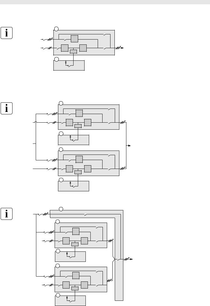
1.1 Possible installations
Single or modular UPS alone
Bypass AC
Normal AC
1 |
|
|
|
|
|
|
|
|
|
Q3BP |
|
|
Q4S |
D |
|
|
|
Q1 |
A |
|
B |
Q5N |
Load |
|
|
|
|||
|
|
|
C |
|
|
2 |
– |
|
|
|
|
|
QF1 |
|
|
||
|
+ |
|
|
||
UPS cabinet (1)
PFC rectifier module A Inverter module B Battery chopper C
Static-switch on AC bypass line D
Batteries (2)
Parallel UPS systems
(8 units maximum)
Modular UPSs in parallel
Bypass AC
Normal AC
Bypass AC
Normal AC
1 |
|
|
|
|
|
|
|
|
Q3BP |
|
Q4S |
D |
|
|
Q1 |
A |
|
B |
Q5N |
|
|
|
||
|
|
|
C |
|
2 |
– |
|
|
|
|
QF1 |
|
||
|
+ |
|
||
|
|
|
|
Load |
1 |
|
|
|
|
|
|
|
|
Q3BP |
|
Q4S |
D |
|
|
Q1 |
A |
|
B |
Q5N |
|
|
|
||
|
|
|
C |
|
2 |
– |
|
|
|
|
QF1 |
|
||
|
+ |
|
||
UPS cabinet (1)
PFC rectifier module A Inverter module B Battery chopper C
Static-switch on AC bypass line D
Batteries (2)
Modular UPSs in parallel with external bypass cabinet
Bypass AC |
3 |
|
Q3BP ext |
||
|
Bypass AC
Normal AC
Bypass AC
Normal AC
1 |
|
|
|
|
|
|
|
|
Q3BP |
|
Q4S |
D |
|
|
Q1 |
A |
|
B |
Q5N |
|
|
|
||
|
|
C |
|
|
2 |
– |
QF1 |
|
Q5N |
|
+ |
|
||
|
|
|
|
ext |
|
|
|
|
Load |
1 |
|
|
|
|
|
|
|
|
Q3BP |
|
Q4S |
D |
|
|
Q1 |
A |
|
B |
Q5N |
|
|
|
||
|
|
C |
|
|
2 |
– |
QF1 |
|
|
|
+ |
|
|
|
UPS cabinet (1)
PFC rectifier module A Inverter module B Battery chopper C
Static-switch on AC bypass line D
Batteries (2)
External bypass cabinet (3)
34020846EN/AD - Page 10
1. Installation
Possible installations >
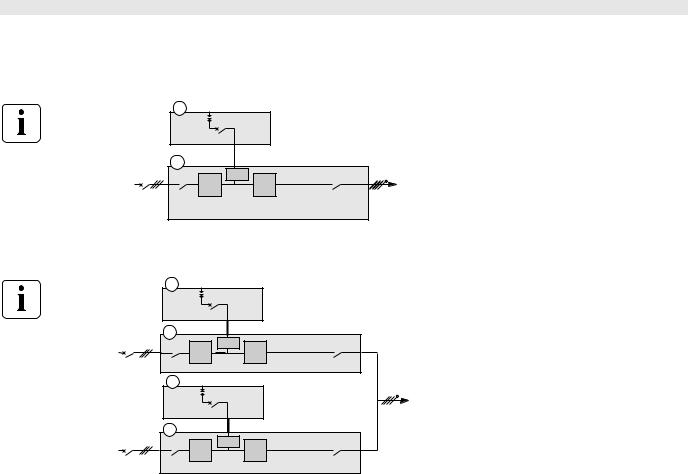
Parallel UPSs with SSC (static-switch cabinet)
|
3 |
|
|
|
|
|
|
|
|
|
|
|
|
|
Q3BP |
Bypass AC |
|
|
Q4S |
|
|
|
Q5N |
|
|
|
|
|
D |
||
|
|
|
|
|
|
Load |
|
|
1 |
|
|
|
|
|
|
Normal AC |
|
Q1 |
A |
|
|
B |
Q5N |
|
|
|
|
||||
|
|
|
|
|
|
||
|
|
|
|
|
C |
|
|
|
2 |
|
– |
|
|
+ |
- |
|
|
|
QF1 |
QF1 |
|||
|
|
|
+ |
||||
|
1 |
|
|
|
|
|
|
Normal AC |
|
Q1 |
A |
|
|
B |
Q5N |
|
|
|
|
||||
|
|
|
|
|
|
||
|
|
|
|
|
C |
|
|
|
2 |
|
– |
|
|
|
|
|
|
|
QF1 |
|
|
|
|
|
|
|
+ |
|
|
|
UPS1 cabinet (1)
PFC rectifier module A
Inverter module B
Battery chopper C
Batteries (2)
SSC (3)
Static-switch on AC bypass line D
Parallel UPS with SSC and SSC maintenance cabinet
|
3 |
|
|
|
|
|
|
|
|
|
|
|
|
|
|
Q3BP |
|
Bypass AC |
|
|
Q4S |
|
|
|
Q5N |
|
|
|
|
|
|
D |
Load |
||
|
|
|
|
|
|
|
||
|
|
|
|
|
|
|
4 |
|
|
|
|
|
|
|
|
QN |
QM |
|
1 |
|
|
|
|
|
|
|
Normal AC |
|
Q1 |
A |
|
|
B |
Q5N |
|
|
|
|
|
|
||||
|
|
|
|
|
|
|
||
|
|
|
|
|
C |
|
|
|
|
2 |
|
– |
|
|
+ |
- |
|
|
|
|
QF1 |
QF1 |
|
|||
|
|
|
+ |
|
||||
|
1 |
|
|
|
|
|
|
|
Normal AC |
|
Q1 |
A |
|
|
B |
Q5N |
|
|
|
|
|
|
||||
|
|
|
|
|
|
|
||
|
|
|
|
|
C |
|
|
|
|
2 |
|
– |
|
|
|
|
|
|
|
|
QF1 |
|
|
|
|
|
|
|
|
+ |
|
|
|
|
UPS 1 cabinet (1)
PFC module A
Inverter module B
Battery chopper C
Batteries (2)
SSC (3)
Backup static switch module D
SSC maintenance cabinet (4)
34020846EN/AD - Page 11
1. Installation
Possible installations >
UPS set up as a frequency converter
(with or without battery, maximum eight units)
Single UPS
|
2 |
– |
|
|
|
|
|
QF1 QF1 + – |
|
|
|
|
|
+ |
|
|
|
|
1 |
|
|
|
|
Normal AC |
Q1 |
|
C |
Q5N |
|
|
A |
B |
Load |
||
|
|
|
UPS cabinet (1)
PFC rectifier module A Inverter module B Battery chopper C
Batteries (2)
Parallel UPS systems |
|
|
|
|
|
|
||
|
2 |
– |
|
|
|
|
UPS cabinet (1) |
|
|
|
|
|
|
PFC rectifier module A |
|||
|
|
QF1 |
|
|
|
|||
|
|
+ |
|
|
|
|||
|
|
|
|
|
|
|
Inverter module B |
|
|
1 |
|
|
|
|
|
Battery chopper C |
|
Normal AC |
|
C |
|
|
|
|
||
Q1 |
A |
B |
Q5N |
Load |
Batteries (2) |
|||
|
|
|||||||
|
|
|
|
|||||
|
2 |
– |
|
|
|
|
|
|
|
|
QF1 |
|
|
|
|
||
|
|
+ |
|
|
|
|
||
|
1 |
|
|
|
|
|
|
|
Normal AC |
Q1 |
A |
C |
B |
Q5N |
|
|
|
|
|
|
|
|
|
|||
34020846EN/AD - Page 12
1. Installation
Layout >
1.2 Layout
Dimensions
|
|
Overall dimensions H x W x D in mm |
|
|
|
|
|
|
|
Unpacked cabinet |
On pallet cabinet |
|
|
|
|
|
UPS cabinets in kVA |
|
|
|
|
|
|
|
250 - 300 |
1900 x 1412 x 855 |
2027 x 1525 x 970 |
|
|
|
|
|
400 |
1900 x 1412 x 855 |
2027 x 1525 x 970 |
|
|
|
|
|
500 |
1900 x 1812 x 855 |
2027 x 1925 x 970 |
|
|
|
|
|
|
|
|
|
SSCs in kVA |
|
|
|
|
|
|
|
800 |
1900 x 1012 x 855 |
2027 x 1125 x 970 |
|
|
|
|
|
1200 |
1900 x 1412 x 855 |
2027 x 1525 x 970 |
|
|
|
|
|
2000 |
1900 x 1412 x 855 |
2027 x 1525 x 970 |
|
|
1900 x 1012 x 855 |
2027 x 1125 x 970 |
|
|
|
|
|
2000 light |
1900 x 1012 x 855 |
2027 x 1125 x 970 |
|
|
|
|
|
External bypass or SSC maintenance cabinets in kVA |
||
|
|
|
|
|
800 |
1900 x 1012 x 855 |
2027 x 1125 x 970 |
|
|
|
|
|
1200 |
1900 x 1412 x 855 |
2027 x 1525 x 970 |
|
|
|
|
|
2000 |
1900 x 1412 x 855 |
2027 x 1525 x 970 |
|
|
|
|
|
Battery /auxiliary cabinets (mm width) |
|
|
|
|
|
|
|
400 |
1900 x 412 x 855 |
2027 x 959 x 970 |
|
|
|
|
|
700 |
1900 x 712 x 855 |
2027 x 825 x 970 |
|
|
|
|
|
1000 |
1900 x 1012 x 855 |
2027 x 1125 x 970 |
|
|
|
|
|
1400 |
1900 x 1412 x 855 |
2027 x 1525 x 970 |
|
|
|
|
Weights
Weight values are purely indicative.
See the packing labels for the precise weight of the equipment.
UPS cabinets
Power rating in kVA |
250 |
300 |
400 |
500 |
|
|
|
|
|
Max. weight in kg |
960 |
960 |
1110 |
1470 |
|
|
|
|
|
External bypass cabinets or SSC maintenance cabinets
Power rating in kVA |
800 |
1200 |
2000 |
|
|
|
|
Max. weight in kg |
340 |
450 |
700 |
|
|
|
|
SSC
Power rating in kVA |
800 |
1200 |
2000 |
2000 light |
|
|
|
|
|
Max. weight in kg |
450 |
720 |
1430 |
600 |
|
|
|
|
|
Auxiliary cabinets (empty) |
|
|
|
|
|
|
|
|
|
Power rating in kVA |
400 |
700 |
1000 |
1400 |
|
|
|
|
|
Max. weight in kg |
90 |
135 |
150 |
200 |
|
|
|
|
|
For more information on the weight of your system, see the Transport/storage/handling manual (doc. no. 34020840).
34020846EN/AD - Page 13
1. Installation
Layout >
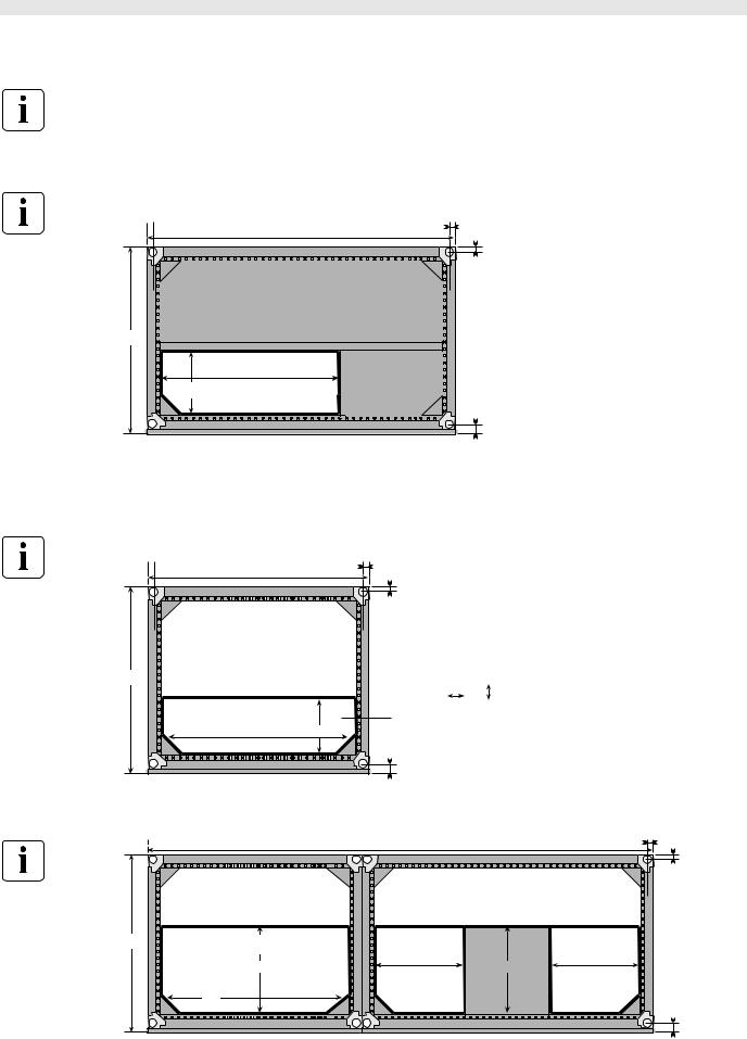
Floor mounting
Normal or false floor.
Dimensions are indicated in millimeters.
UPS cabinets
Top view
250/300/400 kVA : 1412 |
33.5 |
|
|
||
|
500 kVA : 1812 |
|
|
|
33.5 |
855 |
|
|
|
250/300/400 kVA : 760 |
|
|
500 kVA : 1280 |
|
290 |
Cable-running zone |
|
|
|
69.5 |
|
Front |
|
The four feet of the cabinet are cylindrical, 60 mm in diameter.
The measurements opposite include the cabinet cover panels and the door.
Max. load on floor per square cm for the feet
UPS cabinet |
kg/cm2 |
in kVA |
|
|
|
250 |
9 |
300 |
9 |
400 |
10 |
500 |
13 |
|
|
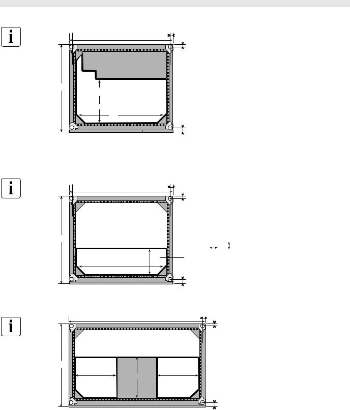
SSC
800 and 1200 kVA
Top view
|
33.5 |
800 kVA |
: 1012 |
1200 kVA |
: 1412 |
|
33.5 |
855 |
|
|
800 kVA |
|
1200 kVA |
Cable-running zone |
|
|
69.5 |
Front |
|
:1012 x 260
:1280 x 260
Max. load on floor per square cm for the feet
SSCs in kVA |
kg/cm2 |
|
|
800 |
4 |
1200 |
8 |
2000 |
15 |
2000 light |
6 |
|
|
2000 kVA
Top view |
|
2474 |
|
33.5 |
|
|
|
|
33.5 |
855 |
Cable-running zone |
|
|
|
|
415 |
415 |
415 |
385 |
|
Cable-running |
Cable-running |
||
|
|
|
||
|
870 |
zone |
|
zone |
|
|
|
|
|
|
|
|
|
69.5 |
|
|
Front |
|
|
34020846EN/AD - Page 14
1. Installation
Layout > Floor mounting
2000 kVA light
Top view |
33.5 |
|
1012 |
|
33.5 |
855 |
Cable-running zone |
|
|
|
430 |
|
870 |
|
69.5 |
|
Front |
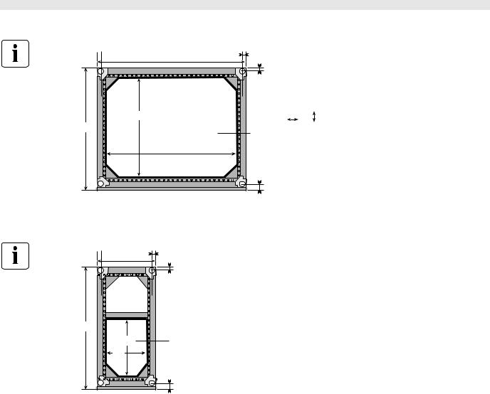
External bypass or SSC maintenance cabinets
800 and 1200 kVA
Top view |
|
33.5 |
|
800 kVA |
: 1012 |
|
|
1200 kVA |
: 1412 |
|
|
|
|
33.5 |
|
855 |
|
|
|
|
|
800 kVA |
: 1012 x 260 |
|
|
1200 kVA |
: 1280 x 260 |
Cable-running zone |
|
|
|
|
|
69.5 |
|
Front |
|
|
|
2000 kVA |
|
|
|
Top view |
1412 |
|
33.5 |
|
|
|
33. |
855 |
|
|
|
415 |
415 |
385 |
|
Cable-running |
Cable-running |
|
|
|
|
||
zone |
|
zone |
|
|
|
|
69. |
|
Front |
|
|
Max. load on floor per square cm for the feet
External bypass or |
kg/cm2 |
SSC maintenance |
|
cabinet in kVA |
|
|
|
800 |
4 |
1200 |
5 |
2000 |
8 |
|
|
34020846EN/AD - Page 15
1. Installation
Layout > Floor mounting
Auxiliary cabinets (empty)
Top view |
400 |
: 412 |
33.5 |
|
|
|
700 |
: 712 |
|
|
|
|
1000 : 1012 |
|
|
|
|
|
1400 : 1412 |
|
|
|
|
|
|
|
33.5 |
|
|
|
Cable-running zone |
|
|
|
|
855 |
|
|
400 mm |
: 278 |
x 679 |
|
|
|
700 mm |
: 578 |
x 679 |
|
|
|
1000 mm |
: 878 |
x 679 |
|
|
|
1400 mm |
: 1278 x 679 |
|
|
|
|
69.5 |
|
|
|
|
Front |
|
|
|
Backfeed cabinet
Top view |
33.5 |
412 |
|
|
33.5 |
855 |
|
382 |
Cable-running zone |
281 |
|
|
69.5 |
Front |
|
Max. load on floor per square cm for the feet
Auxiliary |
kg/cm2 |
cabinet in |
|
mm |
|
|
|
400 |
0,9 |
700 |
1,2 |
1000 |
1,3 |
1400 |
1,8 |
|
|
34020846EN/AD - Page 16
1. Installation
Layout >
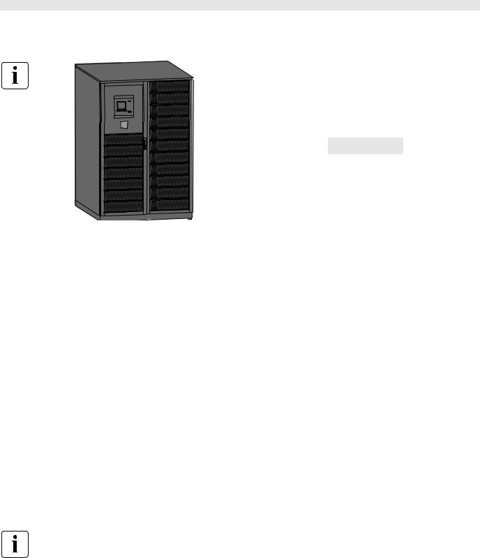
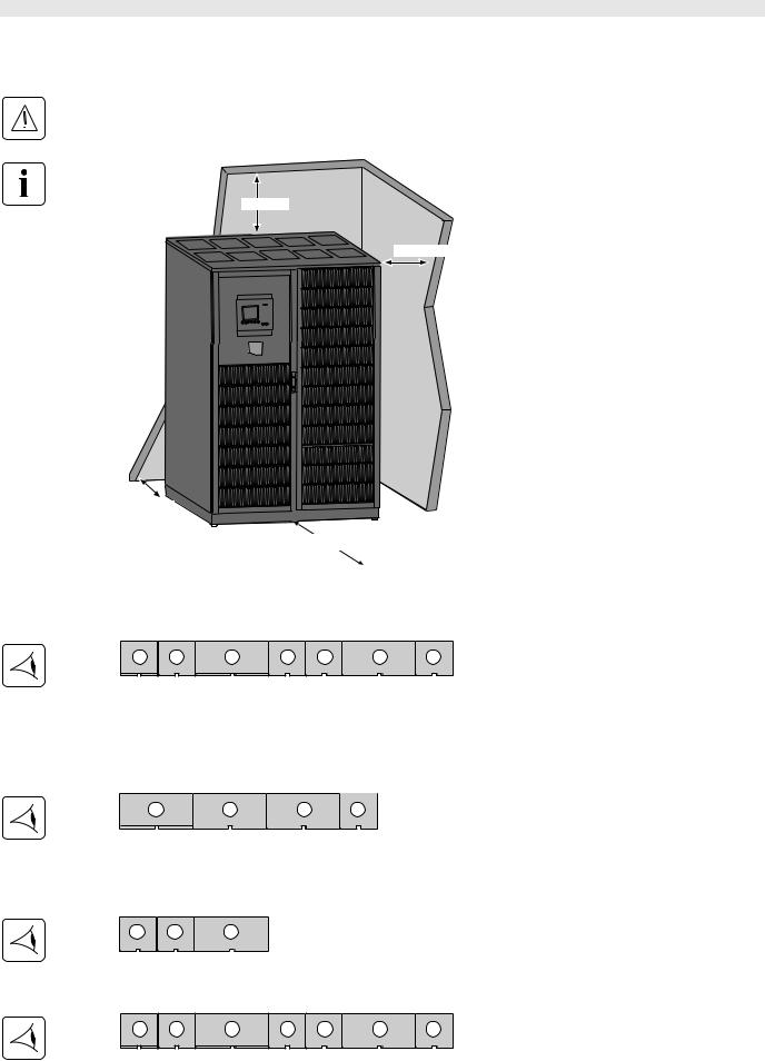
Position in room
UPS cabinets
The UPS must be installed in a room with restricted access (qualified personnel only).
|
To ensure correct ventilation, leave nothing |
|
on top of the UPS. |
>500 mm |
Leave one meter of free space in front of the |
|
UPS for door opening. |
>600 mm |
The cabinet rests on four cylindrical feet, 60 |
|
mm in diameter, positioned in the four corners |
|
of the cabinet to spread the weight. |
|
If 500 mm of free space is not maintained |
|
above the UPS, abnormal temperature rise |
|
may occur. |
|
The UPS can operate correctly back to the |
|
wall, but it is preferable to leave some space |
|
for easier maintenance. |
|
The distance between the bottom panel and |
>300 mm |
the floor must be less than 10 mm. |
|
|
>600 mm |
|
|
>1000 mm |
SSCs
Layout example for an SSC with two parallel UPS units
|
|
|
|
|
|
|
Auxiliary cabinet 2 (1) |
1 |
2 |
3 |
4 |
5 |
6 |
7 |
Battery cabinet 2 (2) |
|
|
|
|
|
|
|
UPS2 cabinet (3) |
|
|
|
|
|
|
|
Auxiliary cabinet 1 (4) |
|
|
|
|
|
|
|
Battery cabinet 1(5) |
|
|
|
|
|
|
|
UPS1 cabinet (6) |
|
|
|
|
|
|
|
SSC (7) |
External bypass cabinets
Layout example for an external bypass cabinet with three UPS units
|
|
|
|
UPS1 cabinet (1) |
1 |
2 |
3 |
4 |
UPS2 cabinet (2) |
|
|
|
|
UPS3 cabinet (3) |
|
|
|
|
External bypass cabinet (4) |
Battery / auxiliary cabinets
Layout example for two battery cabinets with one UPS unit
|
|
|
Battery cabinet 1 (1) |
1 |
2 |
3 |
Battery cabinet 2 (2) |
|
|
|
UPS cabinet (3) |
Layout example for two battery cabinets and two auxiliary cabinets in a parallel system with an SSC
|
|
|
|
|
|
|
Auxiliary cabinet 2 (1) |
1 |
2 |
3 |
4 |
5 |
6 |
7 |
Battery cabinet 2 (2) |
|
|
|
|
|
|
|
UPS2 cabinet (3) |
|
|
|
|
|
|
|
Auxiliary cabinet 1 (4) |
|
|
|
|
|
|
|
Battery cabinet 1 (5) |
|
|
|
|
|
|
|
UPS1 cabinet (6) |
|
|
|
|
|
|
|
SSC (7) |
34020846EN/AD - Page 17
1. Installation
Layout >
Ventilation
The optimum operating-temperature range is 20 to 25°C.
An operating temperature of 35°C is possible, but battery life will be reduced.
Size the ventilation system taking into account the values in the table below.
UPS cabinets
Power rating in kVA |
|
250 |
300 |
400 |
500 |
|
|
|
|
|
|
|
|
Air flow (m³/h) |
|
6000 |
6000 |
6000 |
8300 |
|
|
|
|
|
|
|
|
Heat losses to be |
kW |
14.3 |
17.2 |
22.9 |
27.2 |
|
evacuated at Pn |
|
|
|
|
|
|
Cal./s |
3418 |
4111 |
5473 |
6501 |
||
|
||||||
|
|
|
|
|
|
SSC cabinets
Power rating in kVA |
800 |
1200 |
2000 |
||
|
|
|
|
|
|
Air flow (m³/h) |
1000 |
Natural |
Natural |
||
|
|
|
|
||
Heat losses to be |
kW |
3.7 |
< 1 |
< 1.5 |
|
evacuated at Pn |
|
|
|
|
|
Cal./s |
884 |
< 240 |
< 360 |
||
|
|||||
|
|
|
|
|
|
Pn = rated power, for other values please consult the after-sales support or the local office.
34020846EN/AD - Page 18

1. Installation
Prerequisites >
1.3 Prerequisites
UPS currents
UPS cabinets in kVA |
I rated of Normal |
I rated of Bypass |
I rated of load |
I battery in A |
|
AC in A |
AC in A |
in A |
|
|
|
|
|
|
250 |
351 |
361 |
361 |
490 |
|
|
|
|
|
300 |
420 |
433 |
433 |
588 |
|
|
|
|
|
400 |
558 |
577 |
577 |
784 |
|
|
|
|
|
500 |
700 |
722 |
722 |
980 |
|
|
|
|
|
The table above is for 400 V interphase voltages and a load with a power factor of 0.9.
For other voltages (380 or 415 V), the current values must be multiplied by 1.05 and 0.96 respectively.
The battery current is an average current for a battery voltage of 488 V (44 blocks at 1.85 V/cell each), at Pn with a power factor of 0.9.
Recommended upstream protection
Normal AC source
Stick a label with the following text on each upstream circuit breaker / switch-disconnector: "Isolate Uninterruptible Power Supply (UPS) before working on this circuit".
Selection of protective devices is determined by the maximum continuous current (at 380 V). Protection ratings are calculated for the maximum continuous current (at 380V).
UPS cabinets in kVA |
CB / switch-disconnector |
Trip unit |
|
|
|
250 |
NS 630N 3P * |
STR 23 SE |
|
|
|
300 |
NS 630N 3P * |
STR 23 SE |
|
|
|
400 |
NS 800N 3P * |
Micrologic 2.0 |
|
|
|
500 |
NS 800N 3P * |
Micrologic 5.0 |
|
|
|
The circuit breakers / switch-disconnectors recommended above respect the requirements for discrimination with the UPS fuses.
Depending on the installation, the CB/SD may be replaced by a CB/SD with a higher breaking capacity.
* For short-circuit currents > 40 kA, use a CB/SD with a higher breaking capacity (type L or H).
Bypass AC source
Stick a label with the following text on each upstream circuit breaker / switch-disconnector: "Isolate Uninterruptible Power Supply (UPS) before working on this circuit".
Selection of protective devices is determined by the maximum continuous current (at 380 V). Protection ratings are calculated for the maximum continuous current (at 380V).
UPS cabinets in kVA |
Maximum permissible |
CB / switch- |
Trip unit |
|
current for 20 ms |
disconnector |
|
|
|
|
|
250 |
25 In |
NS 630N 4P * |
STR 23 SE |
|
|
|
|
300 |
21 In |
NS 630N 4P * |
STR 23 SE |
|
|
|
|
400 |
16 In |
NS 800N 4P * |
Micrologic 2.0 |
|
|
|
|
500 |
16 In |
NS 800N 4P * |
Micrologic 5.0 |
|
|
|
|
The circuit breakers / switch-disconnectors recommended above respect the requirements for discrimination with the UPS fuses.
Depending on the installation, the CB/SD may be replaced by a CB/SD with a higher breaking capacity.
* For short-circuit currents > 40 kA, use a CB/SD with a higher breaking capacity (type L or H).
34020846EN/AD - Page 19

1. Installation
Prerequisites >
Recommended maximum downstream protection
If these recommendations are not followed, a short-circuit on an output circuit can result in a break in power longer than 20 milliseconds on all the other output circuits.
UPS cabinets in kVA |
CB / switch- |
Trip unit |
|
disconnector |
|
|
|
|
250 |
NS 100N |
TM D 80 |
|
C120N |
C 80A |
|
C120N |
B 125A |
|
|
|
300 |
NS 100N |
TM D 80 |
|
C120N |
C 80A |
|
C120N |
B 125A |
|
|
|
400 |
NS 100N |
TM D 100 |
|
NG 125N |
C 125A |
|
C 125H |
C 125A |
|
|
|
500 |
C125N |
D 125A |
|
NS 160N |
TM 160D |
|
NG 125N |
D 125 |
|
|
|
Depending on the installation, the CB/SD may be replaced by a CB/SD with a higher breaking capacity.
These protective devices ensure discrimination for each circuit downstream of the UPS, with or without a bypass AC input.
Battery protection
UPS cabinets in kVA |
Battery backup time at |
Battery CB/switch-disconnector QF1 |
||
|
Pn |
|
|
|
|
|
|
|
|
|
|
Type |
Trip unit |
magnetic setting in A |
|
|
|
|
|
250 |
All |
NS630 DC |
MP1 |
1200 |
|
|
|
|
|
300 |
≤ 15 min. |
NS630 DC |
MP1 |
1200 |
|
> 15 min. |
C1251N DC |
P21 |
1600 |
|
|
|
|
|
400 |
≤ 5 min. |
NS630 DC |
MP1 |
1200 |
|
> 5 min. |
C1251N DC |
P21 |
1600 |
|
|
|
|
|
500 |
All |
C1251N DC |
P21 |
1600 |
|
|
|
|
|
Pn = rated power at a power factor of 0.9, for other values please consult the after-sales support or the local office.
See the necessary precautions during connection of circuit breakers / switch-disconnectors in the installation manual of the battery circuit-breaker enclosure, doc. no. 34021529.
Recommended residual-current protection
Requirements for residual-current protection.
For common normal and bypass AC inputs
- The same residual-current protection may be used for the two lines.
For separate normal and bypass AC inputs
-A transformer is required upstream of either the normal AC line or the bypass AC line.
-Equip each line with a circuit breaker or switch-disconnector with residual current protection.
See “System earthing arrangements”, page 24.
The recommended minimum residual current protection is 3A, provided the conditions defined in IEC364.4-41 are respected.
34020846EN/AD - Page 20
Loading...