


 Loading...
Installation and
Operation
G-Type Rack Power Filter
G5BLK
120V
15A

Contents
General Information ....................................................... |
1 |
Overview . . . . . . . . . . . . . . . . . . . . . . . . . . . . . . . . . . . . . . . . . . . . . . . . 1
Inventory . . . . . . . . . . . . . . . . . . . . . . . . . . . . . . . . . . . . . . . . . . . . . . . . 1
Safety . . . . . . . . . . . . . . . . . . . . . . . . . . . . . . . . . . . . . . . . . . . . . . . . . . 1
Components . . . . . . . . . . . . . . . . . . . . . . . . . . . . . . . . . . . . . . . . . . . . . 2
Installation ...................................................................... |
3 |
Install the Unit . . . . . . . . . . . . . . . . . . . . . . . . . . . . . . . . . . . . . . . . . . . 3
Connect A/C Power . . . . . . . . . . . . . . . . . . . . . . . . . . . . . . . . . . . . . . . 3
Operation ........................................................................ |
5 |
Display Interface . . . . . . . . . . . . . . . . . . . . . . . . . . . . . . . . . . . . . . . . . |
5 |
Configuration .................................................................. |
9 |
Troubleshooting .......................................................... |
10 |
Common problems and solutions . . . . . . . . . . . . . . . . . . . . . . . . . . 10 Contact APC APV Technical Support . . . . . . . . . . . . . . . . . . . . . . . 10
Specifications |
............................................................... 11 |
Warranty . . . . . . . . . . . . . . . . . . . . . . . . . . . . . . . . . . . . . . . . . . . . . . . |
11 |
Español ......................................................................... |
13 |
Français (Canada) ........................................................ |
25 |
APC A/V G-Type Rack Power Filter |
i |
ii |
APC A/V G-Type Rack Power Filter |
General Information
Overview
The APC® AV G-Type Rack Power Filter protects high-performance audio and video system equipment from damage due to power surges, spikes, and lightning strikes.
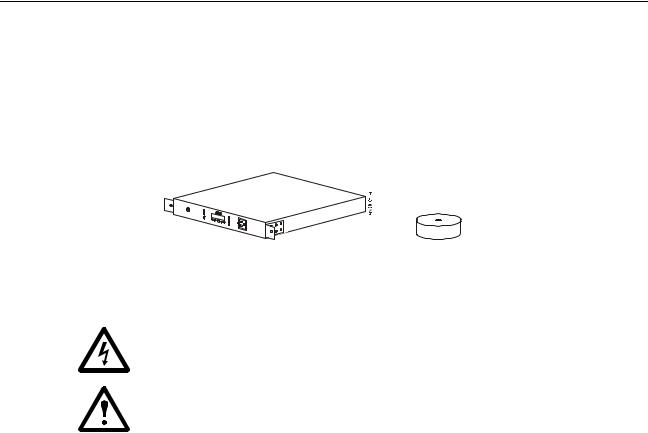
Inventory
Power conditioner (1) |
Stabilizing feet (4) |
Safety
•Electrical Hazard: For indoor use only.
•CAUTION - Do not install this device if there is not at least 10 meters (30 feet) or more of wire between the electrical outlet and the electrical service panel.
•Risk of electric shock. Do not plug into another relocatable power tap.
•Contains always on receptacles. To reduce the risk of electric shock, disconnect the unit from the power source before servicing the equipment.
•Overloading. Do not overload the wall outlet where this device is being connected. Do not overload this device. Ensure the total load to this device does not exceed that which is listed in the Specifications section of this manual.
•Power. Ensure this device is connected to a properly grounded AC power source. Further ensure the device is plugged into a source providing the required 120 Vac. Do not use a plug adapter which defeats the ground pin of the AC plug.
•Placement. Do not install this device on any unsteady surface. Do not install this device on any heat source.
•Water and Moisture. Do not use this product near any source of water, or in an environment where the relative humidity may exceed 95% (non-condensing)
•Polarization. This device has a polarized AC line plug having one grounding pin. This plug will only fit into the wall outlet in one orientation. This is a safety feature. Do not remove the round grounding pin.
•System Ground Terminal. The unit provides for the connection of grounding wires from all of your equipment to a central terminal lug. This ground connection eliminates ground loop problems; tie all component grounds to this screw to break any possible ground loops that can cause an audible noise.
•Servicing. There are no user-serviceable components within this device. Removal of the cover from this device may present a shock hazard, and/or void the warranty.
•Damage Requiring Service. If any type of damage occurs to this device, immediately disconnect it from the wall outlet. Notify APC Technical Support or Customer Service at once.
•Replacement Parts. There are no components within this device that can or should be removed/replaced unless it is by an APC-qualified technician.
APC A/V G-Type Rack Power Filter: General Information |
1 |
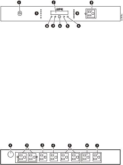
Components
Front view
Circuit breakerLCD Display
ALWAYS ON outlet
DOWN buttonUP button
Power buttonSETUP buttonSTATUS button
LED Indicators:
• POWER ON
• LINE OK
• PROTECTION
WORKING
• WIRING OK
• OVERLOAD
• DELAYS 1-4
• SWITCHED
• ALWAYS ON
Rear view
av005a
System Ground
ALWAYS ON outlets
SWITCHED outlet
DELAY 1 outletDELAY 2 outletsDELAY 3 outletDELAY 4 outlet
2 |
APC A/V G-Type Rack Power Filter: General Information |
Installation
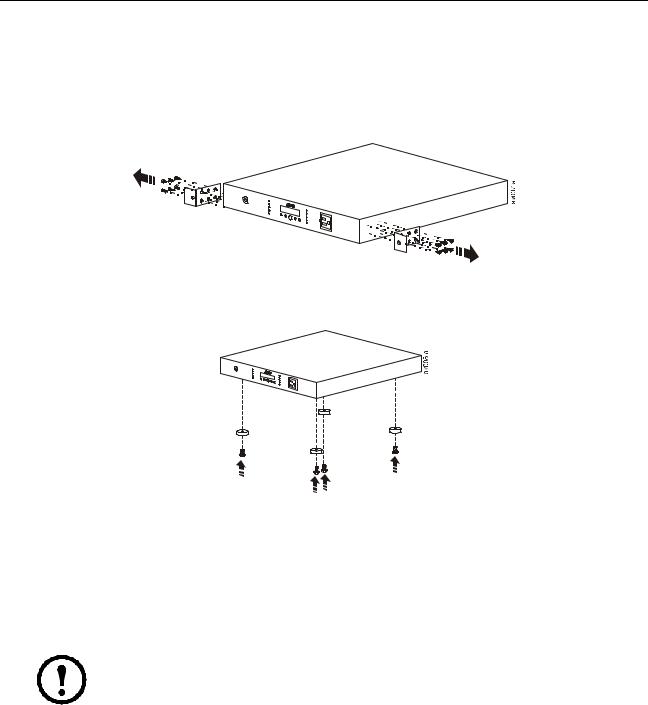
Install the Unit
Install the unit on a flat surface
The unit may be installed on any flat surface capable of supporting at least 27.3 kg (60 lbs).
Remove the mounting brackets.
Attach the stabilizing feet. Attach the stabilizing feet (included) to the bottom of the unit before placing it on a flat surface to avoid scratching the surface and to protect the unit.
Install the unit in a rack or enclosure
Use four screws to secure the mounting brackets to the rails in the rack or enclosure.
Connect A/C Power
Connect the unit to A/C power
Note: If the unit is connected to A/C power, the unit is actively monitoring input power, but is operating in Standby mode.
Use the A/C power cord to connect the unit to A/C power. If the unit is functioning properly, the display will illuminate.
Connect components to the unit
Before connecting components to the unit, determine which components will utilize the ALWAYS ON outlets, the SWITCHED outlet, and the DELAY outlets. Then, connect components to the outlets on the back panel of the unit.
APC A/V G-Type Rack Power Filter: Installation |
3 |
Always On outlets. The ALWAYS ON outlets supply power to the connected components, even if the unit is turned off. If A/C power is lost, and then re-applied to the unit, components connected to the ALWAYS ON outlets will turn on immediately, as power will be supplied to them immediately.
Switched outlet. The SWITCHED outlet supplies power to the connected equipment while the unit is on. If the unit shuts off, it will not supply power to equipment connected to the SWITCHED outlet. If A/C power is lost, and then re-applied to the unit, equipment connected to the SWITCHED outlet will turn on immediately.
Delay outlets. The unit has five delayed outlets. When the unit is turned on, power is immediately applied to the SWITCHED outlet (power was already being supplied to the ALWAYS ON outlets, even though the unit was off). Then, power is applied to each of the DELAYED outlets in sequence, DELAY 1 first, through DELAY 4.
When the unit is turned off, power is disconnected from the delayed outlets in reverse order.
Use the display interface to customize the delay times.
4 |
APC A/V G-Type Rack Power Filter: Installation |
Operation
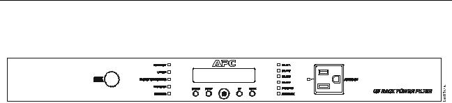
Display Interface
Using the display interface
Use the display interface on the front of the G5BLK to configure and operate the unit.
Power. Push to apply power to the unit or to shut off power to the unit.
Status. Push to display the current status of the unit, including the current input/output voltage.
Setup. Push to scroll through the setup menus.
Up/Down. Push to change values (Setup menu) and browse menu pages (Status menu).
Display interface LEDs
There are eleven LEDs on the display interface.
LED |
Illuminated |
Not Illuminated |
|
|
|
POWER ON |
The unit is supplied with utility |
There is no input utility power. |
|
power. |
|
|
|
|
LINE OK |
The utility power is within |
The input voltage from utility power is outside the |
|
acceptable range, 92 V to 140 V. |
acceptable range and the unit has disconnected from |
|
|
utility power to protect the connected equipment. |
|
|
|
PROTECTION |
The unit is protecting all connected |
The unit is not providing power protection. See |
WORKING |
equipment. |
Troubleshooting and contact APC Technical Support |
|
|
immediately. |
|
|
|
WIRING OK |
The unit is functioning properly. |
There is a problem with the building wiring. Contact a |
|
|
certified electrician. |
|
|
|
OVERLOAD |
The unit is overloaded. Disconnect |
The unit is functioning properly. |
|
some connected components. |
|
|
Contact APC Technical Support. |
|
|
|
|
DELAY 1 |
Power is being supplied to DELAY1. |
Power is not being supplied to DELAY1. |
|
|
|
DELAY 2 |
Power is being supplied to DELAY2. |
Power is not being supplied to DELAY2. |
|
|
|
DELAY 3 |
Power is being supplied to DELAY3. |
Power is not being supplied to DELAY3. |
|
|
|
DELAY 4 |
Power is being supplied to DELAY4. |
Power is not being supplied to DELAY4. |
|
|
|
SWITCHED |
Power is being supplied to the |
Power is not being supplied to the SWITCHED outlet. |
|
SWITCHED outlet. |
|
|
|
|
ALWAYS ON |
Power is being supplied to the |
Power is not being supplied to the ALWAYS ON outlets. |
|
ALWAYS ON outlets. |
See “Troubleshooting” on page 10 and contact APC |
|
|
Technical Support immediately. |
|
|
|
APC A/V G-Type Rack Power Filter: Operation |
5 |
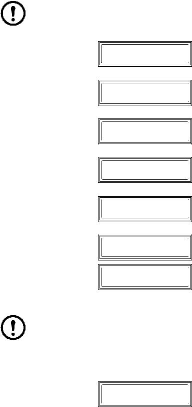
Status menu
Note: The menus shown in this manual are for reference only. Information displayed on the unit may be different than shown here.
Utility Source, Voltage and Frequency.
UTILITY SOURCE 120V 60Hz
Current and Percentage.
TOTAL OUTPUT 12A 80%
Contact Information.
1-888-8827228 WWW.APCAV.COM
Model and Serial Number.
G5 POWER FILTER
SN: AB1234567890
Firmware version.
FW REVISION: 860.M1.D
Recent Faults.
NO FAULT
FAULT CONDITION
Description
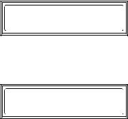
Setup menu
Note: The menus shown in this manual are for reference only. Information displayed on the unit may be different than shown here.
Use the Setup menus to configure the unit. There are nine setup menus. Push SETUP to scroll to the next menu.
LCD dimmer. Set the brightness of the display.
DISPLAY DIMMER:
NORMAL
6 |
APC A/V G-Type Rack Power Filter: Operation |
LED dimmer. Set the brightness of the LED.
LED DIMMER:
DIM1
Delay1. Select the number of seconds for the delay.
DELAY 1: 4SEC (1-60)
Delay2. Select the number of seconds for the delay.
DELAY 2: 4SEC (1-60)
Delay3. Select the number of seconds for the delay.
DELAY 3: 4SEC (1-60)
Delay4. Select the number of seconds for the delay.
DELAY 4: 4SEC (1-60)
Cut-Off Voltage. Select the maximum and minimum voltage. The unit will protect connected equipment from high and low voltages that are not safe for operation.
MAX UPPER VOLT: 140V (132-140)
MIN LOWER VOLT: 92V (92-100)
Language. Select the language for the display: English, French, or Spanish. Push SETUP to go to the
next screen, RESET TO DEFAULT.
MENU LANGUAGE:
ENGLISH
Restore default settings. Select YES or NO to restore the default settings.
RESET TO DEFAULT
YES
Lock the unit
The unit can be locked to prevent unwanted access. To lock or unlock the unit, push STATUS and DOWN for three seconds.
G5BLK LOCKED
APC A/V G-Type Rack Power Filter: Operation |
7 |
Save screen as default
To save a screen as the default, push STATUS for three seconds.
THIS SCREEN IS
SAVED AS DEFAULT
Shut down the unit
Push and hold the POWER button.
POWERING DOWN
8 |
APC A/V G-Type Rack Power Filter: Operation |

Configuration
Configure the unit
Select a language. Push the SETUP button until the Language menu is displayed. Select English, French, or Spanish.
Configure the brightness of the display. To alter the brightness of the LCD display screen, push SETUP one time and select a numerical value, one through seven.
Configure the sequence delay outlets
Configure the delay options so that the DELAY outlets apply power in sequence, instead of all at one time.
Push SETUP until the delay menu screen appears. Use the UP and DOWN buttons to change the number of seconds of delay. When finished, push SETUP again to move to the next delay screen.
View status of the unit
Push the STATUS button until the input source voltage and frequency screen appears.
Push the STATUS button to display the output current and percentage.
You can also view APC Technical Support contact information, the model and serial number of the unit, the firmware version, and the last three faults registered by the unit using the STATUS menus.
APC A/V G-Type Rack Power Filter: Configuration |
9 |
Loading...