


Back UPS BR1000G
Table of contents
 Loading...
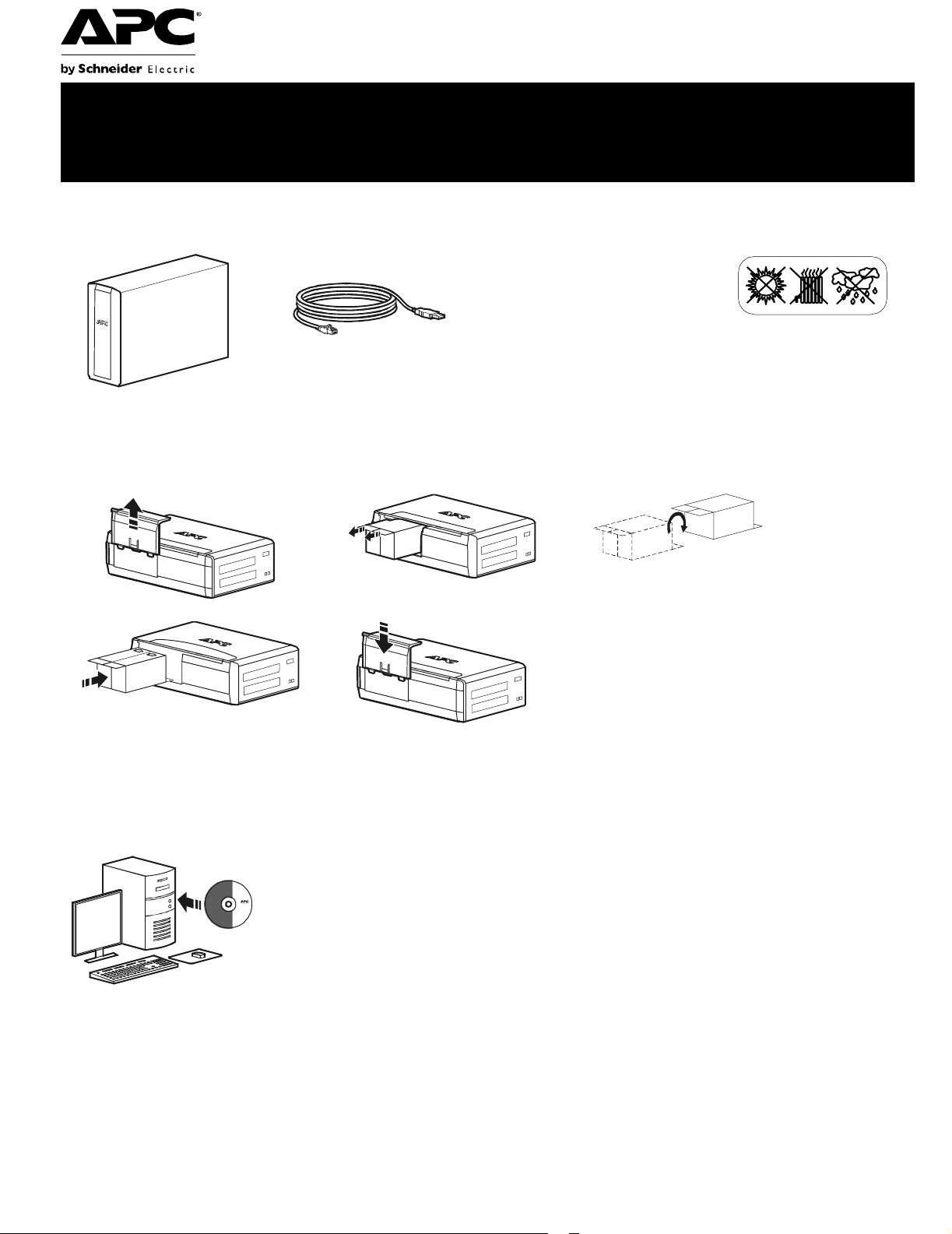
Back-UPS
®
Pro 1000 Installation and
Operation
Connect the battery
Install PowerChute
®
Personal Edition Software
APC PowerChute Personal Edition sof tware provides automatic file saving and shutdown of
your computer in the event of a power failure. Use the cable supplied with the Back-UPS to
connect the data port on the Back-UPS to the USB port on your computer. Place the CD into
your computer, and follow the on-screen instructions.
Inventory Safety
Do not install the Back-UPS in direct
sunlight, in excessive heat,
humidity, or in contact with fluids.
bu001b
bu055a
bu057a
bu059a
bu058a
bu060a
Back-UPS Pro 1000 Installation and Operation2
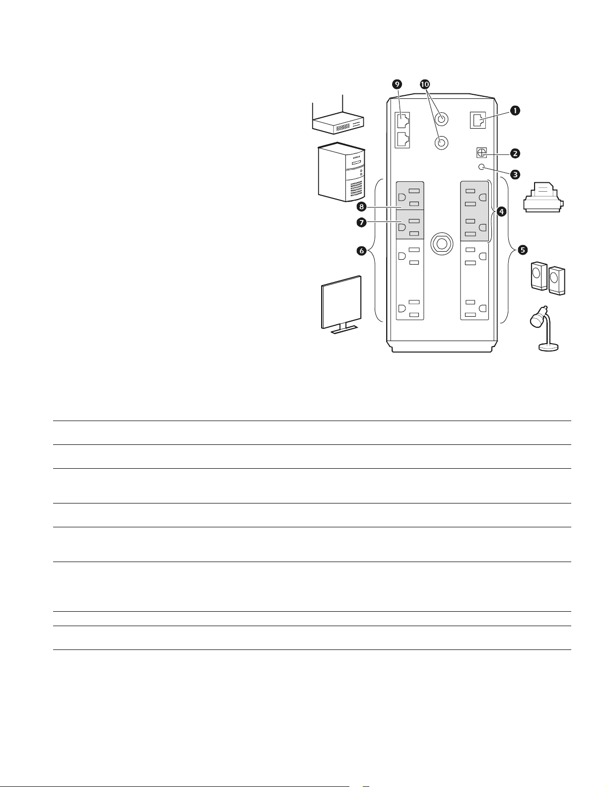
Connect the equipment
Battery Backup and Surge Protected outlets
When the Back-UPS is receiving input power, the
Battery Backup with Surge Protection outlets will
supply power to connected equipment. During a
power outage or other utility probl ems, the Batte ry
Backup outlets receive power for a limited time from
the Back-UPS.
Connect equipment such as printers, fax machines,
scanners, or other peripherals that do not need battery
backup power to the Surge Protect ion Only outlets.
These outlets provi de full-time prot ection from sur ges
even if the Back -UP S i s sw itche d OFF.
Master and Controlled outlets
T o conserve electricity, when the devic e connected to
Master Outlet goes into Sleep or Sta ndby mode, or
turns Off, the Controlled device(s) will shut down as
well, saving electricity.
Connect a master device, such as a des ktop computer
or audio/visual rec eiver to the Master outlet. Connec t
peripheral devices such as a printer, speakers, or a
scanner to the Controlled outlets.
USB and Serial Data port To use PowerChute Personal Edit ion, connect the supplied USB software cabl e or ser ial cable
(available separately).
Ground screw Connect the ground lead of additi onal s urge supp res sion devi ces suc h as n etwork an d dat a line
surge protectors.
Building Wiring Fault
indicator
If this indicator is il luminated, there is a problem with the wiring in the building. Contact an
electrician immedi ately and do not use the Back-UPS.
Surge Protected outlets,
controlled by the Master
outlet
These outlets are protected from electr ical surges, and will disconnect from utility power during
a power outage, or if the Mast er device goes into Sleep or St andby mode.
Surge Protected outlets These outlets provide full-time protection from surges, even if the Back-UPS is off. Connect
equipment such as printers and scanners that do not require bat tery backup protection.
Battery Backup outlets with
Surge Protection
During a power out age or other utility problems, the Battery Backup outlets receive power for a
limited time from the Bac k-UPS. Connect critical equipment such as desktop computer,
computer monitor, modem or other data sen sitive devices into these outle ts.
Battery Backup outlets with
Surge Protection, contr olled
by the Master outlet
These outlets will supply battery power to the connected equip me nt during a power outage.
Power will be disconnect ed to th ese outlets if the Master device goes into Sleep or Stan dby
mode. Connect equipment such as a computer monitor to these outlets.
Master outlet Connect the master device to this outlet, in most scenarios , this will be the main computer.
In & Out Ethernet surge-
protected ports
Use an Ethernet cable to connect a cable modem to the IN port, and connect a computer to the
O
UT port.
Co-axial ports w ith surge
protection
Connect a cable modem or other equipment with coaxial jacks.
bu126a

Back-UPS Pro 1000 Installation and O peration
3
Operation
Power-Saving Function
T o conserve electricity, configure the Back-UPS to recognize a Master devic e, such as a desktop
computer or an A/V receiver, and Controlled peripheral devices, such as a printer, speakers, or a scanner.
When the Master device goes into Sleep or Standby mode, or is switched OFF, the Controlled device(s)
will be switched off as well, saving electricity.
Enable the Power-Saving function. Press and hold MUTE and DISPLAY simultaneously for two se conds. The
Back-UPS will beep to indicate that the feature is enabled. The leaf icon on the display will illuminate.
Disable t he Power-Saving function. Press and hold MUTE and DISPLAY simultaneously for two seconds. The
Back-UPS will beep to indicate that the feature is disabled. The leaf icon on the display will darken.
Setting the threshold. The amount of power used by a device in Sleep or Standby mode varies between devices. It
may be necessary to adjust the threshold at which the Master outlet signals the Controlled outlets to shut down.
1. Ensure a master device is connected to the Master outlet. Put that device into Sleep or Standby mode, or turn it
OFF.
2. Press
DISPLAY and MUTE simultaneously and hold for six seconds, until the leaf icon flashes three times and the
Back-UPS beeps three times.
3. The Back-UPS will now recognize the thre shold level of the Master device and save it as the new threshold setting.
Power-Saving Display
The display interface can be configured to be continuously illuminated, or to save energy, it can be configured to
darken after a period of inactivity.
1. Full Tim e Mode: Press and hold
DISPLAY for two seconds. The display will illumina te and the Back-UPS will beep
to confirm the Full-Time mode.
2. Power-Saving Mode: Press a nd hold
DISPLAY for two seconds. The display will darken and the Back -UPS will
beep to confirm the Power-Saving mode. While in Power-Saving Mode, the display will illuminate if a button is
pressed, it then darkens after 60 seconds of no activity.
Unit sensitivity
Adjust the sensitivity of the Back-UPS to control when it will switch to battery power; the higher the sensitivity, the
more often the Back-UPS will switch to batter y power.
1. Ensure the Back-UPS is connected to utility power, but is OFF.
2. Press and hold the POWER button for six seconds. The LOAD CAPACITY bar will flash on and off, indicating that the
Back-UPS is in programming mode.
3. Press
POWER again to rotate through the menu options. Stop at selected sensitivity. The Back-UPS will beep to
confirm the selection.
Generator Sensitivity Default Sensitive Loads
Low sensitivity Medium sensitivity (Default) High sensitivity
78-142 Vac 88-139 Vac 88-136 Vac
Input voltage is extremely low or
high. (Not recom me nded for
computer loads. )
The Back-UPS frequently switches to
battery power.
The connected equipment is
sensitive to vol tage fluctuations.
Loading...