


AP9630
Table of contents
 Loading...
User’s Guide
UPS Network
Management Card 2
AP9630, AP9631

This manual is available in English on the APC Web site (www.apc.com).
Dieses Handbuch ist in Deutsch auf der APC Webseite (www.apc.com) verfügbar.
Este manual está disponible en español en la página web de APC (www.apc.com).
Ce manuel est disponible en français sur le site internet d’APC (www.apc.com).
Questo manuale è disponibile in italiano sul sito web di APC (www.apc.com).
Este manual está disponível em português no site da APC (www.apc.com).
Данное руководство на русском языке доступно на сайте APC (www.apc.com )
本マニュアル<各国の言語に対応する>はAPC ウェブサイト (www.apc.com)からダウ
ンロードできます
APC 웹싸이트 (www.apc.com) 에 한국어 매뉴얼 있습니다 .
在 APC 公司的网站上 (www.apc.com) 有本手册的中文版。
This manual is available in English on the enclosed CD.
Dieses Handbuch ist in Deutsch auf der beiliegenden CD-ROM verfügbar.
Este manual está disponible en español en el CD-ROM adjunto.
Ce manuel est disponible en français sur le CD-ROM ci-inclus.
Questo manuale è disponibile in italiano nel CD-ROM allegato.
。
Este manual está disponível em português no CD fornecido.
Данное руководство на русском языке имеется на прилагаемом компакт-диске.
本マニュアルの日本語版は同梱の CD-ROM からご覧になれます。
동봉된 CD 안에 한국어 매뉴얼이 있습니다 .
您可以从包含的 CD 上获得本手册的中文版本。

Contents
Introduction..................................................................... 1
Product Description . . . . . . . . . . . . . . . . . . . . . . . . . . . . . . . . . . . . . . .1
Features . . . . . . . . . . . . . . . . . . . . . . . . . . . . . . . . . . . . . . . . . . . . . . . . 1
IPv4 Initial setup . . . . . . . . . . . . . . . . . . . . . . . . . . . . . . . . . . . . . . . . . 2
IPv6 Initial setup . . . . . . . . . . . . . . . . . . . . . . . . . . . . . . . . . . . . . . . . . 2
Network management features . . . . . . . . . . . . . . . . . . . . . . . . . . . . . 2
Internal Management Features . . . . . . . . . . . . . . . . . . . . . . . . . . . . . . 3
Overview . . . . . . . . . . . . . . . . . . . . . . . . . . . . . . . . . . . . . . . . . . . . . . . 3
Access priority for logging on . . . . . . . . . . . . . . . . . . . . . . . . . . . . . . 3
Types of user accounts . . . . . . . . . . . . . . . . . . . . . . . . . . . . . . . . . . . 3
How to Recover from a Lost Password . . . . . . . . . . . . . . . . . . . . . . .4
Front Panel (AP9630) . . . . . . . . . . . . . . . . . . . . . . . . . . . . . . . . . . . . . .5
Features . . . . . . . . . . . . . . . . . . . . . . . . . . . . . . . . . . . . . . . . . . . . . . . . 5
Front Panel (AP9631) . . . . . . . . . . . . . . . . . . . . . . . . . . . . . . . . . . . . . .5
Features . . . . . . . . . . . . . . . . . . . . . . . . . . . . . . . . . . . . . . . . . . . . . . . . 5
LED Descriptions . . . . . . . . . . . . . . . . . . . . . . . . . . . . . . . . . . . . . . . . .6
Status LED . . . . . . . . . . . . . . . . . . . . . . . . . . . . . . . . . . . . . . . . . . . . . . 6
Link-RX/TX (10/100) LED . . . . . . . . . . . . . . . . . . . . . . . . . . . . . . . . . . 7
Watchdog Features. . . . . . . . . . . . . . . . . . . . . . . . . . . . . . . . . . . . . . . .7
Overview . . . . . . . . . . . . . . . . . . . . . . . . . . . . . . . . . . . . . . . . . . . . . . . 7
Network interface watchdog mechanism . . . . . . . . . . . . . . . . . . . . . 7
Resetting the network timer . . . . . . . . . . . . . . . . . . . . . . . . . . . . . . . 7
Command Line Interface................................................ 8
How To Log On . . . . . . . . . . . . . . . . . . . . . . . . . . . . . . . . . . . . . . . . . . .8
Overview . . . . . . . . . . . . . . . . . . . . . . . . . . . . . . . . . . . . . . . . . . . . . . . 8
Remote access to the command line interface . . . . . . . . . . . . . . . . 8
Local access to the command line interface . . . . . . . . . . . . . . . . . . 9
Main Screen. . . . . . . . . . . . . . . . . . . . . . . . . . . . . . . . . . . . . . . . . . . . . .9
Sample main screen . . . . . . . . . . . . . . . . . . . . . . . . . . . . . . . . . . . . . . 9
Information and status fields . . . . . . . . . . . . . . . . . . . . . . . . . . . . . . . 9
UPS Network Management Card 2 User’s Guide
i

How to Use the Command Line Interface. . . . . . . . . . . . . . . . . . . . . 11
Overview . . . . . . . . . . . . . . . . . . . . . . . . . . . . . . . . . . . . . . . . . . . . . . . 11
How to enter commands . . . . . . . . . . . . . . . . . . . . . . . . . . . . . . . . . . 11
Command syntax . . . . . . . . . . . . . . . . . . . . . . . . . . . . . . . . . . . . . . . . 11
Syntax examples . . . . . . . . . . . . . . . . . . . . . . . . . . . . . . . . . . . . . . . . 12
Command Response Codes . . . . . . . . . . . . . . . . . . . . . . . . . . . . . . . 12
Command Descriptions . . . . . . . . . . . . . . . . . . . . . . . . . . . . . . . . . . . 13
? . . . . . . . . . . . . . . . . . . . . . . . . . . . . . . . . . . . . . . . . . . . . . . . . . . . . . 13
about . . . . . . . . . . . . . . . . . . . . . . . . . . . . . . . . . . . . . . . . . . . . . . . . . . 13
alarmcount . . . . . . . . . . . . . . . . . . . . . . . . . . . . . . . . . . . . . . . . . . . . . 13
boot . . . . . . . . . . . . . . . . . . . . . . . . . . . . . . . . . . . . . . . . . . . . . . . . . . . 13
cd . . . . . . . . . . . . . . . . . . . . . . . . . . . . . . . . . . . . . . . . . . . . . . . . . . . . 14
console . . . . . . . . . . . . . . . . . . . . . . . . . . . . . . . . . . . . . . . . . . . . . . . . 14
date . . . . . . . . . . . . . . . . . . . . . . . . . . . . . . . . . . . . . . . . . . . . . . . . . . . 15
delete . . . . . . . . . . . . . . . . . . . . . . . . . . . . . . . . . . . . . . . . . . . . . . . . . 15
dir . . . . . . . . . . . . . . . . . . . . . . . . . . . . . . . . . . . . . . . . . . . . . . . . . . . . 16
dns . . . . . . . . . . . . . . . . . . . . . . . . . . . . . . . . . . . . . . . . . . . . . . . . . . . 16
eventlog . . . . . . . . . . . . . . . . . . . . . . . . . . . . . . . . . . . . . . . . . . . . . . . 16
exit . . . . . . . . . . . . . . . . . . . . . . . . . . . . . . . . . . . . . . . . . . . . . . . . . . . 16
format . . . . . . . . . . . . . . . . . . . . . . . . . . . . . . . . . . . . . . . . . . . . . . . . . 17
FTP . . . . . . . . . . . . . . . . . . . . . . . . . . . . . . . . . . . . . . . . . . . . . . . . . . . 17
help . . . . . . . . . . . . . . . . . . . . . . . . . . . . . . . . . . . . . . . . . . . . . . . . . . . 17
netstat . . . . . . . . . . . . . . . . . . . . . . . . . . . . . . . . . . . . . . . . . . . . . . . . . 17
View the status of the network and all active IPv4 and IPv6 addresses. 17
ntp . . . . . . . . . . . . . . . . . . . . . . . . . . . . . . . . . . . . . . . . . . . . . . . . . . . . 17
View and configure the network time protocol parame ters. . . . . . 17
ping . . . . . . . . . . . . . . . . . . . . . . . . . . . . . . . . . . . . . . . . . . . . . . . . . . . 18
portSpeed . . . . . . . . . . . . . . . . . . . . . . . . . . . . . . . . . . . . . . . . . . . . . . 18
prompt . . . . . . . . . . . . . . . . . . . . . . . . . . . . . . . . . . . . . . . . . . . . . . . . 18
quit . . . . . . . . . . . . . . . . . . . . . . . . . . . . . . . . . . . . . . . . . . . . . . . . . . . 19
radius . . . . . . . . . . . . . . . . . . . . . . . . . . . . . . . . . . . . . . . . . . . . . . . . . 19
reboot . . . . . . . . . . . . . . . . . . . . . . . . . . . . . . . . . . . . . . . . . . . . . . . . . 20
resetToDef . . . . . . . . . . . . . . . . . . . . . . . . . . . . . . . . . . . . . . . . . . . . . 20
snmp, snmp3 . . . . . . . . . . . . . . . . . . . . . . . . . . . . . . . . . . . . . . . . . . . 20
system . . . . . . . . . . . . . . . . . . . . . . . . . . . . . . . . . . . . . . . . . . . . . . . . 21
tcpip . . . . . . . . . . . . . . . . . . . . . . . . . . . . . . . . . . . . . . . . . . . . . . . . . . 21
tcpip6 . . . . . . . . . . . . . . . . . . . . . . . . . . . . . . . . . . . . . . . . . . . . . . . . . 21
uio . . . . . . . . . . . . . . . . . . . . . . . . . . . . . . . . . . . . . . . . . . . . . . . . . . . . 22
ups . . . . . . . . . . . . . . . . . . . . . . . . . . . . . . . . . . . . . . . . . . . . . . . . . . . 23
user . . . . . . . . . . . . . . . . . . . . . . . . . . . . . . . . . . . . . . . . . . . . . . . . . . . 24
web . . . . . . . . . . . . . . . . . . . . . . . . . . . . . . . . . . . . . . . . . . . . . . . . . . . 24
xferINI . . . . . . . . . . . . . . . . . . . . . . . . . . . . . . . . . . . . . . . . . . . . . . . . . 25
xferStatus . . . . . . . . . . . . . . . . . . . . . . . . . . . . . . . . . . . . . . . . . . . . . . 25
ii
UPS Network Management Card 2 User’s Guide

Web Interface.................................................................26
Introduction . . . . . . . . . . . . . . . . . . . . . . . . . . . . . . . . . . . . . . . . . . . . .26
Overview . . . . . . . . . . . . . . . . . . . . . . . . . . . . . . . . . . . . . . . . . . . . . . .26
Supported Web browsers . . . . . . . . . . . . . . . . . . . . . . . . . . . . . . . . .26
How to Log On. . . . . . . . . . . . . . . . . . . . . . . . . . . . . . . . . . . . . . . . . . .26
Overview . . . . . . . . . . . . . . . . . . . . . . . . . . . . . . . . . . . . . . . . . . . . . . .26
URL address formats . . . . . . . . . . . . . . . . . . . . . . . . . . . . . . . . . . . . . 27
Home Page. . . . . . . . . . . . . . . . . . . . . . . . . . . . . . . . . . . . . . . . . . . . . .28
Overview . . . . . . . . . . . . . . . . . . . . . . . . . . . . . . . . . . . . . . . . . . . . . . .28
Quick status icons . . . . . . . . . . . . . . . . . . . . . . . . . . . . . . . . . . . . . . . 28
Recent Device Events . . . . . . . . . . . . . . . . . . . . . . . . . . . . . . . . . . . . 28
How to Use the Tabs, Menus, and Links. . . . . . . . . . . . . . . . . . . . . .29
Tabs . . . . . . . . . . . . . . . . . . . . . . . . . . . . . . . . . . . . . . . . . . . . . . . . . . .29
Menus . . . . . . . . . . . . . . . . . . . . . . . . . . . . . . . . . . . . . . . . . . . . . . . . .29
Quick links . . . . . . . . . . . . . . . . . . . . . . . . . . . . . . . . . . . . . . . . . . . . .29
Monitor and Configure the UPS ...................................30
Overview Page. . . . . . . . . . . . . . . . . . . . . . . . . . . . . . . . . . . . . . . . . . .30
Operating state . . . . . . . . . . . . . . . . . . . . . . . . . . . . . . . . . . . . . . . . . .30
Quick Status . . . . . . . . . . . . . . . . . . . . . . . . . . . . . . . . . . . . . . . . . . . .30
Recent UPS Events . . . . . . . . . . . . . . . . . . . . . . . . . . . . . . . . . . . . . .31
Status Page . . . . . . . . . . . . . . . . . . . . . . . . . . . . . . . . . . . . . . . . . . . . .31
Status displayed for every UPS model . . . . . . . . . . . . . . . . . . . . . . 31
Model-specific status displayed . . . . . . . . . . . . . . . . . . . . . . . . . . . . 31
Control Page . . . . . . . . . . . . . . . . . . . . . . . . . . . . . . . . . . . . . . . . . . . .32
Synchronized Control Group guidelines . . . . . . . . . . . . . . . . . . . . .32
The synchronization process . . . . . . . . . . . . . . . . . . . . . . . . . . . . . . 32
Actions (for a single UPS and Synchronized Control G roups) . . .33
Configuration Pages . . . . . . . . . . . . . . . . . . . . . . . . . . . . . . . . . . . . . .35
The power option . . . . . . . . . . . . . . . . . . . . . . . . . . . . . . . . . . . . . . . . 35
The shutdown option . . . . . . . . . . . . . . . . . . . . . . . . . . . . . . . . . . . . .36
The general option . . . . . . . . . . . . . . . . . . . . . . . . . . . . . . . . . . . . . . . 37
The reset UPS defaults option . . . . . . . . . . . . . . . . . . . . . . . . . . . . .37
The self-test schedule option . . . . . . . . . . . . . . . . . . . . . . . . . . . . . . 37
The parallel units option (Smart-UPS VT UPSs) . . . . . . . . . . . . . . .37
Diagnostics Page. . . . . . . . . . . . . . . . . . . . . . . . . . . . . . . . . . . . . . . . .38
UPS Network Management Card 2 User’s Guide
iii

Outlet Groups . . . . . . . . . . . . . . . . . . . . . . . . . . . . . . . . . . . . . . . . . . . 38
Main outlet groups . . . . . . . . . . . . . . . . . . . . . . . . . . . . . . . . . . . . . . 38
Switched outlet groups . . . . . . . . . . . . . . . . . . . . . . . . . . . . . . . . . . . 38
The control option . . . . . . . . . . . . . . . . . . . . . . . . . . . . . . . . . . . . . . . 39
The settings option (including automatic load -shedding) . . . . . . . 4 0
Outlet group events and traps . . . . . . . . . . . . . . . . . . . . . . . . . . . . . 41
Scheduling Page (for Shutdowns) . . . . . . . . . . . . . . . . . . . . . . . . . . 42
Sync Control Page . . . . . . . . . . . . . . . . . . . . . . . . . . . . . . . . . . . . . . . 42
Guidelines for Synchronized Control Groups . . . . . . . . . . . . . . . . 42
Display status of a Synchronized Control Group member . . . . . . 43
Configure a Synchronized Control Group member . . . . . . . . . . . . 43
PowerChute Options . . . . . . . . . . . . . . . . . . . . . . . . . . . . . . . . . . . . . 44
PowerChute Network Shutdown clients . . . . . . . . . . . . . . . . . . . . . 44
PowerChute Network Shutdown configuration parameters . . . . . 45
About Page . . . . . . . . . . . . . . . . . . . . . . . . . . . . . . . . . . . . . . . . . . . . . 45
Environmental Monitoring............................................46
Overview Page . . . . . . . . . . . . . . . . . . . . . . . . . . . . . . . . . . . . . . . . . . 46
Temperature and Humidity Page. . . . . . . . . . . . . . . . . . . . . . . . . . . . 46
Brief status . . . . . . . . . . . . . . . . . . . . . . . . . . . . . . . . . . . . . . . . . . . . . 46
Detailed status and configuration . . . . . . . . . . . . . . . . . . . . . . . . . . 46
Input Contacts Page. . . . . . . . . . . . . . . . . . . . . . . . . . . . . . . . . . . . . . 48
Brief status . . . . . . . . . . . . . . . . . . . . . . . . . . . . . . . . . . . . . . . . . . . . . 48
Detailed status and configuration . . . . . . . . . . . . . . . . . . . . . . . . . . 48
Output Relay Page . . . . . . . . . . . . . . . . . . . . . . . . . . . . . . . . . . . . . . . 49
About Page . . . . . . . . . . . . . . . . . . . . . . . . . . . . . . . . . . . . . . . . . . . . . 49
Configuring the Control Policy . . . . . . . . . . . . . . . . . . . . . . . . . . . . . 50
Configuring an output to respond to an event . . . . . . . . . . . . . . . . 50
Configuring the UPS or output to respond to an input alarm . . . . 50
Logs................................................................................51
Use the Event and Data Logs . . . . . . . . . . . . . . . . . . . . . . . . . . . . . . 51
Event log . . . . . . . . . . . . . . . . . . . . . . . . . . . . . . . . . . . . . . . . . . . . . . 51
Data log . . . . . . . . . . . . . . . . . . . . . . . . . . . . . . . . . . . . . . . . . . . . . . . 52
How to use FTP or SCP to retrieve log files . . . . . . . . . . . . . . . . . . 54
iv
UPS Network Management Card 2 User’s Guide

Administration: Security...............................................56
Local Users . . . . . . . . . . . . . . . . . . . . . . . . . . . . . . . . . . . . . . . . . . . . .56
Setting user access . . . . . . . . . . . . . . . . . . . . . . . . . . . . . . . . . . . . . . 56
Remote Users . . . . . . . . . . . . . . . . . . . . . . . . . . . . . . . . . . . . . . . . . . .56
Authentication . . . . . . . . . . . . . . . . . . . . . . . . . . . . . . . . . . . . . . . . . .56
RADIUS . . . . . . . . . . . . . . . . . . . . . . . . . . . . . . . . . . . . . . . . . . . . . . . .57
Configuring the RADIUS Server. . . . . . . . . . . . . . . . . . . . . . . . . . . . .58
Summary of the configuration procedure . . . . . . . . . . . . . . . . . . . .58
Configuring a RADIUS server on UNIX® with shadow passwords 58
Supported RADIUS servers . . . . . . . . . . . . . . . . . . . . . . . . . . . . . . .58
Inactivity Timeout . . . . . . . . . . . . . . . . . . . . . . . . . . . . . . . . . . . . . . . .59
Administration: Network Features...............................60
TCP/IP and Communication Settings . . . . . . . . . . . . . . . . . . . . . . . .60
TCP/IP settings . . . . . . . . . . . . . . . . . . . . . . . . . . . . . . . . . . . . . . . . . .60
DHCP response options . . . . . . . . . . . . . . . . . . . . . . . . . . . . . . . . . .61
Ping Response. . . . . . . . . . . . . . . . . . . . . . . . . . . . . . . . . . . . . . . . . . .62
Port Speed . . . . . . . . . . . . . . . . . . . . . . . . . . . . . . . . . . . . . . . . . . . . . .62
DNS. . . . . . . . . . . . . . . . . . . . . . . . . . . . . . . . . . . . . . . . . . . . . . . . . . . .63
Web. . . . . . . . . . . . . . . . . . . . . . . . . . . . . . . . . . . . . . . . . . . . . . . . . . . .64
Console . . . . . . . . . . . . . . . . . . . . . . . . . . . . . . . . . . . . . . . . . . . . . . . .66
SNMP . . . . . . . . . . . . . . . . . . . . . . . . . . . . . . . . . . . . . . . . . . . . . . . . . .67
SNMPv1 . . . . . . . . . . . . . . . . . . . . . . . . . . . . . . . . . . . . . . . . . . . . . . . .67
SNMPv3 . . . . . . . . . . . . . . . . . . . . . . . . . . . . . . . . . . . . . . . . . . . . . . . .68
Modbus. . . . . . . . . . . . . . . . . . . . . . . . . . . . . . . . . . . . . . . . . . . . . . . . .69
FTP Server . . . . . . . . . . . . . . . . . . . . . . . . . . . . . . . . . . . . . . . . . . . . . .69
Administration: Notification .........................................71
Event Actions. . . . . . . . . . . . . . . . . . . . . . . . . . . . . . . . . . . . . . . . . . . .71
Types of notification . . . . . . . . . . . . . . . . . . . . . . . . . . . . . . . . . . . . . 71
Configuring event actions . . . . . . . . . . . . . . . . . . . . . . . . . . . . . . . . .71
UPS Network Management Card 2 User’s Guide
v

Active, Automatic, Direct Notification . . . . . . . . . . . . . . . . . . . . . . . 73
E-mail notification . . . . . . . . . . . . . . . . . . . . . . . . . . . . . . . . . . . . . . . 73
SNMP traps . . . . . . . . . . . . . . . . . . . . . . . . . . . . . . . . . . . . . . . . . . . . 74
SNMP Trap Test . . . . . . . . . . . . . . . . . . . . . . . . . . . . . . . . . . . . . . . . . 75
Remote Monitoring Service . . . . . . . . . . . . . . . . . . . . . . . . . . . . . . . 75
Syslog . . . . . . . . . . . . . . . . . . . . . . . . . . . . . . . . . . . . . . . . . . . . . . . . . 76
Administration: General Options.................................78
Identification . . . . . . . . . . . . . . . . . . . . . . . . . . . . . . . . . . . . . . . . . . . . 78
Set the Date and Time . . . . . . . . . . . . . . . . . . . . . . . . . . . . . . . . . . . . 78
Mode . . . . . . . . . . . . . . . . . . . . . . . . . . . . . . . . . . . . . . . . . . . . . . . . . . 78
Daylight saving . . . . . . . . . . . . . . . . . . . . . . . . . . . . . . . . . . . . . . . . . 79
Format . . . . . . . . . . . . . . . . . . . . . . . . . . . . . . . . . . . . . . . . . . . . . . . . 79
Use an .ini File. . . . . . . . . . . . . . . . . . . . . . . . . . . . . . . . . . . . . . . . . . . 79
Event Log, Temperature Units, Language, and Logon Page . . . . . 80
Color-code event log text . . . . . . . . . . . . . . . . . . . . . . . . . . . . . . . . . 80
Change the default temperature scale . . . . . . . . . . . . . . . . . . . . . . . 80
Specify the UI language . . . . . . . . . . . . . . . . . . . . . . . . . . . . . . . . . . 80
Specify a default logon page . . . . . . . . . . . . . . . . . . . . . . . . . . . . . . 80
Reset the Management Card . . . . . . . . . . . . . . . . . . . . . . . . . . . . . . . 81
Configure Links . . . . . . . . . . . . . . . . . . . . . . . . . . . . . . . . . . . . . . . . . 81
About the Management Card . . . . . . . . . . . . . . . . . . . . . . . . . . . . . . 82
APC Device IP Configuration Wizard...........................83
Capabilities, Requirements, and Installation. . . . . . . . . . . . . . . . . . 83
How to use the Wizard to configure TCP/IP settings . . . . . . . . . . . 83
System requirements . . . . . . . . . . . . . . . . . . . . . . . . . . . . . . . . . . . . 83
Installation . . . . . . . . . . . . . . . . . . . . . . . . . . . . . . . . . . . . . . . . . . . . . 83
Use the Wizard . . . . . . . . . . . . . . . . . . . . . . . . . . . . . . . . . . . . . . . . . . 84
Launch the Wizard . . . . . . . . . . . . . . . . . . . . . . . . . . . . . . . . . . . . . . . 84
Configure the basic TCP/IP settings remotely . . . . . . . . . . . . . . . . 84
Configure or reconfigure the TCP/IP settings locally . . . . . . . . . . 85
vi
UPS Network Management Card 2 User’s Guide

How to Export Configuration Settings.........................86
Retrieving and Exporting the .ini File . . . . . . . . . . . . . . . . . . . . . . . .86
Summary of the procedure . . . . . . . . . . . . . . . . . . . . . . . . . . . . . . . . 86
Contents of the .ini file . . . . . . . . . . . . . . . . . . . . . . . . . . . . . . . . . . . 86
Detailed procedures . . . . . . . . . . . . . . . . . . . . . . . . . . . . . . . . . . . . .86
The Upload Event and Error Messages. . . . . . . . . . . . . . . . . . . . . . .88
The event and its error messages . . . . . . . . . . . . . . . . . . . . . . . . . . 88
Messages in config.ini . . . . . . . . . . . . . . . . . . . . . . . . . . . . . . . . . . . . 88
Errors generated by overridden values . . . . . . . . . . . . . . . . . . . . . .89
Related Topics. . . . . . . . . . . . . . . . . . . . . . . . . . . . . . . . . . . . . . . . . . .89
File Transfers.................................................................90
How to Upgrade Firmware . . . . . . . . . . . . . . . . . . . . . . . . . . . . . . . . .90
Benefits of upgrading firmware . . . . . . . . . . . . . . . . . . . . . . . . . . . . 90
Firmware files (Network Management Card) . . . . . . . . . . . . . . . . . .90
Obtain the latest firmware version . . . . . . . . . . . . . . . . . . . . . . . . . . 90
Firmware File Transfer Methods . . . . . . . . . . . . . . . . . . . . . . . . . . . .91
Use FTP or SCP to upgrade one Management Card . . . . . . . . . . . . 91
How to upgrade multiple Management Cards . . . . . . . . . . . . . . . . .92
Using the NMC2 Firmware Upgrade Utility for multiple upgrades 92
Use XMODEM to upgrade one Management Card . . . . . . . . . . . . .93
Verifying Upgrades and Updates. . . . . . . . . . . . . . . . . . . . . . . . . . . .93
Verify the success or failure of the transfer . . . . . . . . . . . . . . . . . . 93
Last Transfer Result codes . . . . . . . . . . . . . . . . . . . . . . . . . . . . . . . .94
Verify the version numbers of installed firmware . . . . . . . . . . . . . .94
Adding and Changing Language Packs . . . . . . . . . . . . . . . . . . . . . .94
Troubleshooting ............................................................96
Management Card Access Problems . . . . . . . . . . . . . . . . . . . . . . . .96
SNMP Issues . . . . . . . . . . . . . . . . . . . . . . . . . . . . . . . . . . . . . . . . . . . .97
Synchronization Problems. . . . . . . . . . . . . . . . . . . . . . . . . . . . . . . . .97
UPS Network Management Card 2 User’s Guide
vii

Appendix A: List of Supported Commands................98
Two-Year Factory Warranty........................................100
Terms of warranty . . . . . . . . . . . . . . . . . . . . . . . . . . . . . . . . . . . . . . 100
Non-transferable warranty . . . . . . . . . . . . . . . . . . . . . . . . . . . . . . . 100
Exclusions . . . . . . . . . . . . . . . . . . . . . . . . . . . . . . . . . . . . . . . . . . . . 100
Warranty claims . . . . . . . . . . . . . . . . . . . . . . . . . . . . . . . . . . . . . . . . 101
viii
UPS Network Management Card 2 User’s Guide

Introduction
Product Description
Features
The two American Power Conversion (APC
below are Web-based, IPv6 Ready products that manage supported devices using multiple
open standards such as:
- Hypertext Transfer Protocol (HTTP) - Secure SHell (SSH)
- Simple Network Management Protocol
versions 1 and 3 (SNMPv1, SNMPv3)
- File Transfer Protocol (FTP) - Secure CoPy (SCP)
- Telnet
The AP9630 Network Management Card:
• Provides UPS control and self-test scheduling features
• Provides data and event logs
• Provides support for the APC PowerChute
• Supports using a Dynamic Host Configuration Protocol (DHCP) or BOOTstrap Protocol
(BOOTP) server to provide the network (TCP/IP) values of the Management Card
• Supports using the APC Remote Monitoring Service (RMS)
• Enables you to configure notification through event logging (by the Management Card and
Syslog), e-mail, and SNMP traps. You can configure notification for single events or groups of
events, based on the severity level or category of events
®
) Network Management Cards mentioned
- Hypertext Transfer Protocol over Secure
Sockets Layer (HTTPS)
®
Network Shutdown utility
• Provides the ability to export a user configuration (.ini) file from a configured card to one or more
unconfigured cards without converting the file to a binary file
• Provides a selection of security protocols for authentication and encryption
• Communicates with InfraStruXure
The AP9631 Network Management Card includes all AP9630 Network Management Card features and
the following:
• Provides two USB ports
• Supports two universal input/output ports, to which you can connect:
– Temperature (AP9335T) or temperature/humidity sensors (AP9335TH)
– Relay input/output connectors that support two input contacts and one output relay (using
AP9810 Dry Contact I/O Accessory)
®
Central or InfraStruXure Manager
1UPS Network Management Card 2 User’s Guide

APC devices in which you can install the Management Card. The Management Card can be
installed in the following APC devices:
®
• Any Smart-UPS
model that has an internal expansion slot, or any Symmetra® UPS except the
Symmetra PX 250 or Symmetra PX 500 UPS
• Expansion Chassis (AP9600)
• Tr ipl e Exp ansi on Ch assis (AP960 4)
IPv4 Initial setup
You must define two TCP/IP settings for the Management Card before it can operate on the network:
• IP address of the Management Card
• IP address of the default gateway (only needed if you are going off segement)
Caution: Do not use the loopback address (127.0.0.1) as the default gateway. Doing so
disables the card. You must then log on using a serial connection and reset the TCP/IP
settings to their defaults.
To configure the TCP/IP settings, see the Network Management Card Installation Manual,
available on the APC Network Management Card Utility CD and in printed form.
For detailed information on how to use a DHCP server to configure the TCP/IP settings at a
Management Card, see “TCP/IP and Communication Settings” on page 60.
IPv6 Initial setup
IPv6 network configuration provides flexability to accomodate the user's requirements. To configure the
TCP/IP settings for IPv6, see the Network Management Card Installation Manual, available as a PDF
file on the APC Network Management Card Utility CD and on the APC website, www.apc.com.
Network management features
These applications and utilities work with a UPS that connects to the network through a Management
Card.
• PowerChute Network Shutdown—Provide unattended remote graceful shutdown of computers
that are connected to APC UPSs
• APC PowerNet
®
Management Information Base (MIB) with a standard MIB browser—Perform
SNMP SETs and GETs and use SNMP traps
• APC InfraStruXure Central—Provide enterprise-level power management and management of
APC agents, UPSs, and environmental monitors.
• APC Device IP Configuration W izard—Configure the basic settings of one or more Management
Cards over the network
• APC Security Wizard—Create components needed for high security for the Management Card
when you are using Secure Sockets Layer (SSL) and related protocols and encryption routines
UPS Network Management Card 2 User’s Guide2

Internal Management Features
Overview
Use the Web interface or the command line interface to view the status of the UPS and manage the UPS
and the Management Card. You can also use SNMP to monitor the status of the UPS.
For more information about the internal user interfaces, see “Web Interface” on page 26 and
“Command Line Interface” on page 8. See “SNMP” on page 67 for information about how
SNMP access to the Management Card is controlled.
Access priority for logging on
Only one user at a time can log on to the Management Card. The priority for access, beginning with the
highest priority, is as follows:
• Local access to the command line interface from a computer with a direct serial connection to the
Management Card
• Telnet or SSH access to the command line interface from a remote computer
• Web access, either directly or through InfraStruXure Central
Note: SNMP has Write + and Write access. Write + has top access and enables logging on
when another user is already logged on. Write access is equivalent to Web access.
Types of user accounts
The Management Card has three levels of access (Administrator, Device User, and Read-Only User),
which are protected by user name and password requirements.
• An Administrator can use all of the menus in the Web interface and all of the commands in the
command line interface. The default user name and password are both apc.
• A Device User can access only the following:
– In the Web interface, the menus on the UPS tab and the event and data logs, accessible under
the Events and Data headings on th e left navigati on menu of the Logs tab. The event and data
logs display no button to clear the log.
– In the command line interface, the equivalent features and options.
The default user name is device, and the default password is apc.
• A Read-Only User has the following restricted access:
– Access through the Web interface only.
– Access to the same tabs and menus as a Device User, but without the capability to change
configurations, control devices, delete data, or use file transfer options. Links to configuration
options are visible but disabled. The event and data logs display no button to clear the log.
The default user name is readonly, and the default password is apc.
To set User Name and Password values for the three account types, see “Setting user access”
on page 56.
3UPS Network Management Card 2 User’s Guide

How to Recover from a Lost Password
You can use a local computer that connects to the Management Card through the serial port to access the
command line interface.
1. Select a serial port at the local computer, and disable any service that uses that port.
2. Connect the provided serial cable (APC part number 940-0299) to the selected port at the
computer and to the configuration port at the Management Card.
3. Run a terminal program (such as HyperTerminal
8 data bits, no parity, 1 stop bit, and no flow control.
®
) and configure the selected port for 9600 bps,
4. Press
ENTER, repeatedly if necessary, to display the User Name prompt. If you are unable to
display the User Name prompt, verify the following:
– The serial port is not in use by another application.
– The terminal settings are correct as specified in step 3.
– The correct cable is being used as specified in step 2.
5. Press the Reset button. The Status LED will flash alternately orange and green. Press the Reset
button a second time immediately while the LED is flashing to reset the user name and password
to their defaults temporarily.
6. Press
ENTER, repeatedly if necessary, to display the User Name prompt again, then use the
default, apc, for the user name and password. (If you take longer than 30 seconds to log on after
the User Name prompt is redisplayed, you must repeat step 5 and log on again.)
7. At the command line interface, use the following commands to change the User Name and
Password settings, both of which are now apc:
user -an yourAdministratorName
user -ap yourAdministratorPassword
For example, to change the Administrator user name to Admin, type:
user -an Admin
8. Type quit or exit to log off, reconnect any serial cable you disconnected, and restart any
service you disabled.
UPS Network Management Card 2 User’s Guide4
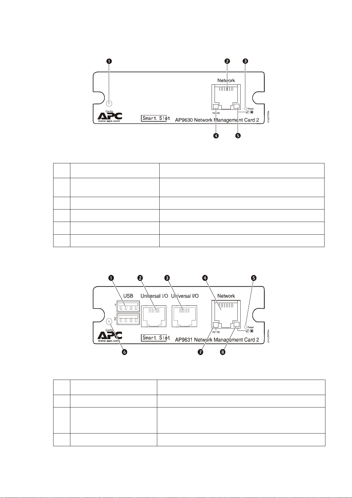
Front Panel (AP9630)
Features
Item Description
Serial configuration port Connects the Management Card to a local computer to configure
10/100 Base-T connector Connects the Management Card to the Ethernet network.
Reset button Resets the Management Card while power remains on.
initial network settings or access the command line interface.
Link-RX/TX (10/100) LED See “Link-RX/TX (10/100) LED” on page 7.
Status LED See “Status LED” on page 6.
Front Panel (AP9631)
Features
Item Description
USB ports Reserved for future use.
Sensor ports Connect temperature sensors, temperature/humidity sensors, or
10/100 Base-T connector Connects the Management Card to the Ethernet network.
relay input/output connectors that support two input contacts and
one output relay.
5UPS Network Management Card 2 User’s Guide

Item Description
Reset button Resets the Management Card while power remains on.
Serial configuration port Connects the Management Card to a local computer to configure
Link-RX/TX (10/100) LED See “Link-RX/TX (10/100) LED” on page 7.
Status LED See “Status LED” on page 6.
LED Descriptions
Status LED
This LED indicates the status of the Management Card.
Condition Description
Off One of the following situations exists:
• The Management Card is not receiving input power.
• The Management Card is not operating properly. It may need to be repaired or
replaced. Contact APC Customer Support. See “APC Worldwide Customer
Support” on page 108.
initial network settings or access the command line interface.
Solid green The Management Card has valid TCP/IP settings.
Solid orange A hardware failure has been detected in the Management Card. Contact APC
Customer Support. See “APC Worldw ide Cust omer Support ” on page 10 8.
Flashing green The Management Card does not have valid TCP/IP settings.
Flashing orange The Management Card is making BOOTP requests.
Alternately flashing
green and orange
1. If you do not use a BOOTP or DHCP server, see the Network Management Card Installation Manual provided
in printed format and on the APC Network Management Card Utility CD in PDF to configure the TCP/IP settings
of the Management Card.
2. To use a DHCP server, see “TCP/IP and Communication Settings” on page 60.
If the LED is flashing slowly, the Management Card is making DHCP2 requests.
If the LED is flashing rapidly, the Management Card is starting up.
1
1
1
UPS Network Management Card 2 User’s Guide6

Link-RX/TX (10/100) LED
This LED indicates the network status of the Management Card.
Condition Description
Off One or more of the following situations exist:
• The Management Card is not receiving input power.
• The cable that connects the Management Card to the network is disconnected or
defective.
• The device that connects the Management Card to the network is turned off or not
operating correctly.
• The Management Card itself is not operating properly. It may need to be repaired or
replaced. Contact APC Customer Support. See “APC Worldwide Customer
Support” on page 108.
Solid green The Management Card is connected to a network operating at 10 Megabits per
second (Mbps).
Solid orange The Management Card is connected to a network operating at 100 Mbps.
Flashing green The Management Card is receiving or transmitting data packets at 10 Mbps.
Flashing orange The Management Card is receiving or transmitting data packets at 100 Mbps.
Watchdog Features
Overview
To detect internal problems and recover from unanticipated inputs, the Management Card uses internal,
system-wide watchdog mechanisms. When it restarts to recover from an internal problem, a System:
Warmstart event is recorded in the event log.
Network interface watchdog mechanism
The Management Card implements internal watchdog mechanisms to protect itself from becoming
inaccessible over the network. For example, if the Management Card does not receive any network
traffic for 9.5 minutes (either direct traffic, such as SNMP, or broadcast traffic, such as an Address
Resolution Protocol [ARP] request), it assumes that there is a problem with its network interface and
restarts.
Resetting the network timer
To ensure that the Management Card does not restart if the network is quiet for 9.5 minutes, the
Management Card attempts to contact the default gateway every 4.5 minutes. If the gateway is present, it
responds to the Management Card, and that response restarts the 9.5-minute timer. If your application
does not require or have a gateway, specify the IP address of a computer that is running on the network
and is on the same subnet. The network traffic of that computer will restart the 9.5-minute timer
frequently enough to prevent the Management Card from restarting.
7UPS Network Management Card 2 User’s Guide

Command Line Interface
How To Log On
Overview
You can use either a local (serial) connection, or a remote (Telnet or SSH) connection with a computer
on the same network as the Management Card to access the command line interface.
Use case-sensitive user name and password entries to log on (by default, apc and apc for an
Administrator, or device and apc for a Device User). A Read-Only User cannot access the command line
interface.
If you cannot remember your user name or password, see “How to Recover from a Lost
Password” on page 4.
Remote access to the command line interface
You can access the command line interface through Telnet or SSH. Telnet is enabled by default. Enabling
SSH disables Telnet.
To enable or disable these access methods, use the Web interface. On the Administration tab, select
Network on the top menu bar, and then the access option under Console on the left navigation menu.
Telnet for basic access. Telnet provides the basic security of authentication by user name and
password, but not the high-security benefits of encryption.
To use Telnet to access the command line interface:
1. From a computer that has access to network on which the Management Card is installed, at a
command prompt, type
telnet 139.225.6.133, when the Management Card uses the default T e ln et por t of 23), and
press
ENTER.
If the Management Card uses a non-default port number (from 5000 to 32768), you must
include a colon or a space, depending on your Telnet client, between the IP address (or DNS
name) and the port number. (These are commands for general usage: some clients don’t allow
you to specify the port as an argument and some types of Linux might want extra commands).
2. Enter the user name and password (by default, apc and apc for an Administrator, or device and
apc for a Device User).
SSH for high-security access. If you use the high security of SSL for the Web interface, use SSH for
access to the command line interface. SSH encrypts user names, passwords, and transmitted data. The
interface, user accounts, and user access rights are the same whether you access the command line
interface through SSH or Telnet, but to use SSH, you must first configure SSH and have an SSH client
program installed on your computer.
telnet and the IP address for the Management Card (for example,
UPS Network Management Card 2 User’s Guide8

Local access to the command line interface
For local access, use a computer that connects to the Management Card through the serial port to access
the command line interface:
1. Select a serial port at the computer and disable any service that uses the port.
2. Connect the provided serial cable (APC part number 940-0299) from the selected port on the
computer to the configuration port at the Management Card.
3. Run a terminal program (e.g., HyperTerminal), and configure the selected port for 9600 bps, 8
data bits, no parity, 1 stop bit, and no flow control.
4. Press
ENTER. At the prompts, enter your user name and password.
Main Screen
Sample main screen
Following is an example of the screen displayed when you log on to the command line interface at the
Management Card.
Schneider Electric Network Management Card AOS vx.x.x
(c)Copyright 2009 All Rights Reserved Symmetra APP vx.x.x
------------------------------------------------------------------------- Name : Test Lab Date : 10/30/2009
Contact : Don Adams Time : 5:58:30
Location : Building 3 User : Administrator
Up Time : 0 Days, 21 Hours, 21 Minutes Stat : P+ N+ A+
APC>
Information and status fields
Main screen information fields.
• Two fields identify the APC operating system (AOS) and application (APP) firmware versions.
The application firmware name identifies the device that connects to the network through this
Management Card. In the example above, the Management Card uses the application firmware for
a Symmetra UPS.
Network Management Card AOS vx.x.x
Symmetra APP vx.x.x
• Three fields identify the system name, contact person, and location of the Management Card. (In
the Web interface, select the Administration tab, General in the top menu bar, and
Identification in the left navigation menu to set these values.)
Name : Test Lab
Contact: Don Adams
Location: Building 3
9UPS Network Management Card 2 User’s Guide

• The Up Time field reports how long the Management Card has been running since it was last
turned on or reset.
Up Time: 0 Days 21 Hours 21 Minutes
• Two fields report when you logged in, by date and time.
Date : 10/30/2009
Time : 5:58:30
• The User field reports whether you logged in through the Administrator or Device Manager
account. (The Read Only User account cannot access the command line interface.)
When you log on as Device Manager (equivalent to Device User in the Web interface), you can
access the event log, configure some UPS settings, and view the number of active alarms.
User : Administrator
Main screen status fields.
• The Stat field reports the Management Card status. The middle status varies according to whether
you are running IPv4, IPv6, or both, as indicated in the second table below.
Stat : P+ N+ A+
P+ The APC operating system (AOS) is functioning properly.
IPv4
only
N+ N6+ N4+ N6+ The network is functioning properly.
N? N6? N4? N6? A BOOTP request cycle is in progress.
N– N6– N4- N6-
N! N6! N4! N6!
A+ The application is functioning properly.
A– The application has a bad checksum.
A? The application is initializing.
A! The application is not compatible with the AOS.
IPv6
only
* The N4 and N6 values can be different from one another: you could, for
example, have N4– N6+.
IPv4 and
IPv6* Description
The Management Card failed to connect to the
network.
Another device is using the IP address of the
Management Card.
If P+ is not displayed, contact APC Customer Support. See “APC Worldwide Customer
Support” on page 108.
Note: To view the status of the UPS, type
UPS Network Management Card 2 User’s Guide10
ups -st.

How to Use the Command Line Interface
Overview
The command line interface provides options to configure the network settings and manage the UPS and
its Management Card.
How to enter commands
At the command line interface, use commands to configure the Management Card. To use a command,
type the command and press
mixed case. Options are case-sensitive.
While using the command line interface, you can also do the following:
ENTER. Commands and arguments are valid in lowercase, uppercase, or
• Type
? and press ENTER to view a list of available commands, based on your account type.
To obtain information about the purpose and syntax of a specified command, type the
command, a space, and
options, type:
radius ?
or
radius help
• Press the UP arrow key to view the command that was entered most recently in the session. Use
UP and DOWN arrow keys to scroll through a list of up to ten previous commands.
the
• Type at least one letter of a command and press the
commands that match the text you typed in the command line.
• Type
• Type
ups -st to view the status of the UPS.
exit or quit to close the connection to the command line interface.
Command syntax
Item Description
- Options are preceded by a hyphen.
< > Definitions of options are enclosed in angle brackets. For example:
-dp <device password>
? or the word help. For example, to view RADIUS configuration
TAB key to scroll through a list of valid
[ ] If a command accepts multiple options or an option accepts mutually exclusive
arguments, the values may be enclosed in brackets.
| A vertical line between items enclosed in brackets or angle brackets indicates that
the items are mutually exclusive. You must use one of the items.
11UPS Network Management Card 2 User’s Guide

Syntax examples
A command that supports multiple options:
user [-an <admin name>] [-ap <admin password>]
In this example, the user command accepts the option -an, which defines the Administrator user name,
and the option
-ap, which defines the Administrator password. To change the Administrator user name
and password to XYZ:
1. Type the
user -ap XYZ
user command, one option, and the argument XYZ:
2. After the first command succeeds, type the user command, the second option, and the argument
XYZ:
user -an XYZ
A command that accepts mutually exclusive arguments for an option:
alarmcount -p [all | warning | critical]
In this example, the option -p accepts only three arguments: all, warning, or critical. For
example, to view the number of active critical alarms, type:
alarmcount -p critical
The command will fail if you type an argument that is not specified.
Command Response Codes
The command response codes enable scripted operations to detect error conditions reliably without
having to match error message text.
The CLI reports all command operations with the following format:
E [0–9][0–9][0–9]: Error message
Code Error message
E000 Success
E001 Successfully Issued
E002 Reboot required for change
to take effect
E100 Command failed
E101 Command not found
E102 Parameter Error
E103 Command Line Error
E104 User Level Denial
E105 Command Prefill
E106 Data Not Available
E107 Serial communication with
the UPS has been lost
UPS Network Management Card 2 User’s Guide12

Command Descriptions
?
Access: Administrator, Device User
Description: View a list of all the CLI commands available to your account type. To view help text for
a specific command, type the command followed by a question mark.
Example: To view a list of options that are accepted by the alarmcount command, type:
alarmcount ?
about
Access: Administrator, Device User
Description: View hardware and firmware information. This information is useful in troubleshooting
and enables you to determine if updated firmware is available at the APC Web site.
alarmcount
Access: Administrator, Device User
Description:
Option Arguments Description
-p all View the number of active alarms repor ted by the Management Card. Informa tion
about the alarms is provided in the event log.
warning View the number of active warning alarms.
critical View the number of active critical alarms.
Example:
alarmcount -p warning
To view all active warning alarms, type:
boot
Access: Administrator only
Description: Define how the Management Card will obtain its network settings, including the IP
address, subnet mask, and default gateway. Then configure the BOOTP or DHCP server settings.
Option Argument Description
-b
<boot
mode>
dhcp | bootp |
manual
Define how the TCP/IP settings will be configured when the Management
Card turns on, resets, or restarts. See “TCP/IP and Communication
Settings” on page 60 for information about each boot mode setting.
-c enable | disable dhcp and dhcpBootp boot modes only. Enable or disable the
requirement that the DHCP server provide the APC cookie.
The default values for these three settings generally do not need to be changed:
-v <vendor class>: APC
-i <client id>: The MAC address of the Management Card, which uniquely identifies it on the network
-u <user class>: The name of the application firmware module
13UPS Network Management Card 2 User’s Guide

Example: To use a DHCP server to obtain network settings:
1. Type
boot -b dhcp
2. Enable the requirement that the DHCP server provide the APC cookie:
boot -c enable
3. Define the number of retries that will occur if the Management Card does not receive a valid
response from the initial request:
boot -s 5
cd
Access: Administrator, Device User
Description: Navigate to a folder in the directory structure of the Management Card.
Example 1: To change to the ssh folder and confirm that an SSH security certificate was uploaded to
the Management Card:
1. Type
2. Type
cd ssh and press ENTER.
dir and press ENTER to list the files stored in the SSH folder.
Example 2: To return to the main directory folder, type:
cd ..
console
Access: Administrator only
Description: Define whether users can access the command line interface using Telnet, which is
enabled by default, or Secure SHell (SSH), which provides protection by transmitting user names,
passwords, and data in encrypted form. You can change the Telnet or SSH port setting for additional
security. Alternately, disable network access to the command line interface.
Option Argument Description
-S disable | telnet | ssh Configure access to the command line interface, or use the disable
command to prevent access.. Enabling SSH enables SCP and disables
Telnet.
-pt <telnet port n> Define the Teln et port used to com municate with the Management Card (23
by default).
-ps <SSH port n> Define the SSH port used to communicate with the Management Card (22 by
default).
-b 2400 | 9600 |
19200 | 38400
Configure the speed of the serial port connection (9600 bps by default).
Example 1: To enable SSH access to the command line interface, type:
console -S ssh
Example 2: To change the Telnet port to 5000, type:
console -pt 5000
UPS Network Management Card 2 User’s Guide14

date
Access: Administrator only
Definition: Configure the date used by the Management Card.
To configure an NTP server to define the date and time for the Management Card, see “Set
the Date and Time” on page 78.
Option Argument Description
-d <“datestring”> Set the current date. Use the date format specified by the date -f command.
-t <00:00:00> Configure the current time, in hours, minutes, and seconds. Use the 24-hour
clock format.
-f mm/dd/yy |
dd.mm.yyyy |
mmm-dd-yy |
dd-mmm-yy |
yyyy-mm-dd
-z <time zone
offset>
Select the numerical format in which to display all dates in this user interface.
Each letter m (for month), d (for day), and y (for year) represents one digit.
Single-digit days and months are displayed with a leading zero.
Set the difference with GMT in order to specify your time zone. This enables
you to synchonize with other people in different time zones.
Example 1: To display the date using the format yyyy-mm-dd, type:
date -f yyyy-mm-dd
Example 2: To define the date as October 30, 2009, using the format configured in the preceding
example, type:
date -d “2009-10-30”
Example 3: T o define the time as 5:21:03 p.m., type:
date -t 17:21:03
delete
Access: Administrator only
Description: Delete the event or data log, or delete a file in the file system.
Argument Description
<file name> Type the name of the file to delete.
Example: To delete the event log:
1. Navigate to the folder that contains the file to delete. For example, to navigate to the
type:
cd logs
2. To view the files in the
dir
logs folder, type:
The file event.txt is listed.
3. Type
delete event.txt.
logs folder,
15UPS Network Management Card 2 User’s Guide

dir
Access: Administrator, Device User
Description: View the files and folders stored on the Management Card.
dns
Access: Administrator
Description: Configure the manual Domain Name System (DNS) settings.
Parameter Argument Description
-OM enable | disable
-p <primary DNS
server>
-s <secondary DNS
server>
-d <domain name> Set the domain name.
-n <domain name
IPv6>
-h <host name> Set the host name.
Override the manual DNS.
Set the primary DNS server.
Set the secondary DNS server.
Set the domain name IPv6.
eventlog
Access: Administrator, Device User
Description: V iew the date and time you retrieved the event log, the status of the UPS, and the status of
sensors connected to the Management Card. View the most recent device events, and the date and time
they occurred. Use the following keys to navigate the event log:
Key Description
ESC
Close the event log and return to the command line interface.
ENTER
SPACEBAR
B View the preceding page of the event log. This command is not available at the main page of the
D Delete the event log. Follow the prompts to confirm or deny the deletion. Deleted events cannot
Update the log display. Use this command to view events that were recorded after you last
retrieved and displayed the log.
View the next page of the event log.
event log.
be retrieved.
exit
Access: Administrator, Device User
Description: Exit from the command line interface session.
UPS Network Management Card 2 User’s Guide16

format
Access: Administrator only
Description: Reformat the file system of the Management Card and erase all security certificates,
encryption keys, configuration settings, and the event and data logs. Be careful with this command.
Note: To reset the Management Card to its default configuration, use the
resetToDef
command.
FTP
Access: Administrator only
Description: Enable or disable access to the FTP server. Optionally, change the port setting to the
number of any unused port from 5001 to 32768 for added security.
Option Argument Definition
-p <port number> Define the TCP/IP port that the FTP server uses to communicate with the
Management Card (21 by default). The FTP server uses both the specified port
and the port one number lower than the specified port.
-S enable | disable Configure access to the FTP server.
Example: To change the TCP/IP port to 5001, type:
ftp -p 5001
help
Access: Administrator, Device User
Description: V iew a list of all the CLI commands available to your account type. To view help text
for a specific command, type the command followed by
Example 1: To view a list of commands available to someone logged on as a Device User, type:
help
Example 2: To view a list of options that are accepted by the alarmcount command, type:
alarmcount help
help.
netstat
Access: Administrator, Device User
Description: View the status of the network and all active IPv4 and IPv6 addresses.
ntp
Access: Administrator, Device User
Description: View and configure the network time protocol parameters.
17UPS Network Management Card 2 User’s Guide

Option Argument Definition
-OM enable | disable
-p <primary NTP server> Specify the primary server.
-s <secondary NTP server> Specify the secondary server.
Override the manual settings.
Example 1: To enable the override of manual setting, type:
ntp -OM enable
Example 2: To spe cify the primary NTP server, type:
ntp -p 150.250.6.10
ping
Access: Administrator, Device User
Description. Determine whether the device with the IP address or DNS name you specify is
connected to the network.
Four inquiries are sent to the address.
Argument Description
<IP address or DNS name> Type an IP address with the format xxx.xxx.xxx.xxx, or the DNS name configured
by the DNS server.
Example: To determine whether a device with an IP address of 150.250.6.10 is connected to the
network, type:
ping 150.250.6.10
portSpeed
Access: Administrator
Description:
Option Arguments Description
-s auto | 10H | 10F |
100H | 100F
Example:
To configure the TCP/IP port to communicate using 100 Mbps with half-duplex
Define the communication speed of the Ethernet port. The auto command
enables the Ethernet devices to negotiate to transmit at the highest possible
speed. See “Port Speed” on page 62 for more information about the port speed
settings.
communication (communication in only one direction at a time), type:
portspeed -s 100H
prompt
Access: Administrator, Device User
UPS Network Management Card 2 User’s Guide18

Description: Configure the command line interface prompt to include or exclude the account type
of the currently logged-in user.
Any user can change this setting; all user accounts will be updated to
use the new setting.
Option Argument Description
-s long The prompt includes the account type of the currently logged-in user.
short The default setting. The prompt is four characters long: APC>
Example: To include the account type of the currently logged-in user in the command prompt, type:
prompt -s long
quit
Access: Administrator, Device User
Description: Exit from the command line interface session (this works the same as the exit command).
radius
Access: Administrator only
Description: View the existing RADIUS settings, enable or disable RADIUS authentication, and
configure basic authentication parameters for up to two RADIUS servers.
For a summary of RADIUS server configuration and a list of supported RADIUS servers, see
“Configuring the RADIUS Server” on page 58.
Additional authentication parameters for RADIUS servers are available at the Web interface
of the Management Card. See “RADIUS” on page 57 for more information.
For detailed information about configuring your RADIUS server, see the Security Handbook,
available on the APC Network Management Card Utility CD and at the APC Web site,
www.apc.com.
Option Argument Description
-a local |
radiusLocal |
radius
-p1
-p2
<server IP> The server name or IP address of the primary or secondary RADIUS server.
Configure RADIUS authentication:
local—RADIUS is disabled. Local authentication is enabled.
radiusLocal—RADIUS, then Local Authentication. RADIUS and local
authentication are enabled. Authentication is requested from the RADIUS
server first. If the RADIUS server fails to respond, local authentication is used.
radius—RADIUS is enabled. Local authentication is disabled.
N
OTE: RADIUS servers use port 1812 by default to authenticate users. To use
a different port, add a colon followed by the new port number to the end of the
RADIUS server name or IP address.
-s1
-s2
<server secret> The shared secret between the primary or secondary RADIUS server and the
Management Card.
19UPS Network Management Card 2 User’s Guide

Option Argument Description
-t1
-t2
<server timeout> The time in seconds that the Management Card waits for a response from the
primary or secondary RADIUS server.
Example 1:
To view the existing RADIUS settings for the Management Card, type radius and press ENTER.
Example 2: To enable RADIUS and local authentication, type:
radius -a radiusLocal
Example 3: To configure a 10-second timeout for a secondary RADIUS server, type:
radius -t2 10
reboot
Access: Administrator
Description: Restart the interface of the Management Card.
resetToDef
Access: Administrator only
Description: Reset all parameters to their default.
Option Arguments Description
-p all | keepip Reset all configuration changes, including event actions, device settings, and,
optionally, TCP/IP configuration settings.
Example: To reset all of the configuration changes except the TCP/IP settings for the Management
Card, type:
resetToDef -p keepip
snmp, snmp3
Access: Administrator only
Description: Enable or disable SNMP 1 or SNMP 3.
Option Arguments Description
-S enable | disable Enable or display the respective version of SNMP, 1 or 3.
Example: To enable SNMP version 1, type:
snmp -S enable
UPS Network Management Card 2 User’s Guide20
Loading...