


Installa on Instruc ons and Use & Care Guide
Residential Gas
Water Heater
Residen al Atmospheric Gas Water Heater with the Flammable Vapor Igni on Resistant Safety System
Read this manual and the labels on the water heater before you install, operate, or service it. If you have di culty following the direc ons, or aren’t sure you can safely and properly do any of this work yourself:
• Call our Technical Assistance Hotline at 1-800-527-1953. We can help you with installa on, opera ons, troubleshoo ng, or maintenance. Before you call, write down the model and serial number from the water heater’s data plate.
Incorrect installa on, opera on, or service can damage the water heater, your house and other property, and present risks including fire, scalding, electric shock, and explosion, causing serious injury or death.
Table of Contents Page |
|
IMPORTANT SAFETY INFORMATION |
............................................. 3 |
GETTING STARTED ........................................................................ |
7 |
INSTALLATION............................................................................. |
14 |
OPERATION................................................................................. |
23 |
TROUBLESHOOTING ................................................................... |
25 |
MAINTENANCE ........................................................................... |
28 |
NOTES......................................................................................... |
31 |
REPAIR PARTS ............................................................................. |
35 |
WARNING: If the informa on in these instruc ons is not followed exactly, a fire or explosion may result causing property damage, personal injury or death.
Do not store or use gasoline or other flammable vapors and liquids in the vicinity of this or any other appliance.
WHAT TO DO IF YOU SMELL GAS
•Do not try to light any appliance.
•Do not touch any electrical switch; do not use any phone in your building.
•Immediately call your gas supplier from a neighbor’s phone. Follow the gas supplier’s instruc ons.
•If you cannot reach your gas supplier, call the fire department.
Installa on and service must be performed by a qualified installer, service agency or the gas supplier.
LOW LEAD
CONTENT
Keep this manual in the pocket on heater for future reference whenever maintenance, adjustment or service is required.
Retain your original receipt as proof of purchase.
100263112 January 2015
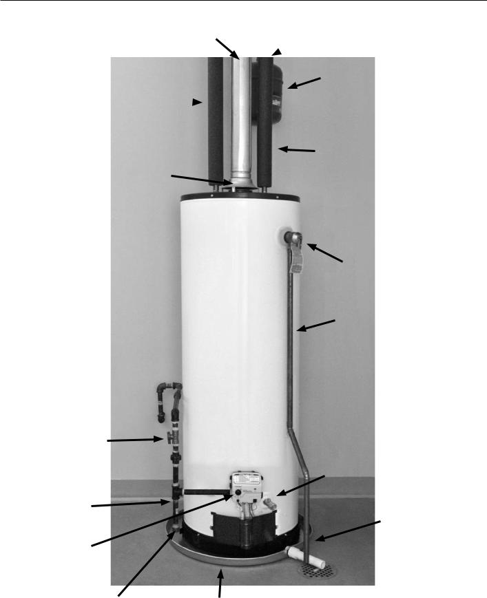
COMPLETED INSTALLATION TYPICAL
Vent pipe
Hot  water
water
line
Dra hood
Gas supply shut o
Gas supply
Gas control valve/thermostat
Cold water
 shut o
Expansion tank (Connect to cold water supply)
Cold water line
T&P relief valve
T&P discharge pipe
Drain valve
Drain pan discharge pipe
Sediment Trap |
Metal drain pan |
|
IMPORTANT SAFETY INFORMATION
Read and follow all safety messages and instruc ons in this manual.
This is the safety alert symbol. It is used to alert you to poten al physical injury hazards. Obey all safety messages that follow this symbol to avoid possible property damage, serious injury or death. Do not remove any
permanent instruc ons, labels, or the data plate from either the outside of the water heater or on the inside of the access panels. Keep this manual near the water heater.
|
|
|
DANGER indicates hazardous situa- |
|
DANGER |
|
|
|
|
on that, if not avoided, will result |
|
|
|
in death or serious injury. |
|
|
|
|
|
|
|
|
|
|
|
|
WARNING indicates a hazardous |
|
WARNING |
||
|
|
situa on that, if not avoided, could |
|
|
|
result in death or serious injury. |
|
|
|
|
|
|
|
|
CAUTION indicates a hazardous |
|
CAUTION |
||
|
|
result in minor or moderate injury. |
|
|
|
|
situa on that, if not avoided, could |
|
|
|
|
|
|
|
NOTICE indicates prac ces not |
|
NOTICE |
||
|
|
related to physical injury. |
|
|
|
|
|
|
|
|
|
|
|
|
|
 WARNING! If the informa on in these instruc ons is not followed exactly, a fire or explosion may result causing property damage, personal injury or death. Do not store or use gasoline or other flammable vapors and liquids in the vicinity of this or any other appliance.
An odorant is added by the gas supplier to the gas used by this water heater. This odorant may fade over an extended period of me. Do not depend upon this odorant as an indica on of leaking gas. We recommend installing a fuel gas and carbon monoxide detector.
 The California Safe Drinking Water and Toxic Enforcement Act requires the Governor of California to publish a list of substances known to the State of California to cause cancer, birth defects, or other reproduc ve harm, and requires businesses to warn of poten al exposure to such substances.
WARNING! This product contains a chemical known to the State of California to cause cancer, birth defects, or other reproduc ve harm.
This water heater can cause low-level exposure to some of the substances included in the act.
Important informa on to keep
Fill out this sec on and keep this manual in the pocket of the water heater for reference.
Date Installed:
Model number:
Serial number:
Maintenance performed:* |
Date: |
|
|
|
|
|
|
|
|
|
|
|
|
|
|
|
|
|
|
|
|
*Drain and flush tank and remove and inspect anode rod a er first six months of opera on and at least annually therea er. Operate the Temperature and Pressure Relief Valve (T&P) annually and inspect T&P valve every 2-4 years (see the label on the T&P valve for maintenance schedule). See the Maintenance sec on for more informa on about maintaining this water heater.
SAFETY
Residen al Standard Gas Water Heater Use and Care Guide • 3
SAFETY
IMPORTANT SAFETY INFORMATION
To reduce the risk of property damage, serious injury or death,
read and follow the precau ons below, all labels on the water heater, and
the safety messages and instruc ons throughout this manual.
RISKS DURING INSTALLATION AND MAINTENANCE
Li ing Risk
 WARNING! The water heater is heavy. Follow these precau-
ons to reduce the risk of property damage, injuries from
li |
ing or impact injuries from dropping |
the water heater. |
|
• |
Use at least two people to li the |
|
water heater. |
•Be sure you both have a good grip before li ing.
•Use an appliance dolly or hand truck to move the water heater.
Explosion Risk
 WARNING! Read the water heater’s data plate to determine the type of gas required. Failure to follow these instruc ons can result in serious injury or death from explosion, fire or carbon monoxide poisoning.
•Do not connect a natural gas water heater to an L.P. gas supply.
•Do not connect an L.P. gas water heater to a natural gas supply.
•Use a new CSA approved gas supply line.
•Install a shut-o valve on the gas supply line.
Gas Pressure
 WARNING! The gas supply pressure must not exceed the maximum supply pressure as stated on the water heater’s data plate. The minimum supply pressure is for the purpose of input adjustment. L.P. gas supply pressure must not exceed 13” water column. Have a qualified person (licensed plumber, gas company personnel, or authorized service technician) check for proper L.P. gas pressure. L.P. gas pressures exceeding 13” water column can result in serious injury or death from explosion or fire.
RISKS DURING OPERATION


 Scalding Risk
This water heater can make water hot
enough to cause severe burns instantly, resul ng in severe injury or death.
•Feel water before bathing or showering.
•To reduce the risk of scalding, install Thermosta c Mixing Valves (temperature limi ng valves) at each point-of-use. These valves automa cally mix hot and cold water to limit the temperature at the tap. Follow manufacturer’s instruc ons for installa on and adjustment of the valves.
•The gas control valve on this water heater has been factory set to its
lowest se ng to reduce the risk of scalding. Higher temperatures increase the risk of scalding, but even at 120°F, hot water can scald. If you choose a higher temperature se ng, Thermosta c Mixing Valves located at each point-of-use are par cularly important to help avoid scalding.
Table 1
|
Time to Produce |
Temperature |
a Serious Burn |
120°F(49°C) |
Morethan5minutes |
|
|
125°F(52°C) |
1½to2minutes |
|
|
130°F(54°C) |
About30seconds |
|
|
135°F(57°C) |
About10seconds |
|
|
140°F(60°C) |
Lessthan5seconds |
|
|
145°F(63°C) |
Lessthan3seconds |
|
|
150°F(66°C) |
About1½seconds |
|
|
155°F(68°C) |
About1second |
|
|
For informa on about changing the factory temperature se ng, refer to the “Adjus ng the Temperature” sec-
on in this manual .
Even if you set the water heater’s gas control valve to a low se ng, higher water temperatures may occur in certain circumstances:
•In some cases, repeated small draws of water can cause the hot and cold water in the tank to “stack” in layers. If this happens, the water can be as much as thirty degrees ho er than
the gas control valve se ng. This temperature varia on is the result of your usage pa ern and is not a malfunc on.
•Water temperature will be ho er if someone adjusted the gas control
valve to a higher se ng.
•Problems with the gas control valve or other malfunc ons may result in higher than expected water temperatures.
•If the water heater is in a hot environment, the water in the tank can become as hot as the surrounding air, regardless of the temperature se ng.
4 • Residen al Standard Gas Water Heater Use and Care Guide
IMPORTANT SAFETY INFORMATION
•If the water supplied to the water heater is pre-heated (for example, by a solar system) the temperature in the tank may be higher than the
water heater’s temperature se ng.
•Should overhea ng occur or the burner fail to shut o , turn o the manual gas supply valve to the water heater and call a qualified person.
To reduce the risk of unusually hot water reaching the fixtures in the house, install Thermosta c Mixing Valves at each point-of-use.
If anyone in your home is at par cular risk of scalding (for example, the elderly, children, or people with disabili es) or if there is a local code or state law requiring a certain water temperature at the hot water tap, these precau ons are par cularly important.
According to a na onal standard (ASSE 1070) and many local plumbing codes, the water heater’s gas control valve should not be used as the sole means to regulate water temperature and avoid scalds.
Properly adjusted Thermosta c Mixing Valves installed at each point-of-use allow you to set the tank temperature to a higher se ng without increasing risk of scalds. A higher temperature se ng allows the tank to provide much more hot water and can help provide proper water temperatures for appliances such as dishwashers and washing machines. Higher tank temperatures (140°F)
also kill bacteria that cause a condion known as “smelly water” and can
reduce the levels of bacteria that cause water-borne diseases.
Water Contamina on Risk
Do not use chemicals that could contaminate the potable water supply. Do not use piping that has been treated with chromates, boiler seal, or other chemicals.
Fire Risk
This water heater is equipped with a Flammable Vapor Igni on Resistance (FVIR) system.
FVIR is designed to reduce the risk of flammable vapor-related fires. FVIR makes this product more sensi ve to installa on errors or improper installa-
on environments. The FVIR system will not prevent a possible fire/explosion if the igniter is depressed and flammable vapors have accumulated in the combus-
on chamber with the pilot light o .
Do not a empt to light this appliance, or depress the igniter bu on, if you suspect flammable vapor have accumulated inside or outside the appliance. Immediately call a qualified person to inspect the appliance. Water heaters subjected to a flammable vapors incident will show a discolora on on the flame arrestor and require replacement of the en re water heater. Improper installa on or an inadequate air supply can also cause the FVIR system to disable the water heater.
 WARNING! This water heater has a rese able thermal switch installed as part of the FVIR system. Do not
a empt to disable or modify this feature in any way. Doing so can lead to fire, explosion or excessive and abnormal produc on of carbon monoxide.
To reduce the risk of a fire that could result in property damage, or serious injury or death:
•Do not store things that can burn easily such as paper or clothes next to the water heater.
•Do not store or use gasoline or other flammable substances in the vicinity of this or any other appliance.
•Keep the water heater from becoming wet. Immediately shut the water heater o and have it inspected by a qualified person if you find that the wiring, thermostat(s) or surrounding insula on have been exposed to water in any way (e.g., leaks from plumbing, leaks from the water heater itself can damage property and could cause a fire risk). If the water heater is subjected to flood condi ons or the thermostat(s) have been submerged in water, the en re water heater must be replaced.
•Replace the water heater’s viewport if glass is missing or damaged. Repair the combus on chamber door seals if damaged.
Explosion Risk
High temperatures and pressures in the water
heater tank can cause an explosion resul ng in property damage, serious injury or death. A new Temperature and Pressure (T&P) Relief Valve is included with your water heater to reduce risk of explosion by discharging hot water. Addi onal temperature and pressure protec ve equipment may be required by local codes.
A na onally recognized tes ng laboratory maintains periodic inspec on of the valve produc on process and
cer fies that it meets the requirements for Relief Valves for Hot Water Supply Systems, ANSI Z21.22. The T&P Relief Valve’s relief pressure must not exceed the working pressure ra ng of the water heater as stated on the ra ng plate.
Maintain the T&P Relief Valve properly. Follow the maintenance instruc ons provided by the manufacturer of the T&P Relief Valve (label a ached to T&P Relief Valve). An explosion could occur
SAFETY
Residen al Standard Gas Water Heater Use and Care Guide • 5
SAFETY
IMPORTANT SAFETY INFORMATION
if the T&P Relief Valve or discharge pipe is blocked. Do not cap or plug the T&P Relief Valve or discharge pipe.
Fire and Explosion Risk if Hot Water is Not Used for Two Weeks or More.
 CAUTION! Hydrogen gas builds up in a hot water system when it is not used for a long period (two weeks or more). Hydrogen gas is extremely flammable. If the hot water system has not been used for two weeks or more, open a hot water faucet for several minutes at the kitchen sink before using any electrical appliances connected to the hot water system. If hydrogen is present there will probably be an unusual sound such as “air” escaping through the pipe as hot water begins to flow. Do not smoke or have an open flame or other igni on source near the faucet while it is open.
Carbon Monoxide Risk
 WARNING! This water heater operates by burning gas. Carbon monoxide is a colorless, odorless, gas that is a by-product of burning of fuels such as coal, wood, charcoal, oil, kerosene, propane, and natural gas. Breathing excessive and abnormal amounts of carbon monoxide can cause carbon monoxide poisoning, resul ng in serious injury or death. This water heater must be supplied with adequate combus on air and
must be properly vented to the outdoors. Have a qualified person (licensed plumber, authorized gas
company personnel, or authorized service technician) install the ven ng system using these installa on
instruc ons. When the installa on is complete, check the vent’s dra using the instruc ons on pages 23-24.
•Install a fuel gas and carbon monoxide detector in the living areas of your home.
•Do not install this water heater in a mobile home or manufactured housing.
•Failure to follow these instrucons can result in serious injury
or death from carbon monoxide poisoning.
Burn Risk
This water heater’s venting system can become
hot enough to burn. Do not touch the ven ng system while water heater is on, or un l the water heater is turned o and the ven ng allowed to cool.
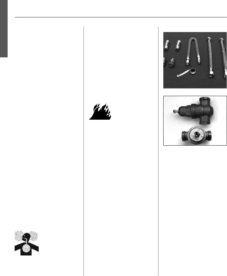
Installa on Accessories
Figure 1 - Gas Water Heater Hook-Up Kit
Figure 2 - Install a Pressure Reducing Valve set to 50 to 60 PSI.
6 • Residen al Standard Gas Water Heater Use and Care Guide

GETTING STARTED
Review all of the instruc ons 1 before you begin work.
Improper installa on can damage the water heater, your home and other property, and can present risks of serious injury or death.
This water heater is design- 2 cer fied by CSA Interna onal
as a Category I, non-direct vented water heater which takes its combus on air either from the installa-
on area or from air ducted to the unit from the outside. This water heater must be installed according to all local and state codes or, in the absence of local and state codes, the “Na onal Fuel Gas Code”, ANSI Z223.1(NFPA 54)-current edi on. This is available from the following:
CSA America, Inc.
8501 East Pleasant Valley Road
Cleveland, OH 44131
Na onal Fire Protec on Associa on 1 Ba erymarch Park
Quincy, MA 02269
Check with local code o cials about codes governing this installa on. Have your installa on inspected by a code o cial to ensure the installa on meets all local codes.
NOTICE: If you lack the necessary skills required to properly install this water heater, or you have di culty following the instruc ons, you should not proceed but have a qualified person perform the installa on of this water heater.
Massachuse s code requires this water heater to be installed in accordance with Massachuse s 248-CMR 2.00 and 248-CMR 5.00: State Plumbing Code. Other local and state authori es may have similar requirements or other
codes applicable to the installa on of this water heater.
Before you start, be sure you 3 have the following tools and
supplies:
•Common plumbing tools (depending on what type of water pipes you have).
•Teflon® tape or pipe joint compound approved for potable water.
•For homes with copper pipes, you may purchase a Gas Water Heater Hook-Up Kit (available at your local plumbing supplier) with compression fi ngs that don’t require soldering. This kit includes two 12” flex water lines, two compression fi ngs, an 18” flexible gas line, two nipples, and Teflon® tape.
•For homes with plas c pipe, use threaded connectors suitable for the specific type of plas c pipe used: CPVC or PEX (cross-linked polyethylene). Do not use PVC pipe.
•Non-corrosive gas leak detec on solu on made from hand dishwashing soap mixed with water (1 part soap to 15 parts water) or children’s soap bubbles and a small, so -bristled brush.
•An appliance dolly or hand truck to move the water heater.
Recommended Accessories:
•A metal drain pan.
•Automa c water leak detec on and shut-o device.
•Pressure Reducing Valve.
•Thermal Expansion Tank.
•Thermosta c Mixing Valves at each point-of-use.
•Fuel gas and carbon monoxide detector.
Combus on and
Ven la on Air Supply
Before installing the water heater, you must determine the amount of air needed to supply this water heater and any other gas appliances in the same area and provide adequate air for combus on and ven la on. Consult a qualified person if you’re unsure of the proper way to supply air to your water heater.
 WARNING! This gas water heater requires an adequate source of clean air for combus on and ven la on.
Without su cient air, your water heater will have frequent pilot outages and may emit excessive and abnormal amounts of carbon monoxide.
Before beginning:
Calculate total BTU/HR ra ng of all appliances.
To calculate the combus on air and ven la on required, add up the total BTU/HR ra ngs of all gas burning appliances (e.g., water heaters, furnaces, clothes dryers) in the same area.
Your water heater’s BTU/HR ra ng is on the data plate, located next to the gas control valve/thermostat. The BTU/HR ra ngs should be on the other appliances’ data plates. If you have trouble determining the BTU/HR ra ngs, contact the manufacturer or have a qualified person determine the ven la-
on requirements. NOTICE: If you are replacing your old water heater with one that has a higher BTU/HR ra ng, the amount of ven la on required may be greater.
GETTING STARTED
Residen al Standard Gas Water Heater Use and Care Guide • 7

GETTING STARTED
GETTING STARTED
Example:
Gas Burning Appliance |
BTU/HR Ra |
ng |
Gas Water Heater |
40,000 |
|
|
|
|
Furnace |
75,000 |
|
Dryer |
20,000 |
|
|
|
|
|
|
|
Total |
135,000 |
|
Your Appliances: |
|
|
|
|
|
Gas Burning Appliance |
BTU/HR Ra |
ng |
|
|
|
Gas Water Heater |
|
|
|
|
|
|
|
|
|
|
|
|
|
|
|
|
|
Total
Table 2 provides examples of minimum square footage (area) required for various BTU/HR totals. Areas used for storage or which contain large objects containing less air than is assumed for the room sizes in Table 2 – see Op on A for more specific calcula ons.
Op on A: Installa on without outside ven la on (not recommended)
Ven la on with outside air is recommended for all installa ons. Even if the water heater is installed in a large, open room inside the house, outdoor air is usually needed because modern homes are very ghtly sealed and
o en do not supply enough air to the water heater. However, when installed in a large indoor space, it may be possible to provide enough air without outside ven la on. If you are unsure if your installa on loca on has enough ven la on, contact your local gas
u lity company or code o cials for a safety inspec on.
The following instruc ons will help determine if it may be possible to install without outside ven la on. Even if this may be possible, you will need to conduct the vent dra test on pages 23-24 when installa on is finished. If there is not enough ven la on, you will need to ven late with outside air.
Table 2
|
BTU/HR |
Minimum Square |
Typical Room |
|
|
Input |
Feet with 8’ Ceiling |
with 8’ Ceiling |
|
|
|
|
|
|
30,000 |
188 |
9 x 21 |
||
|
|
|
|
|
45,000 |
281 |
14 x 20 |
||
|
|
|
|
|
60,000 |
375 |
15 x 25 |
||
|
|
|
|
|
75,000 |
469 |
15 x 31 |
||
|
|
|
|
|
90,000 |
563 |
20 x 28 |
||
|
|
|
|
|
105,000 |
657 |
20 x 33 |
||
|
|
|
|
|
120,000 |
750 |
25 x 30 |
||
|
|
|
|
|
135,000 |
844 |
28 x 30 |
||
|
|
|
|
|
Check for Chemicals:
Installa ons where corrosive chemicals may be present require outside air. Air for combus on and ven la on must be clean and free of corrosive or acid-forming chemicals such as sulfur, fluorine, and chlorine. Ven la on with outside air will reduce these chemicals, but it may not completely eliminate them. Failure due to corrosive chemicals is not covered by the warranty. Examples of loca ons that require outside air due to chemicals include:
•Beauty salons
•Photo processing labs
•Indoor pools
• Laundry, hobby, or cra rooms
•Chemical storage areas
Products such as aerosol sprays, detergents, bleaches, cleaning solvents, gasoline, air fresheners, paint and varnish removers, and refrigerants should not be stored or used near the water heater.
A1: Calculate the air volume of the room
Air requirements depend on the size of the room.
Floor Area (Square feet) X Ceiling Height (feet) = Room Volume (cubic feet)
If there are large objects in the room (e.g., refrigerator, furnace, car), subtract their volume from the volume of the room to get a be er es mate of the air available.
Room Volume – Object Volume = Air
Volume
8 • Residen al Standard Gas Water Heater Use and Care Guide

GETTING STARTED
A2: Calculate required air volume
A water heater installed in an unconfined a c or garage requires that the space be at least 50 cubic feet per 1,000 BTU/ HR of the total input for all gas burning appliances in the same area.
[Total BTU/HR/1000] x 50 = Cubic feet of air required.
Example:
(135,000 / 1000) x 50 = 6,750
If the air volume of the room is less than the required air volume, you must provide two permanent outside air openings that draw in su cient air. Use Op on B.
If the air volume of the room is greater than the required air volume, it may be possible to install the water heater without outside ven la on.
A3: Check that combus on venla on is adequate
Because modern homes are o en wellsealed to prevent dra s, even a large room may not provide enough combus-
on air without ven la on. To confirm that your installa on has enough combus on air, conduct the vent dra test on pages 23-24 when installa on is finished.
Op on B: Install with outside ven la on
Ven la on with outside air is recommended, and, for most installa ons, is needed. There may be exis ng ven laon that is adequate, or you may need
to add more ven la on.
Supplying outside air to typically requires two openings. One opening must be within 12 inches from the floor and
the second opening must be within 12 inches from the ceiling. Although a single opening is not preferred, you may use a single opening to outside air if the mini-
mum free area is sized according to Table |
may be adequate). |
||||
3. Two openings must be used when |
B3: Determine minimum free |
||||
ven |
la |
ng with air from another room. |
area required for each vent |
||
The outside air can be taken from a |
opening |
||||
crawl space or a c open to the out- |
The size of the vent openings depends |
||||
doors and adequately ven lated. You |
on the total BTU/HR ra ng of all appli- |
||||
may use ver cal or horizontal ducts. |
ances in the space (use your calcula on |
||||
B2: Determine type of ven |
la- |
from “Before beginning”) and the type |
|||
of vent used. Table 3 provides the mini- |
|||||
on |
|
|
|||
|
|
mum free area for each vent opening |
|||
There are several types of ven la |
on |
||||
depending on the type of ven la on. |
|||||
that can be used : |
|
B4: Calculate minimum size of |
|||
1. |
Direct to outdoors |
|
|||
|
vent openings and ducts |
||||
2. |
Ver cal ducts |
|
|||
|
The vent cross-sec onal area needed to |
||||
3. |
Horizontal ducts |
|
|||
|
provide the free area depends on the |
||||
4. |
Single opening (not recom- |
|
|||
|
covering on the vent openings. Typical |
||||
|
mended; must be at least 100 |
|
|||
|
|
vents use louvers or grilles to protect |
|||
|
square inches. Not appropriate |
||||
|
the opening. The louver or grill itself |
||||
|
for confined spaces smaller than |
||||
|
blocks some of the free area, so the |
||||
|
50 cubic feet per 1,000 BTU/HR as |
||||
|
opening may need to be larger to meet |
||||
|
calculated in sec on A or when |
||||
|
the minimum free area requirements. |
||||
|
ge |
ng air from another room.) |
|||
|
Use the following formula to calculate |
||||
5. From a larger room inside the |
|
||||
|
house (not recommended – refer |
the required cross-sec onal area: |
|||
|
to sec on A above to determine if |
Cross-sec onal area = minimum free |
|||
|
the combined volume of the rooms |
area required ÷ percent free area of |
|||
Table 3
Minimum Free Area of Permanent Openings for Ven la on and Combus on Air Supply – All Air from Outdoors Only.
Based on the total BTU/HR input ra ng for all gas burning appliances within a confined space.
Opening Source |
Minimum Free Area |
|
Per Opening (sq. in.) |
|
|
*Direct to outdoors |
1 sq. in. per 4,000 BTU/HR (see figure on page 10) |
|
|
Ver cal ducts |
1 sq. in. per 4,000 BTU/HR (see figure on page 10) |
|
|
Horizontal ducts |
1 sq. in. per 2,000 BTU/HR (see figure on page 10) |
|
|
Single Opening |
1 sq. in. per 3,000 BTU/HR (see figure on page 10) |
|
|
*These openings connect directly with the outdoors through a ven lated a c, a ven lated crawl space, or through an outside wall.
GETTING STARTED
Residen al Standard Gas Water Heater Use and Care Guide • 9

GETTING STARTED
GETTING STARTED
covering (in decimals – e.g., 60% = .6)
For example, an installa on area that requires openings with 100 square inches of free area would need 134 square inch openings if using metal louvers rated at 75% free area (100 sq. in. ÷ .75 = 134 sq. in.).
If you do not know the % free area for your louver or grill, use the following values:
•For wood louvers or grilles: 20%
•For metal louvers or grilles: 60%
Follow these rules to ensure that vents and ducts provide adequate air flow:
•Each vent opening must be no smaller than 100 square inches .
•Ducts must have the same crosssec onal area as free area of the opening.
•Rectangular ducts must have a minimum dimension of no less than three inches .
•All screens must have mesh ¼” or larger.
•Moveable louvers must be locked open or interconnected with the equipment so that they open au-
toma cally during opera on.
•Keep louvers and grills clean and free of debris or other obstruc-
ons.
B5: Check that air source is clean and free of chemicals
Air for combus on and ven la on must be clean and free of corrosive or flammable chemicals. A failure due to corrosive chemicals in the air is not covered by the warranty. Combus-
on air must be free of acid-forming chemicals such as sulfur, fluorine, and chlorine. Be sure that air at the vent inlets is free of such chemicals.
B6: Check that combus on ven la on is adequate
To confirm that your installa on has enough combus on air, conduct the vent dra test on pages 23-24 when installa on is finished.
Combus on Air Supply Op ons
Figure 3 - Direct to outdoors openings
Figure 5 - Horizontal duct openings
Figure 6 - Single opening
Figure 4 - Vertical duct openings
10 • Residen al Standard Gas Water Heater Use and Care Guide
GETTING STARTED
Ven ng
 WARNING! Carbon Monoxide Hazard. This water heater must be supplied with adequate air and vented to outdoors. The vent system must be installed by a qualified person. Examples of a qualified person include gas technicians, authorized gas company personnel, and authorized service technicians. Failure to properly vent the water heater can result in severe injury or death from carbon monoxide poisoning.
The vent system must be installed according to local and state codes, or in the absence of local or state codes, the current edi on of the Na onal Fuel Gas Code, ANSI Z223.1 (NFPA 54). Do not common vent this water heater with any power vented appliance. Do not use a vent damper anywhere in the vent system of this water heater.
To reduce the risk of carbon monoxide poisoning, install a fuel gas and carbon monoxide detector. Install and maintain the detector in accordance with the manufacturer’s instruc ons and local codes.
Replacing a Water Heater Using the Exis ng Vent System
Read the “Installing a New Vent System” sec on of this manual and make sure your vent system is properly installed. Inspect the exis ng vent system for obstruc ons, corrosion, and proper installa on. Repair or replace if necessary. The exis ng vent system must be UL listed Type B double wall or single wall metal vent pipe of either 3 inch or 4 inch diameter and installed according to the vent manufacturer’s instruc ons and the terms of its lis ng. Do not use other materials such as dryer vent hose.
Installing a New Vent System
The vent pipe must meet the following specifica ons:
Type of Material
UL listed Type B double wall or single wall metal vent pipe must be used. Local codes may be more restric ve and may not allow single wall vent pipe. Single-wall vent pipe cannot be used for water heaters located in a cs and may not pass through a c spaces, crawl spaces, or any confined or inaccessible loca on. Single-wall vent pipe cannot pass through any interior wall.
Clearance to Combus ble Materials
The vent pipe cannot pass through any ceiling, floor, firewall, or fire par on. Any part of the vent system must maintain the following clearances from any combus ble materials:
•Single-wall vent pipe must maintain a six inch clearance from combus ble materials.
•The clearance from combus ble materials of UL listed Type B dou- ble-wall vent pipe is specified by the manufacturer of the vent pipe. UL listed Type B double-wall vent pipe may pass through walls or parons constructed of combus ble material if the minimum clearance
specified by the manufacturer of the vent pipe is maintained.
Vent Installa on
To improve the flow of exhaust gases, we recommend that a minimum of 12 inches of ver cal vent pipe be installed on the dra hood prior to any elbow.
A por on of the vent pipe (up to 75% of the total ver cal height) can be horizontal, but the termina on must be ver cal. For the horizontal sec on, install without dips or sags with an
upward slope of at least ¼ inch per |
|
foot. Install pipe avoiding unnecessary |
|
bends. Pipe joints must be fastened by |
|
sheet metal screws or other approved |
|
means. Support the pipe to maintain |
|
clearances and to avoid separa on of |
|
joints or other damage. Vent pipe must |
STARTED |
If local codes allow, this water heater |
|
be accessible for cleaning, inspec on, |
|
and replacement. |
|
Termina ons |
|
may be terminated into an exis ng |
GETTING |
|
chimney using the instruc ons below. Otherwise, this water heater’s vent must terminate ver cally (sidewall or other horizontal termina ons are not allowed).
Chimney Termina on
Figure 7 - Chimney termination vent system
NOTICE: Before connec ng a vent to a chimney, make sure the chimney
passageway is clear and free of obstrucons. The chimney must be cleaned if
previously used for ven ng solid fuel appliances or fireplaces. Also consult local and state codes for proper chimney sizing and applica on or, in the absence of local and state codes, the “Na onal Fuel Gas Code”, ANSI Z223.1(NFPA 54)-current edi on.
•The vent pipe must be installed above the extreme bo om of the chimney to prevent poten ally blocking the flue gases.
Residen al Standard Gas Water Heater Use and Care Guide • 11
 Loading...