


CU8232
- 1 -
2345678901234567
8
2345678901234567
8
2345678901234567
8
2345678901234567
8
2345678901234567
8
2345678901234567
8
2345678901234567
8
2345678901234567
8
2345678901234567
8
2345678901234567
8
2345678901234567
8
2345678901234567
8
2345678901234567
8
2345678901234567
8
2345678901234567
8
2345678901234567
8
2345678901234567
8
2345678901234567
8
2345678901234567
8
2345678901234567
8
2345678901234567
8
2345678901234567
8
2345678901234567
8
2345678901234567
8
2345678901234567
8
2345678901234567
8
2345678901234567
8
2345678901234567
8
2345678901234567
8
2345678901234567
8
2345678901234567
8
2345678901234567
8
2345678901234567
8
2345678901234567
8
2345678901234567
8
2345678901234567
8
2345678901234567
8
2345678901234567
8
2345678901234567
8
2345678901234567
8
2345678901234567
8
2345678901234567
8
2345678901234567
8
2345678901234567
8
2345678901234567
8
2345678901234567
8
2345678901234567
8
2345678901234567
8
2345678901234567
8
2345678901234567
8
2345678901234567
8
2345678901234567
8
2345678901234567
8
2345678901234567
8
2345678901234567
8
2345678901234567
8
2345678901234567
8
2345678901234567
8
2345678901234567
8
2345678901234567
8
2345678901234567
8
2345678901234567
8
2345678901234567
8
2345678901234567
8
2345678901234567
8
2345678901234567
8
2345678901234567
8
2345678901234567
8
2345678901234567
8
2345678901234567
8
2345678901234567
8
2345678901234567
8
2345678901234567
8
2345678901234567
8
2345678901234567
8
2345678901234567
8
2345678901234567
8
2345678901234567
8
2345678901234567
8
2345678901234567
8
2345678901234567
8
2345678901234567
8
2345678901234567
8
2345678901234567
8
2345678901234567
8
2345678901234567
8
2345678901234567
8
2345678901234567
8
2345678901234567
8
2345678901234567
8
2345678901234567
8
2345678901234567
8
2345678901234567
8
2345678901234567
8
2345678901234567
8
2345678901234567
8
2345678901234567
8
2345678901234567
8
2345678901234567
8
2345678901234567
8
2345678901234567
8
2345678901234567
8
2345678901234567
8
2345678901234567
8
The New Concept
CU8232
Remote Control Interface
for the
AR8000
Hand Portable Radio Receiver
TM

- 2 -
Thank you for purchasing the CU8232 computer control interface for the AR8000
receiver.
Every effort has been made to make this manual correct and up to date. Due to
continuous development of the product and by error or omission anomalies may
be found and these are acknowledged.
Most apparent faults are usually due to accidental mis-operation of the product,
carefully read all of the manual and relevant sections in the AR8000 operating
manual before deciding to return the interface for repair.
This manual is protected by copyright AOR LTD 1994. No information contained
in this manual may be copied or transferred by any means without the prior written
consent of AOR LTD. AOR and the [AOR] logo are trade marks of AOR, LTD.
All other trade marks and names acknowledged. E&OE.
(C) 1994 AOR LTD. Japan.
Index
1 General ................................................................. 3
2 Supplied accessories ............................................ 3
3 AR8000/CU8232 connection & clone .................... 3,4,5,6
4 Connection for RS232 operation ........................... 6,7
5 Communication parameters ................................... 8
6 WINDOWS TERMINAL ......................................... 8,9,10,11,12
7 How to send a command ....................................... 12
8 List of commands ................................................... 13
9 Command index ...................................................... 14,15
10 Explanation of commands ....................................... 16 - end
Index

- 3 -
(1) General
The CU8232 interface allows computer control via the RS232 serial port of a
computer. An additional piece of software will usually be required in order to
address the computer’s serial port with the correct set of parameters. If using
an IBM-PC or clone (with 80386 processor or higher) Microsoft WINDOWS
“TERMINAL” may be used to address the computer’s serial port, configuration
of “TERMINAL” is covered later in this manual.
In order to gain the greatest flexibility, a specialist software package is desirable.
It is planned to later introduce a Microsoft WINDOWS package to support the
AR8000 receiver.
The CU8232 interface also enables data to be copied between two AR8000
receiver when simultaneously connected to the CU8232. Memory, search and all
data may be transferred enabling full CLONE of one receiver onto another. This
may be accomplished without the use of a host computer and the interface is
powered from the AR8000 receiver.
(2) Supplied Accessories
Please check that the following items are included in the package:
Description Quantity
CU8232 remote control interface box One
Flat cable Two
RS232C 9-pin to 25-pin adaptor One
RS232C 9-pin male-Female adaptor One
English language operating manual (this booklet) One
(3)
AR8000/CU8232 connection & clone
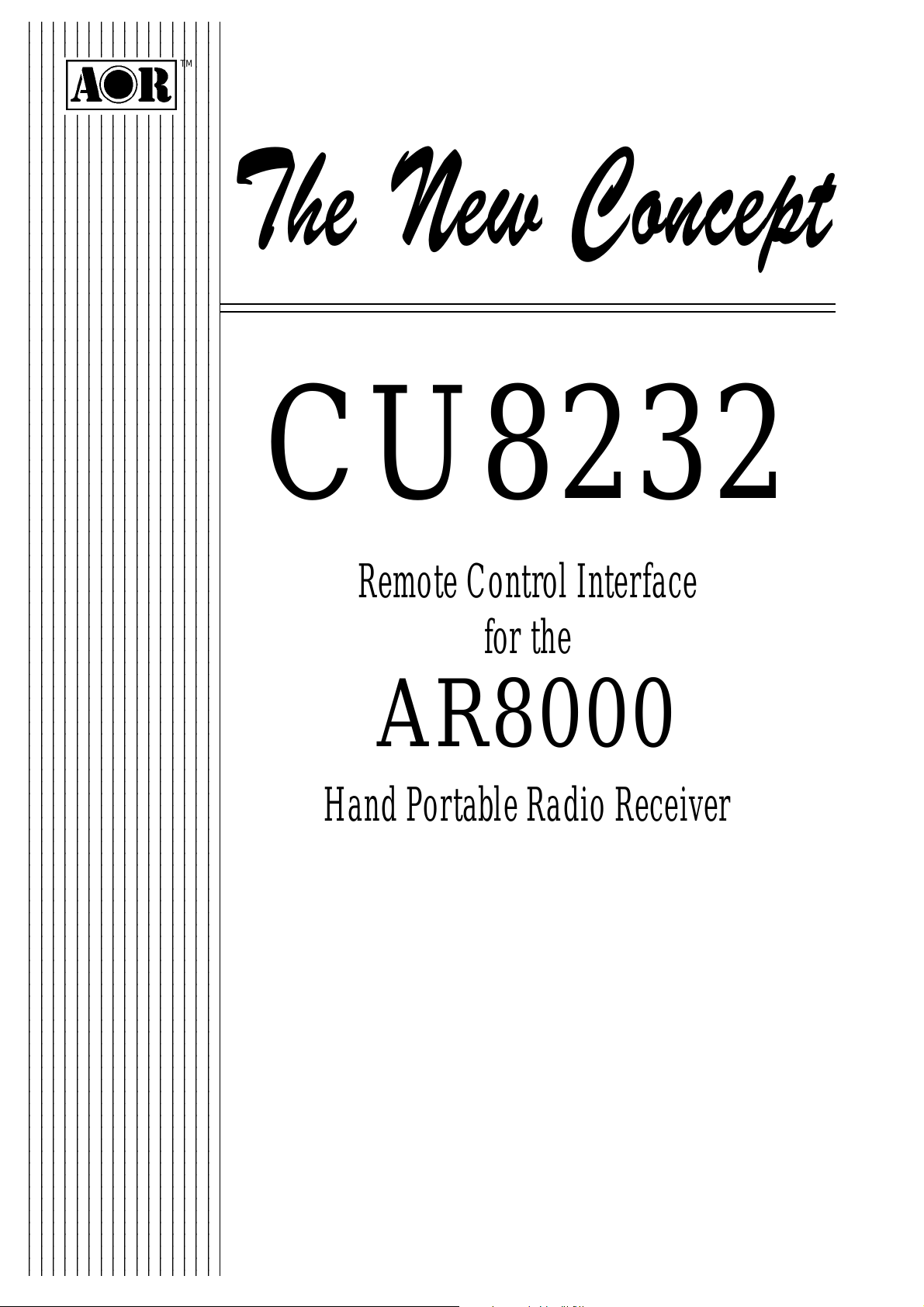
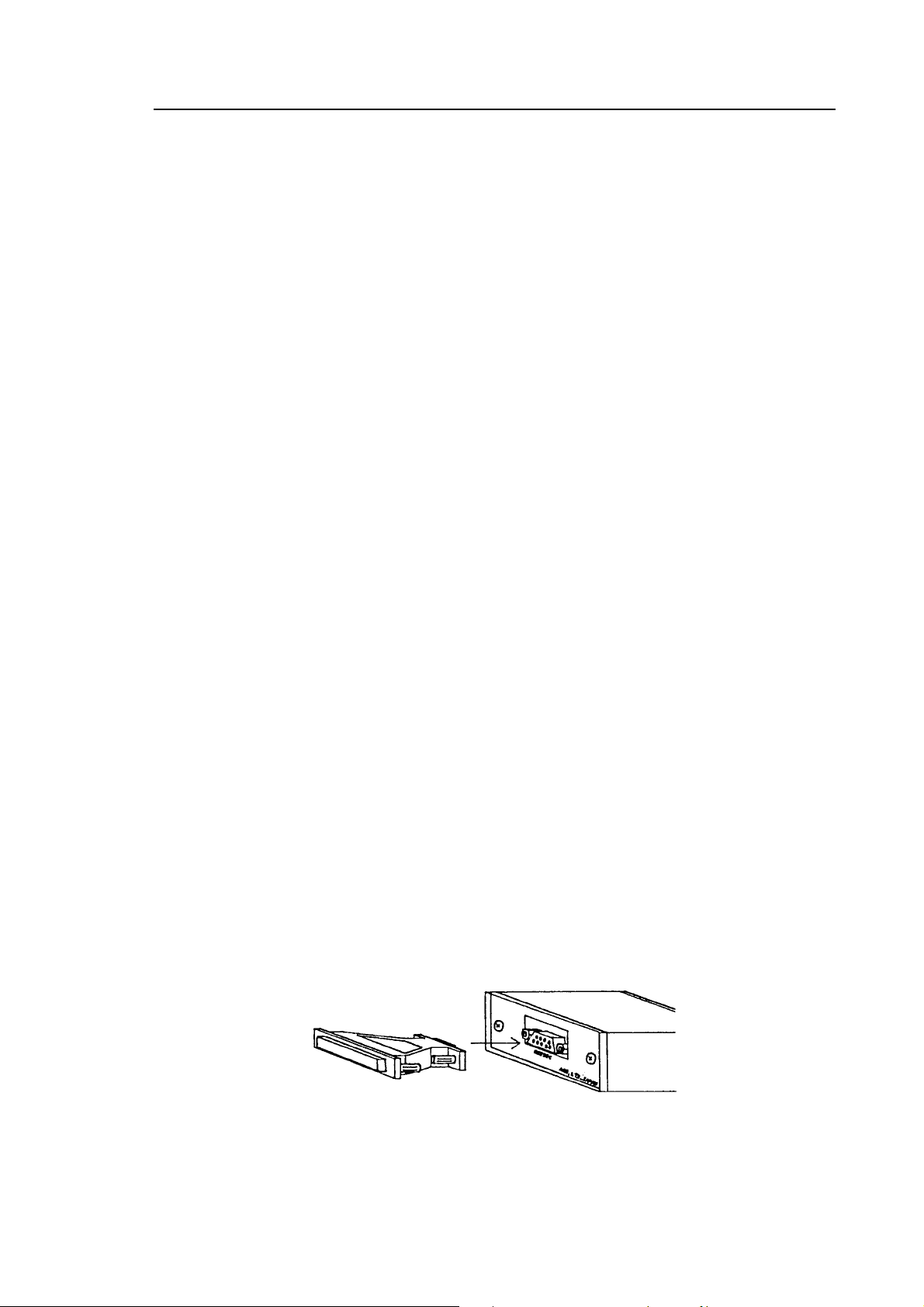
1. A ribbon cable is used to connect the AR8000 to the CU8232. One end of the
ribbon cable has a reinforced plate, this is used at the AR8000 end of the
connection. Insert one flat cable (they are both identical) into the CU8232
[PROGRAM] socket contact (metal) side downward.
General : Accessories : Connection & clone
- 4 -
Figure 1
The [PROGRAM] socket is the primary receiver connection used for computer
control. This port also takes power from the receiver (when the AR8000 is
switched On).
Should you wish to CLONE data between two AR8000 receivers, connect the
second ribbon cable to the socket labelled [COPY].
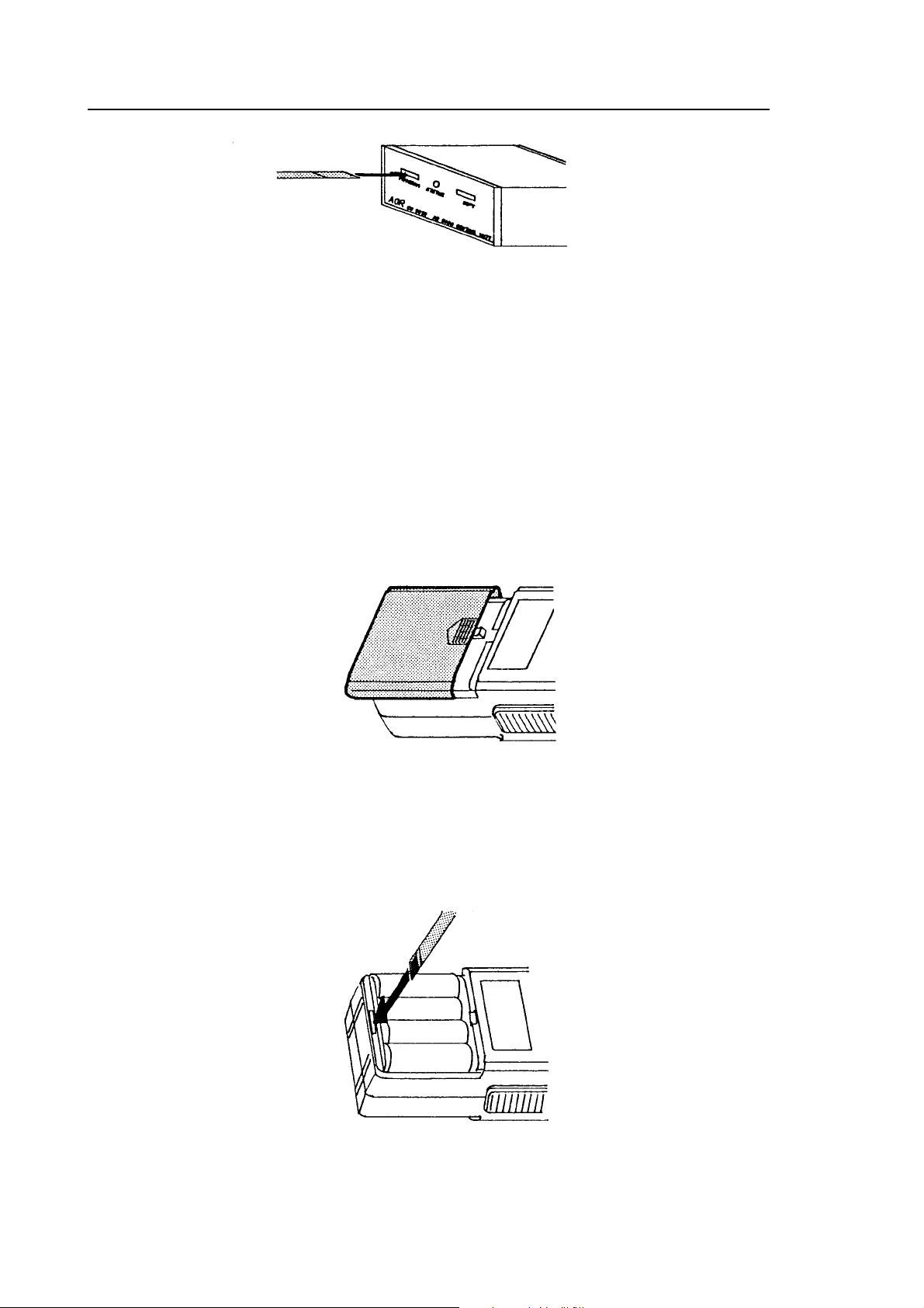
2. Remove the battery compartment lid of the AR8000 using a downward sliding
motion.
Figure 2
Locate the remote control socket which is located at the bottom edge of the
battery compartment. Insert the ribbon cable (with the reinforced plate) contact
(metal) side downward.
Figure 3
Connection & clone
- 5 -
It may be difficult to insert the flat cable into the CU8232 socket for the first time
as they are necessarily quite tight. If this is the case, try inserting with a little
upward pressure, it should become easier the next time. DO NOT APPLY
EXCESSIVE STRESS TO THE FLAT CABLE UNDER ANY CIRCUMSTANCES.
A DC voltage is fed to the CU8232 by the AR8000 connected to the [PROGRAM]
socket. When the receiver is switched On, the AR8000 DATA is routed to the
RS232 connector.
If a second receiver is connected to the [COPY] socket and switched On, the
CU8232 recognises it’s presence and routes data between receivers and not to
the RS232 socket.
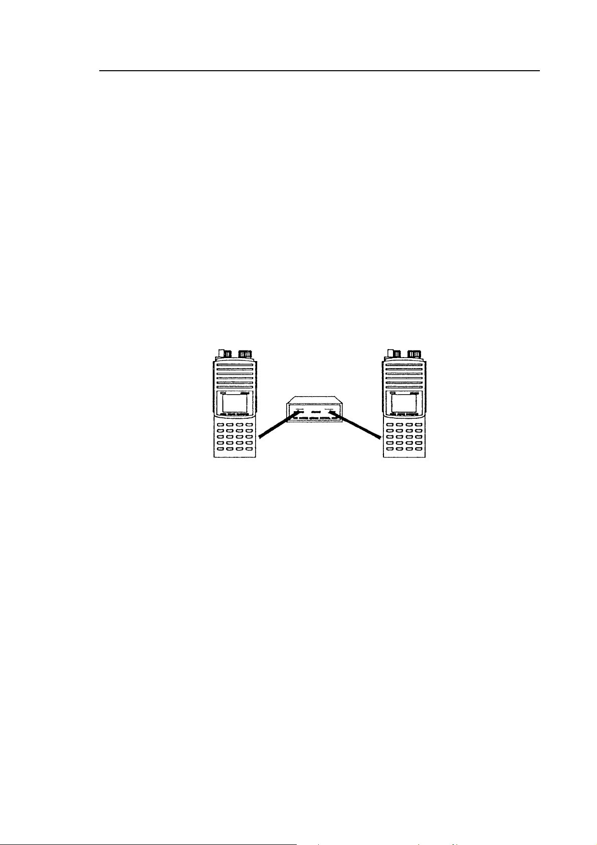
3. To CLONE data between two AR8000 receivers, connect each receiver to the
CU8232 using a ribbon cable as outlined above. Data may be transferred in
BOTH direction between the [PROGRAM] and [COPY] sockets.
Figure 4
4. Switch both receivers On and run the CLONE functions as detailed on page
102 section 19 of the English language operating manual.
Caution! Make sure that no low / flat batteries occur while the data clone is in
progress. Although no significant extra current is required for clone operations,
flat batteries may cause corrupted data transfer. It is advisable that the receivers
are both powered from their chargers (which were supplied with the receivers)
during clone operation.
5. If a data clone fails retry the procedures of clone operation after checking the
following:
¶ Make sure that all connections are correct and there is no loose contact.
¶ Ensure that one receiver is in TRANSMIT mode and the other is in
RECEIVE mode.
Connection & clone
- 6 -
¶ Always press the [ENT] key of the AR8000 in RECEIVE mode first so that
it is ready to accept data.
¶ Press the [CLEAR] key of the receiver prior to the retry if the failure is
due to incorrect connections or an error in key sequence.
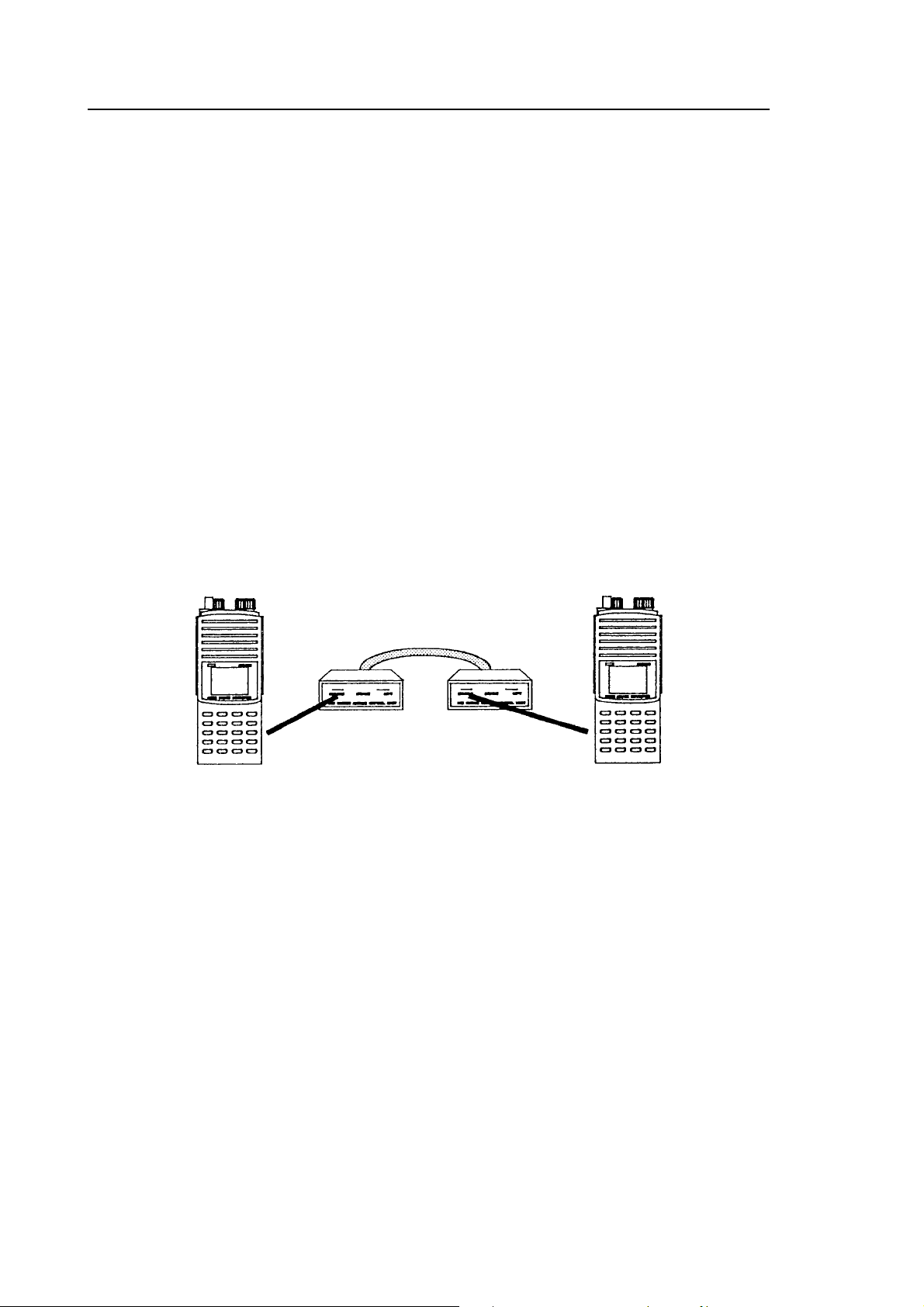
6. An alternative method may be used to connect two AR8000 receivers for data
CLONE. Two CU8232 interfaces may be employed with each AR8000
connected to the [PROGRAM] socket. The RS232 9-pin connectors are
linked using a three wire crossed cable:
CU8232 CU8232
Pin 2 Pin 3
Pin 3 Pin 2
Pin 5 Pin 5
No other pins are used.
Figure 5
(4) Connection for RS232 operation
The remote facility enables the AR8000 to be operated via a computer such as an
IBM-PC or similar, basic remote control terminal or dedicated software will be
required to address the AR8000 through the CU8232.
Switching the receiver On/Off, setting of volume and adjustment of squelch cannot
be achieved via the RS232 port.
Computers “always” generate RF noise which may interfere with the AR8000
reception if the standard helical rubber aerial is used. To reduce the effects of
noise, use of a remote aerial is highly recommended with good quality 50 OHM
coaxial cable employed.
Connection & clone : RS232
- 7 -
Connect the AR8000 to the [PROGRAM] socket of the CU8232 as outlined earlier
in section (3) and figure 1.
Connection to a computer is via the rear panel RS232C 9-pin “D” type female
socket. Should you require a male socket then a 9-pin gender changer is
supplied in the package. Should you prefer to use a 25-way “D” type female
socket, an adaptor is also supplied as standard.
Always use a straight RS232 cable (null modem is not to be used!). The RS232
cable should be of good quality and no more than 2m in length. As the CU8232 is
powered from the AR8000, excessive cable length may cause lost data between
the AR8000 and computer.
Connection for an IBM-PC or clone is as follows:
CU8232 9-PIN IBM-PC 9-PIN
22
33
5 5 (Ground)
All other pins not used but pins 4, 6 & 8 are linked together inside the CU8232.
Some software requires the linking of CTS/RTS at the computer end of the cable
(pins 7 & 8).
CU8232 9-PIN IBM-PC 25-PIN
23
32
5 7 (Ground)
All other pins not used but pins 4, 6 & 8 are linked together inside the CU8232.
Some software requires the linking of CTS/RTS at the computer end of the cable
(pins 4 & 5).
Figure 6
RS232 operation
- 8 -
(5) Communication parameters
Communication between the AR8000 and computer (via the CU8232) uses
semi-duplex. Refer to both the English language operating manual (page 101
section 18-1) and the computer handbook for correct settings.
Baud rate: 2400, 4800, 9600 selectable
Delimiter: CR or CR,LF selectable
Stop bit: 2 BIT
Parity check: None
The PC requires X-parameter flow control.
Both the computer and AR8000 must use the same parameters for correct
operation.
If data is regularly lost or corrupted, try using a slower speed such as 4800 or
2400 baud. Use of a slower baud rate should not greatly reduce overall
communications transfer rate since the processing time within the receiver and
PLL lock-time ultimately restricts the whole process.
Note: When changing BAUD rate, switch the AR8000 Off/On to
ensure the new speed is selected.
(6) Use of Microsoft WINDOWS “TERMINAL”
Assuming you have DOS and WINDOWS 3.1 (or later) loaded on an IBM-PC
compatible computer, WINDOWS “TERMINAL” may be used to address the
CU8232 and AR8000 receiver to enable basic remote operation.
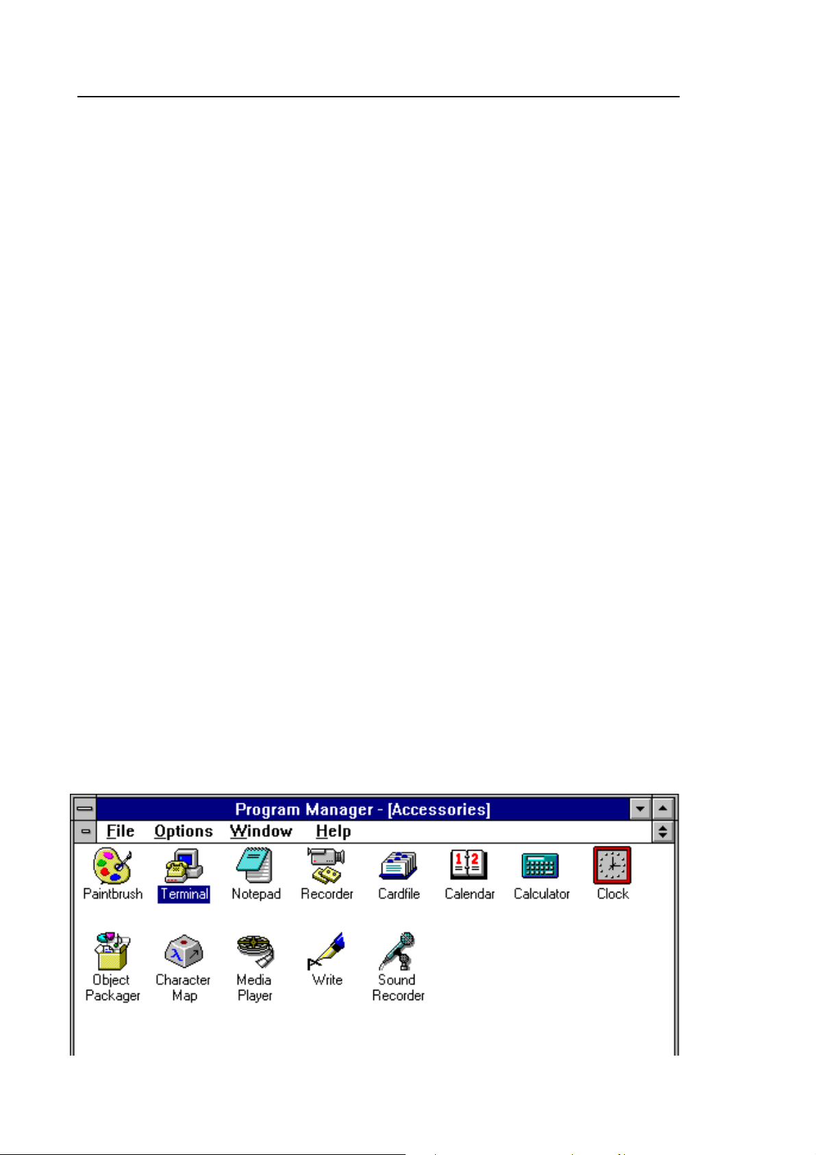
Start WINDOWS by typing WIN at the DOS prompt. Locate the [TERMINAL]
ICON in the program manager ACCESSORIES group and double-click.
Figure 7
Communication parameters : WINDOWS TERMINAL
- 9 -
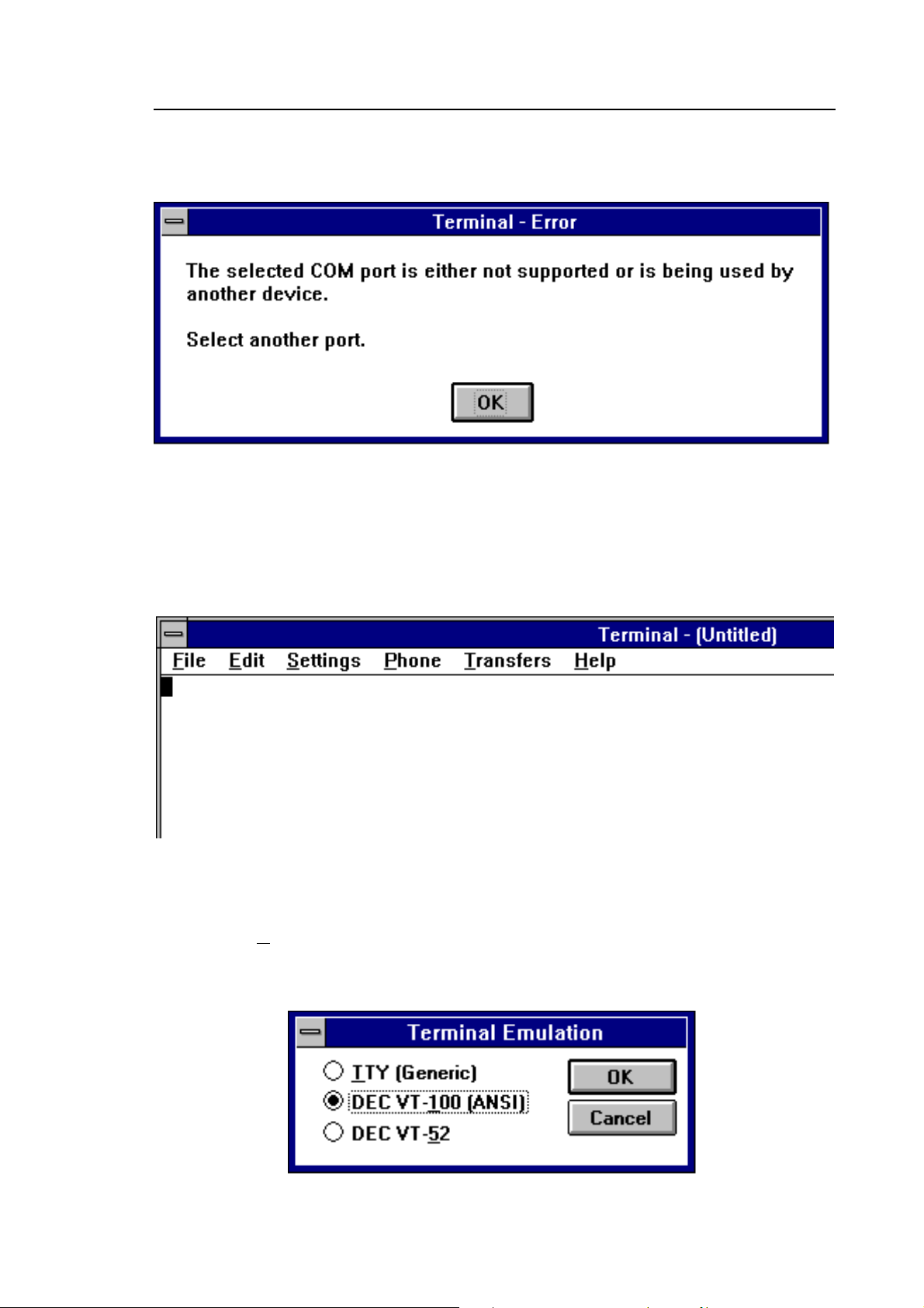
If the terminal program has not be configured an error message will appear
(depending upon the serial port / mouse configuration). Click on [OK] to continue.
Figure 8
TERMINAL will open and appear on the screen. You may re-size or maximise the
screen at this point.
Figure 9
Click on the Settings heading toward the top of the screen so that the
communications and terminal parameters may be configured. Click on
“TERMINAL EMULATION” then select “ANSI” then click on [OK].
Figure 10
WINDOWS TERMINAL
- 10 -
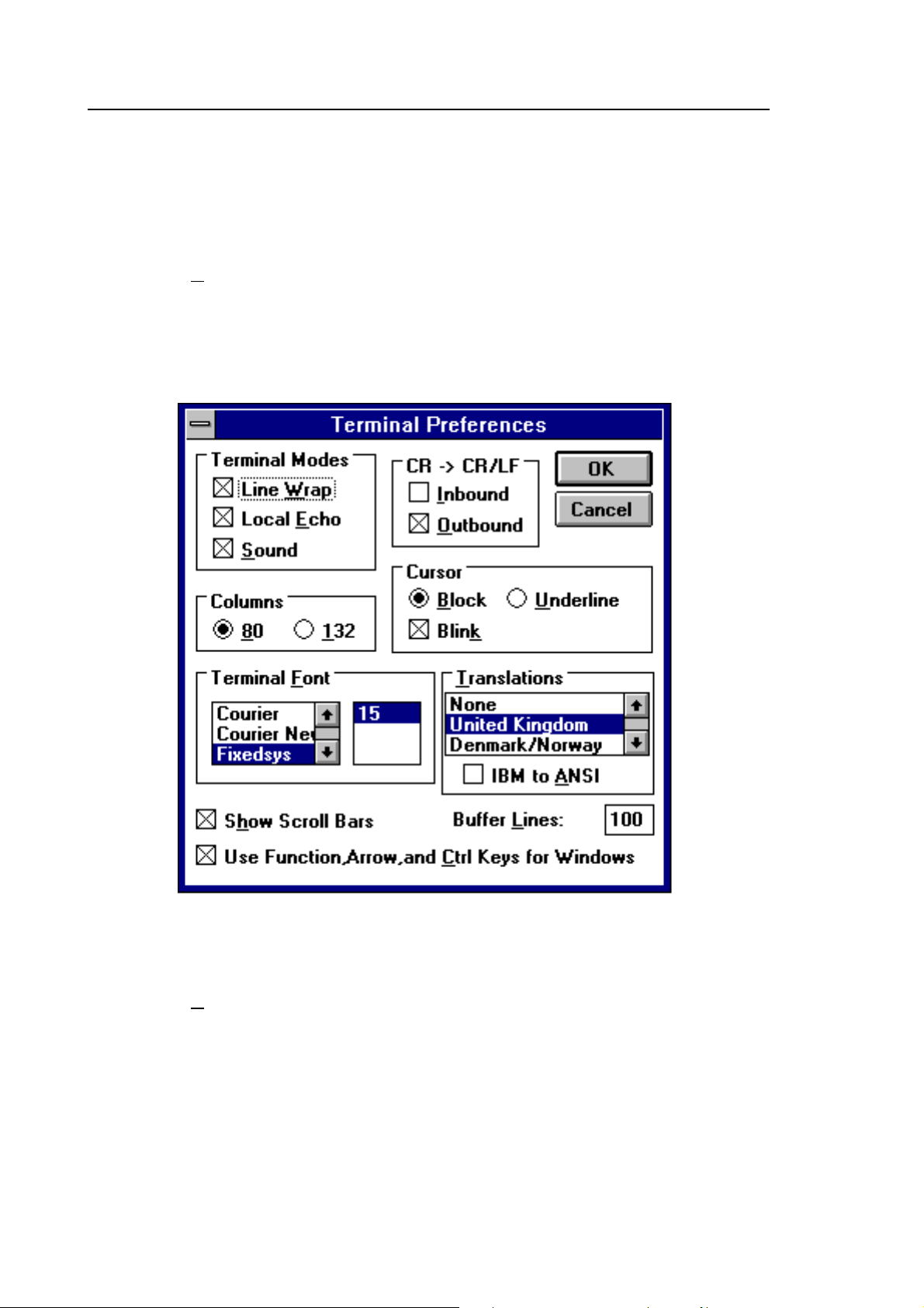
Click on the Settings heading toward the top of the screen so that the
communications and terminal parameters may be re-configured. Click on
“TERMINAL PREFERENCES” then select the options as shown in figure 11.
Finally click on [OK].
Figure 11
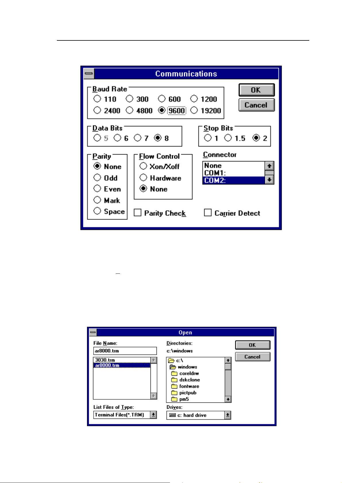
Click on the Settings heading toward the top of the screen so that the
communications and terminal parameters may be re-configured. Click on
“COMMUNICATIONS” then select the options as shown in figure 12. The choice
of COM port (COM1, COM2 etc) will depend upon your computer serial port and
mouse configuration. Finally click on [OK].
WINDOWS TERMINAL
- 11 -
Figure 12
Finally click on the File heading toward the top of the screen and select
SAVE_AS. This will enable the chosen parameters to be saved in a file which
may be OPENED next time TERMINAL is selected so that the parameters will not
require future re-configuration. Figure 13 shows a file name of AR8000.TRM,
(.TRM being the default extension). The file is saved in the main WINDOWS sub
directory.
Figure 13
WINDOWS TERMINAL

- 12 -
¶ For further information regarding WINDOWS TERMINAL and configuration,
please refer to the operating manual supplied with Microsoft software and
the computer.
Click on “COMMUNICATIONS” then select the options as shown in figure 11.
The choice of COM port (COM1, COM2 etc) will depend upon your computer
serial port and mouse configuration. Finally click on [OK].
(7) How to send a command
Each command comprises of two upper case letters (header) along with options
as required. All commands use ASCII code which MUST BE IN UPPER CASE
(except for the “ARROW” é ê which uses the control code of ASCII).
A multiple command entry is only valid where specified. Where a multiple
command entry is allowed, each command MUST be separated with a space
“h20” (HEX DECIMAL).
Each command is completed with a [CR] or [CR],[LF] whichever is specified in the
AR8000 receiver configuration (page 101 section 18-1 of the English language
AR8000 operating manual), thereafter described as [ï].
Although there is no local echo, either [ï] or a specified response should come
back from the receiver after confirming the correct command.
A space is often shown as "_" in the following examples.
REMOTE indication
When the AR8000 has received a command via the RS232C port the receiver’s
LCD with alternate between the top line of data and the wired “REMOTE”. When
remote mode is engaged the receiver’s keypad becomes inoperative. To restore
operation to the receiver’s keypad press [LOCAL] - effectively remote operation is
cancelled. Remote mode is re-engaged when a new command is received via the
RS232C port.
The receiver always acknowledges the receipt of a command by sending [ï]
(as specified in the receiver configuration) or will respond with the requested data.
Only send a second command after the first command has gained a response.
If no response has been gained after a short while, the receiver has failed to
receive the command properly. Send a [ï] then re-send the command. Should
problems persist, check your serial / CU8232 connections and try reducing the
RS232 baud rate.
Sending a command

- 13 -
(8) List of commands
Application Command
VFO Freq Input RF VA VB
Receiver Function AT AU MC MD RX ST
SQ, S-Meter LC LM MG SG
Receive Mode DD MR MG MS SG SM SS VF
Search BN BQ BS SA SB SD SE SG SO SP SQ SR SS
Search Data Write AT AU MD SE SL SU ST TT
Pass Freq PD PR PS PW
Memo CH, Scan BM BN MA MG ML MP MQ MR MS XA XB XD XM
XO XP XQ
Memo CH Data Write AT AU MD MX RF ST TM
Select Scan GA GD GR SM
Others EX PA PI SC SI SN TI
é[UP] (1E) ê[DOWN] (1F) ( )= Hex Decimal
Arrow is a control code of ASCII.
No delimiter is required when sending Arrow.
Commands which have dual roles are duplicated in
this list.
List of commands

- 14 -
(9) Command index
AT Register the attenuator position ON/OFF.
AU Register the auto mode ON/OFF.
BM Register the scan bank link ON/OFF.
BN Change the search/scan bank.
BQ Register the search bank link function ON/OFF.
BS Register the search bank link ON/OFF.
DD Recall the VFO mode.
EX End the Remote mode (RS232C).
GA Register the select scan channel from Memory channel.
GD Delete the select scan channel from Memory channel.
GR Recall the select scan channel.
LC Respond with the received freq and S-level when SQ opens.
LM Respond with the S-level reading and SQ open/close.
MA Respond with the contents of the present bank or specified
bank.
MC Select the monitor switch position.
MD Select the receive mode.
MG Start the scan mode. Respond with receive freq and S-level
reading when SQ is open (as LC).
ML Register the scan bank link function ON/OFF.
MP Register the present memory channel as Pass channel.
MQ Delete the present bank or memory channel.
MR Switch to the memory read (M.RE) mode.
MS Switch to the scan (SCAN) mode.
MX Write data into memory channel.
PA Register the delay time of Power Save mode.
PD Delete the Search Pass Freq
PI Register the interval time of Power Save mode.
PR Recall the Search Pass Freq
PS Register the Search Pass Freq
PW Register the presently receiving freq as Pass Freq
RF Key in the Freq in VFO
RX Respond with the presently receiving data
SA Register the Audio Search ON/OFF.
SB Register the Level Search ON/OFF. Set the S-level.
SC Change the operating code of the option unit (when fitted - not
available in the UK).
SD Change-over HOLD/DELAY in Search mode. Register the delay
time.
Command index

- 15 -
SE Register the Search data.
SG Start the Search mode. Respond with freq and S-level reading
when SQ is open.
SI Switch the option unit ON/OFF (when fitted - not available in the
UK).
SL Write the start freq of Search.
SM Start the Select Scan.
SN Write the Pass Word. Recall the Pass Word.
SO Recall the Search operating mode.
SP Register the Free Search ON/OFF and delay time.
SQ Check the SQ setting.
SR Recall the Search data.
SS Start the Search.
ST Register the step size in search mode.
SU Register the end freq of search mode.
TI Register the interval time of Priority channel.
TM Write the text for memory channel
TT Write the text for search bank
VA Initiate the AVFO mode.
VB Initiate the BVFO mode.
VF Initiate the 2VFO mode.
XA Register the Audio Scan ON/OFF.
XB Register the Level Scan ON/OFF.
XD Register the delay time in Scan mode.
XM Register the Mode Scan ON/OFF.
XO Recall the Free Scan operating mode.
XP Register the Free Scan ON/OFF and timing.
XQ Recall the SQ operating mode.
Arrow Mark
é[UP] ê[DOWN] similar to the receiver’s keyboard.

- 16 -
(10) Explanation of commands
AT
ATTENUATOR ON/OFF.
ATn[ï] n = 0 ATT OFF
n = 1 ATT ON
Multiple commands in conjunction with other commands are possible with a space
in between: AT, AU, MD, RF, ST, VA, VB.
Example: AU0_MD3_RF145.2_AT1[ï]
AT[ï] checks the current attenuator setting, the response being:
AT0 = ATT OFF
AT1 = ATT ON
Related commands MD MX RF SE VA VB
AU
AUTO MODE (and step) ON/OFF.
AUn[ï] n = 0 AUTO MODE OFF
n = 1 AUTO MODE ON
Multiple commands in conjunction with other commands are possible with a space
in between: AT, AU, MD, RF, ST, VA, VB.
Example: AU0_MD3_RF145.2[ï]
AU[ï] checks the current auto mode setting, this is not valid when “M.RE” or
“SCAN” is in use. The usual response to the AU request being:
AU0 = AUTO MODE OFF
AU1 = AUTO MODE ON - step size and receive mode set automatically.
Related commands MD MX RF SE ST VA VB
Explanation of commands : AT : AU
 Loading...