


 Loading...
Chapter 0 Catalogue
Chapter 0 Catalogue........................................................ |
0-1 |
|
Chapter 1 How To Use This Manual....................... |
1-1 |
|
1.1 A Thank-you Note Before You Get Started ......................................................................... |
1-1 |
|
1.2 The Features Of This Manual ............................................................................................. |
1-2 |
|
1.3 |
Preliminary Tools ................................................................................................................ |
1-3 |
Chapter 2 Start To Assemble...................................... |
2-1 |
|
2.1 |
Open The Housing.............................................................................................................. |
2-1 |
2.2 |
Check Accessories ............................................................................................................. |
2-3 |
2.3 |
Check Your I/O Back-panel................................................................................................. |
2-5 |
2.4 |
Set Up Hard Disk ................................................................................................................ |
2-7 |
2.5 |
Set Up Motherboard ........................................................................................................... |
2-9 |
2.6 |
Set Up CPU ....................................................................................................................... |
2-11 |
2.7 |
Plug In Memory................................................................................................................. |
2-18 |
2.8 |
Set Up Front USB / Audio Module (Optional) ................................................................... |
2-20 |
2.9 |
Set Up Floppy Diskette Drive............................................................................................ |
2-22 |
2.10 Set Up Optical Storage Devices ..................................................................................... |
2-24 |
|
2.11 Connect Signal Cable ..................................................................................................... |
2-27 |
|
2.12 Connect Power Cord ...................................................................................................... |
2-30 |
|
2.13 Connect The Front Panel LEDs...................................................................................... |
2-33 |
|
2.14 Set Up Interface Card ..................................................................................................... |
2-34 |
|
2.15 All Set.............................................................................................................................. |
2-37 |
|
Catalogue 0-1

Chapter 3 Check What You've Achieved..3-1
3.1 |
Connect The External Peripherals...................................................................................... |
3-1 |
3.2 Turn On The Power To Check............................................................................................. |
3-5 |
|
3.3 |
Postscripts .......................................................................................................................... |
3-9 |
0-2 How To Use This Manual

Chapter 1 How To Use This Manual
1.1 A Thank-you Note Before You Get Started
First of all, we would like to express our gratitude to your purchase of this specially-designed bare-system by AOpen. Once again, this bare-system is designed uniquely to meet all your personal needs with our great industrial designing ability and our everlasting perseverance with the quality of all products.
This manual is for those who want to set up the computer by themselves. In other words, this is a book for " Fresh drivers on the road." If you are already a veteran, this manual may not be that suitable for you. It is our hope that the novices can build up their own computers step by step.
Now, we invite you to personally experience this user-friendly manual and all the powerful functions this AOpen Baresystem offer.
The logos of Adobe and Acrobat are the registered trademarks of Adobe Systems Incorporated.
The logos of AMD, Athlon, and Duron are the registered trademarks of Advanced Micro Devices, Inc. The logos of Intel, Intel Celeron and Pentium II&III are the registered trademarks of Intel Corporation.
The logos of Microsoft, Windows are the registered trademarks of Microsoft Corporation in America and other countries.
All the titles of the products and the trademarks mentioned in this manual are for the purpose of illustrative conveniences and are possessed by their respective firms.
We regret not informing about any changes in usage standards and other related information. AOpen Company reserves the right of altering or modifying the content of this manual. In case of any mistakes or incorrect descriptions, which include those on the products, AOpen makes no guarantee or commitments.
This document is based on the copyright laws in order to protect our company and reserve all rights.
Under no circumstances are any types of duplicating and loading this brochure in any databases and media permitted except the permission signed on formal document by AOpen Company.
1996-2000 Copyrights, AOpen Ltd. All rights reserved. http://www.aopen.com
How To Use This Manual 1-1
1.2 The Features Of This Manual
In this manual, you will be able to know how to:
Set up a personal computer on your own.
Correctly and safely put everything together and get some ideas about hardware. Make the setup easier with some practical techniques.
In addition, this manual DOES NOT offer you:
Any sorts of back doors, such as overclocking.
A great bunch of hardware standard that is difficult to understand.
Lengthy, fanciful but vague theories.
Instead, this manual explains theories in simple language by colorful illustrations. Therefore, you will see the icons below quite often.
Note
Contains knowledge you should know in process of assembling and some helpful tips.
 Warning
 Setup Order
 Force direction
When seeing this mark, please beware. It highlights mistakes occurred often when assembling or something you should pay attention to.
This mark indicates the assembling sequence which should be followed by numerical order.
This arrow shows the right direction the force should be imposed or the correct assembling direction.
1-2 How To Use This Manual
1.3 Preliminary Tools
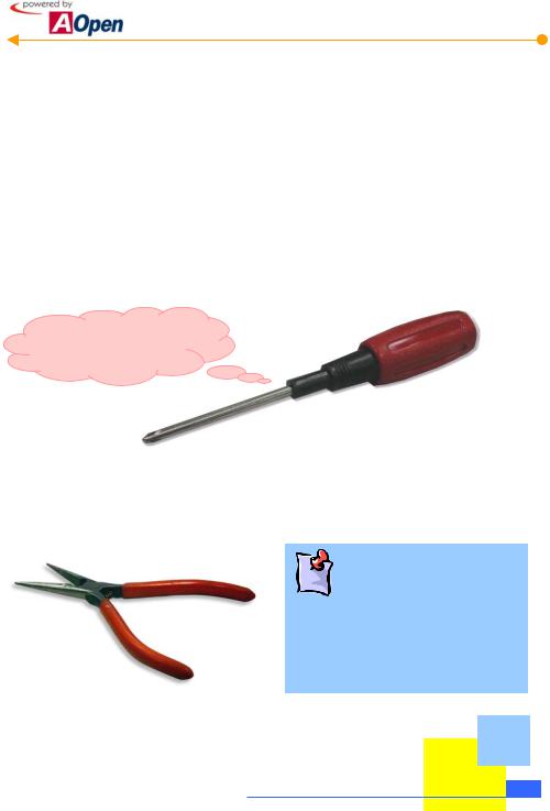
"A workman must first sharpen his tools if he is to do his work well". Before you start the setup, there are some tools that you can't spare.
Firstly, the most frequently used tool is cross screwdriver. You can use it to screw most interior components. A suitable screwdriver can make the setup job much easier. But does any screwdriver apply? No, we suggest a screwdriver with a magnetic tip. When you set up your PC, the situation is very likely to happen: you accidentally drop screws into the space between components. In case of this, a magnetic screwdriver helps attracting those fallen screws that are impossible to reach by hands. Some screw holes are difficult to reach. At this case, we need a magnetic screwdriver as well. In addition, the size of tool does matter. Generally, the domestic 107 cross screwdriver is the best one.
I can get it done!!
When putting things together, you can't avoid adjusting Jumpers. In most of cases, it can be done barehanded. But the time always comes when there is a situation hands fail to reach in and fix the problem. You will thank God if you have a pliers on hand to avoid any hassle just because of one JUMPER.
What is Jumper?
Jumper is something generally referred to " Jumping wire", which is used to adjust some functions such as FSB (front side bus), ratio, and sound switches adjustment by causing them short circuit.
How To Use This Manual 1-3
[Note]
1-4 How To Use This Manual
Chapter 2 Start To Assemble
2.1 Open The Housing
This product you bought from AOpen Baresystem series belongs to special standards of MicroATX / ATX. And this bare-system has following distinguishing features:
The MicroATX/ATX housing provides you a big space to expand capacity.
Bend-in edges ensure your safety when assembling.
 A highly efficient 300/250W power supplier ensures your computer work smoothly in most cases.
FCC Class B / DoC and CE conformed standards guarantee your health.
A high-efficiency motherboard attached makes your job much easier.
Led cover provides 4 kinds of option colors.
A great extensible function; you can optionally purchase AGP/PCI interfaces, VGA or other add-on cards.
P4 ready
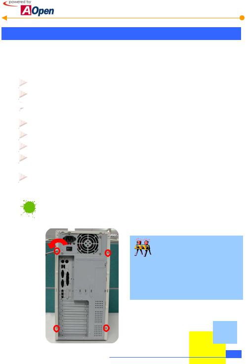
Now, let's open the housing and take a look at the interior design and attached accessories:


 Loosen screws on the housing
You can loosen them with a cross screwdriver.
Need your attention.
This manual can be applied to HQ / LX / HX series Baresystem. They are only different in their appearance. The pictures shown below are just for your reference.
Start To Handle 2-1
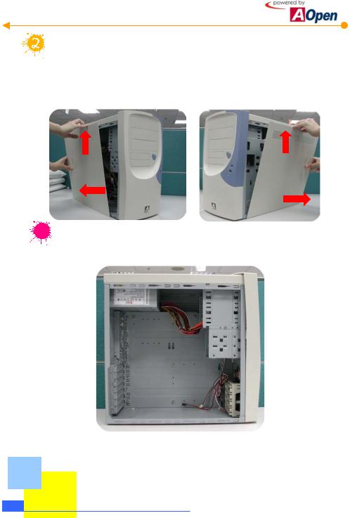
Remove both sides of housings.
To remove side housings, slide the housing a bit backward and lift it up. Procedure goes the same with the other side..


 Then you can have a clear look of AOpen Baresystem.
2-2 Start To Handle
2.2 Check Accessories
Opening the housing, you are supposed to see the following accessories:
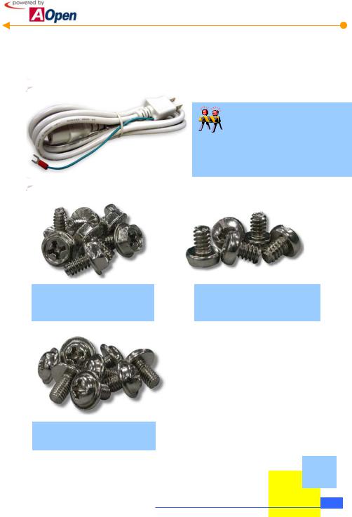
 Power cord: Connects the computer power.
Are power cords all the same?
Power cords are various in different countries. Please use an appropriate power cord according to your country.
 Fixed screws: After opening the accessory parcel, you'll see three different types of screws as follows:
As shown in the picture, the threads on NO.1 screw are wide and it is a so-called hex screw.
As shown in the picture, the NO.2 screw’s threads are wide as well but it has a round head. It is a so-called binding head screw.
As shown in the picture, threads on NO.3 screw are narrow. It is a so-called round head washer screw.
Start To Handle 2-3
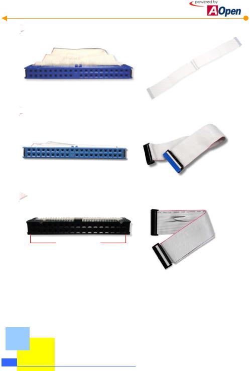
 IDE Cable: is a 40-pin connector used to link IDE interface devices such as hard disk and CD-ROM.
 40-Pin Connector
 IDE Cable: a 80-pin connector to connect the hard disk with IDE interface and CD-ROM.
 80-Pin Connector
Floppy diskette Drive (FDD) Cable: is a 34-pin connector to connect disk drive.
34-Pin Connector
2-4 Start To Handle
2.3 Check Your I/O Back-panel
HQ / LX /HX series Baresystem is equipped with an all-purpose I/O back-panel. You can break through the port bracket according to your personal needs. If your motherboard has built-in sound effects or network functions, then you need more ports to connect external speakers and network.
Check I/O connector ports on the motherboard with your housing and decide which port brackets you need to break through.
If there is a built-in network card on the 
 motherboard, then you need to break
through this bracket.
If there is a built-in sound device, then  you need to break though these two
brackets.
Start To Handle 2-5
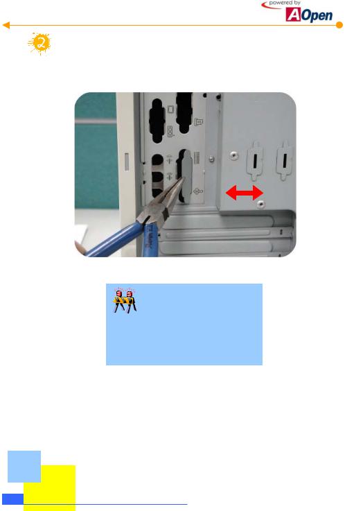
Use a tool to break the iron bracket on the I/O back-panel.
As shown in the picture, use a tool to tear down the bracket by twisting it several times.
Be careful when twisting!!
When breaking brackets, it is wise to use a pliers to avoid cutting yourself. If you fail to have a pliers on hand, pad a piece of cloth on your palm to tear it down.
2-6 Start To Handle

2.4 Set Up Hard Disk
A Hard disk is the place where most of the data is stored. Therefore, it is one of the most important components in a personal computer. This section will introduce you the knowledge of the hard disk and some important tips when you set it up.
Get to know the hard disk
Taking out the hard disk from the parcel, you will see the following equipment:
Jumper configurations
Adjust Jumpers on your hard disk
As has been mentioned to you, we assume you know the definition of Jumpers. The setting of Jumpers in IDE hard disk is essential for a computer to distinguish various devices connected on the same cable. To be general, we normally set the hard disk to "Master", indicating the first device of the cable; and we set CD-ROM to "Slave", meaning the second device of the cable. The Jumper settings are marked on the tag affixed to the surface of the hard disk or mentioned in its handbook. Here we only set up one hard disk so that it has to be set as "Master."
|
|
Jumper here is |
|
|
IDE cable connector |
set as Power connector |
|||
|
|
"Master" |
||
Start To Handle 2-7
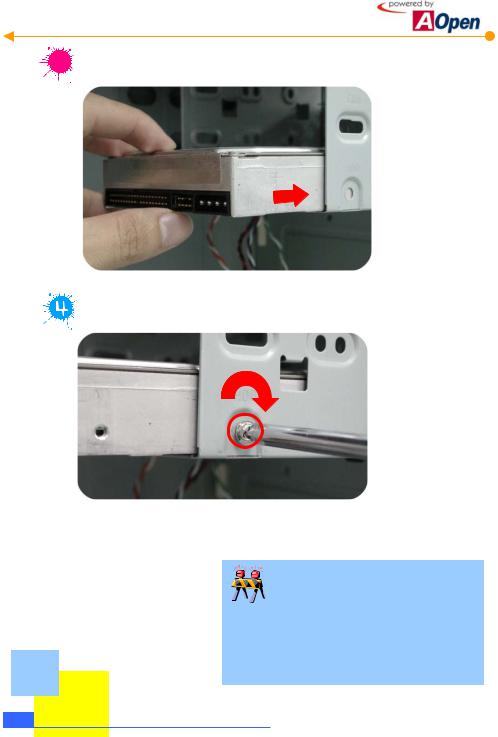


 Place the hard disk into the frame.
Tighten the screws to the frame.
In fact, a hard disk is a very fragile and delicate device though it is covered with a metal housing. When in operation, a slight vibration might do great harm. Therefore, be sure to screw it on the frame securely.
Don't mess up screws!!
Generally there are special screws for a hard disk in the parcel when you buy a new hard disk. If no screws are attached, use those packed in the accessory parcel. Make sure to use the NO.2 screws. (See page 2-3)
2-8 Start To Handle
2.5 Set Up Motherboard
It is very easy to set up a motherboard in AOpen Baresystem. Just place the motherboard in the correct position and tighten the screws. Please follow the steps below:
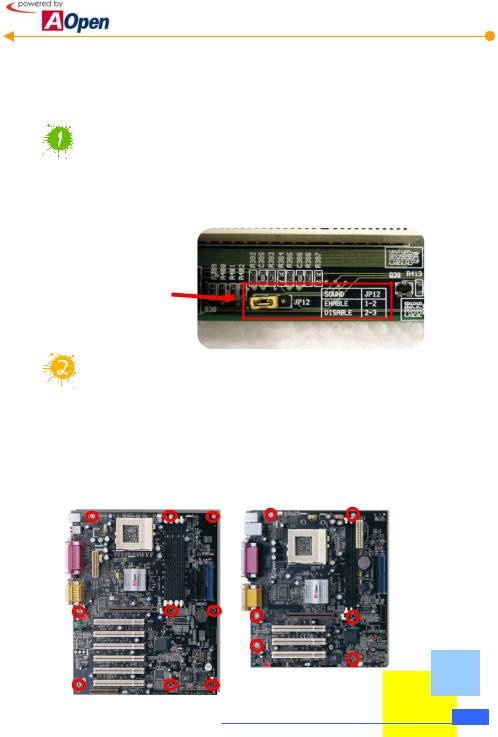
Read the handbook of the motherboard and adjust Jumper settings.
Currently almost all motherboards have a Jumper-free design (or Jumperless design). Even so, there are still some other functions that need to be adjusted through Jumpers. Please refer to the handbook of your motherboard and adjust the Jumper settings according to your personal requirements.
Please refer to your motherboard handbook to adjust the Jumper settings according to your needs.
How many brass studs should I screw?
Before setting up the motherboard, you have to screw brass studs at the chassis of housing to avoid the motherboard from directly contacting with the iron base. For your convenience, we have fastened 7 brass studs on HQ / LX / HX series Baresystem. Please compare your motherboard with your housing. Then just screw the brass studs you need. The Motherboard you purchase may look different from the one shown below.
ATX Model |
Micro ATX Model |
Start To Handle 2-9

How many brass studs should I screw?
There are holes for screws on the motherboard. Just compare the position of the holes with the iron base of the housing. Then you will know the position where to screw the brass studs. The number of the brass studs depends on the motherboard you purchased.
With an angle of 45 degrees, level the motherboard at the back panel brackets  and place it on the brass studs you just screwed.


 Tighten the screws respectively with screws NO.1
2-10 Start To Handle
2.6 Set Up CPU
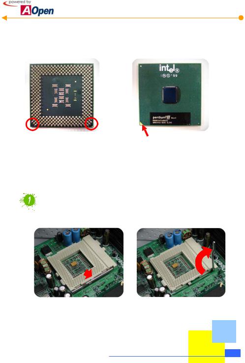
When setting up CPU, please don't go wrong with the direction of CPU. It is very easy to distinguish its direction. First of all, let's have a look at what CPU is like:
Note that the arrow indicates the first pin
As shown in the picture, it's FC-PGA CPU of Intel Pentium III, which is so-called Socket370 CPU. There are still many other varieties of CPU available in the marketplace. Please pay attention to the model when you are purchasing. It should be consistent with your motherboard. What we use here is an Intel’s Pentium III CPU. You need not worry if you are not using the same one as all models have similar set-up procedures.
Pull open the lever next to the CPU socket to 90 degrees.
Pull outward the lever beside the CPU socket and pull it upward vertically.
Start To Handle 2-11
Loading...