


Chapter 2
Hardware Installation
This chapter gives you a step-by-step procedure on how to install your system. Follow each section accordingly.
Caution: Electrostatic discharge (ESD) can damage your processor, disk drives, expansion boards, and other components. Always observe the following precautions before you install a system component.
1.Do not remove a component from its protective packaging until you are ready to install it.
2.Wear a wrist ground strap and attach it to a metal part of the system unit before handling a component. If a wrist strap is not available, maintain contact with the system unit throughout any procedure requiring ESD protection.
2-1

Hardware Installation
2.1Jumper and Connector Locations
The following figure shows the locations of the jumpers and connectors on the system board:
|
USB |
|
|
KBC |
|
Super |
|
|
KB1 |
|
|
|
|
|
|
|
|
PS2 MS |
|
|
|||
|
|
|
|
|
|
I/O |
|
|
|||
|
|
|
|
|
|
|
|
|
|
|
|
I |
I |
I |
|
|
|
|
|
|
|
|
|
S |
S |
S |
|
|
|
|
|
|
COM2 |
|
|
A |
A |
A |
PCI |
PCI |
PCI |
PCI |
|
|
|
|
|
3 |
2 |
1 |
4 |
3 |
2 |
1 |
|
|
|
|
|
|
|
|
|
|
|
FDC |
|
|
COM1 |
|
|
|
|
|
|
|
|
PWR1 |
|
|
|
PRINTER |
|
|
|
|
|
|
|
|
|
|
|
|
|
|
|
|
|
|
|
IDE1 |
|
|
|
|
|
|
|
|
|
|
|
IDE2 |
|
|
|
D |
D |
|
|
|
|
|
|
|
|
|
|
||
|
|
|
|
|
|
|
|
|
|
I |
I |
|
|
|
|
|
|
S |
S |
S |
S |
M |
M |
|
|
|
|
|
|
M |
M |
||||
|
|
|
|
|
|
I |
I |
I |
I |
1 |
2 |
|
|
|
|
|
|
M M M M |
|
|
|||
|
|
|
|
|
|
M M M M |
|
|
|||
|
|
|
|
|
|
1 |
2 |
3 |
4 |
|
|
|
|
|
|
PiiX4 |
|
|
|
|
|
|
|
|
|
|
|
|
|
TX |
|
|
|
|
|
|
|
|
JP14 |
|
|
|
|
|
|
|
|
|
|
|
JP18 |
|
|
|
|
|
|
|
|
BIOS |
|
JP20 |
|
|
|
|
|
|
|
|
|
|
|
|
|
|
|
|
|
|
|
||
|
FAN |
|
|
|
|
|
|
|
|
|
|
|
JP11 |
|
|
|
|
|
|
|
|
|
|
|
HDD LED |
|
|
|
|
|
|
|
|
|
|
IrDA |
|
|
|
|
|
|
|
|
|
|
|
|
PANEL |
|
|
|
|
|
|
JP6 |
JP4 |
JP5 |
|
|
JP3 |
|
JP1 |
|
JP2 |
|
|
|
|
|
|
2-2 |
|
|
|
|
|
|
|
|
|
|
|

|
Hardware Installation |
Jumpers: |
|
JP1,JP2,JP3: |
CPU frequency ratio |
JP4,JP5,JP6: |
CPU external (bus) clock |
JP11: |
CPU core voltage setting (Vcore) |
JP14: |
Clear CMOS |
JP18: |
Onboard Super I/O enable/disable |
JP20: |
Onboard PS/2 mouse enable/disable |
Connectors: |
|
KB1: |
AT keyboard connector |
PWR1: |
AT (PS/2) power connector |
PS2 MS: |
PS/2 mouse connector |
USB: |
USB connector |
COM1: |
COM1 connector |
COM2: |
COM2 connector |
FDC: |
Floppy drive connector |
PRINTER: |
Printer connector |
IDE1: |
IDE1 primary channel |
IDE2: |
IDE2 secondary channel |
FAN: |
CPU fan connector |
IrDA: |
IrDA (Infrared) connector |
HDD LED: |
HDD LED connector |
PANEL: |
Front panel (Multifunction) connector |
2-3
Hardware Installation
2.2Jumpers
Jumpers are made by pin headers and plastic connecting caps for the purpose of customizing your hardware. Doing so requires basic knowledge of computer hardware, be sure you understand the meaning of the jumpers before you change any setting. The onboard jumpers are normally set to their default with optimized settings.
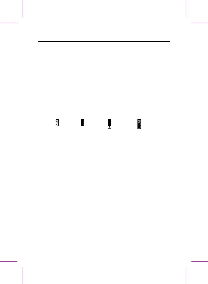
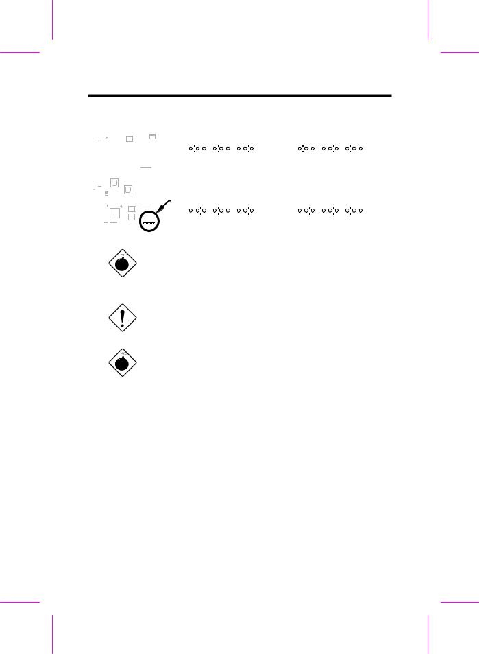
On the mainboard, normally there is a bold line marked beside pin 1 of the jumper, sometimes, there are numbers also. If we connect (short) plastic cap to pin 1 and 2, we will say set it at 1-2, and when we say jumper is open, that means no plastic cap connected to jumper pins.
1 |
1 |
1 |
1 |
2 |
2 |
2 |
2 |
|
|
3 |
3 |
Open |
Short |
Jumper set at 1-2 |
Jumper set at 2-3 |
|
|
2-4
Hardware Installation
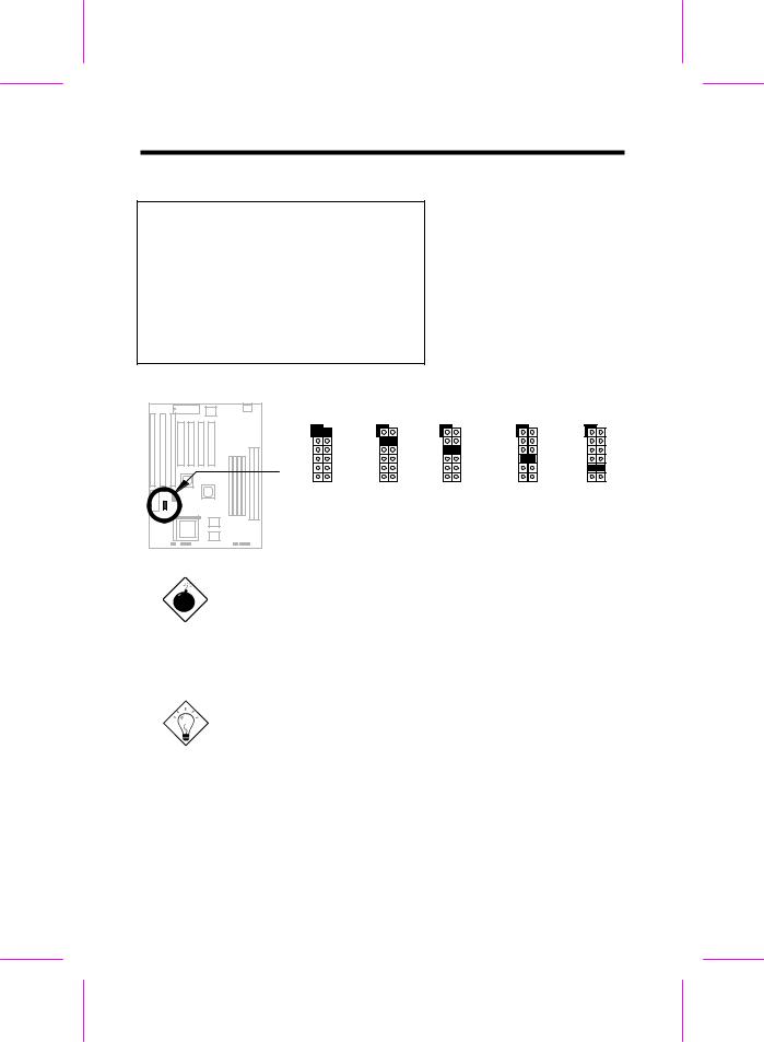
2.2.1 Setting the CPU Voltage
JP11 CPU Core Voltage (Vcore)
1-2 3.45V (Intel P54C or IDT C6)
3-4 3.52V (Cyrix or AMD K5)
5-6 2.9V (AMD K6-166/200 or Cyrix M2) 7-8 2.8V (MMX P55C)
9-10 3.2V (AMD K6-233)
11-12 2.5V/2.2V/2.0V (Reserved)
JP11 |
JP11 |
||
1 |
2 |
1 |
2 |
3 |
4 |
3 |
4 |
5 |
6 |
5 |
6 |
7 |
8 |
7 |
8 |
9 |
10 |
9 |
10 |
11 |
12 |
11 |
12 |
3.45V |
3.52V |
||
P54C |
6x86 or |
||
IDT C6 |
|
K5 |
|
JP11 is used to select CPU core voltage (Vcore), normally it is set to default 3.45V for INTEL Pentium P54C. It must be changed if you have CPU with different core voltage, such as INTEL PP/MT MMX (P55C), AMD K5/K6 and Cyrix 6x86, refer to the CPU specification for more details.
JP11 |
JP11 |
JP11 |
|||
1 |
2 |
1 |
2 |
1 |
2 |
3 |
4 |
3 |
4 |
3 |
4 |
5 |
6 |
5 |
6 |
5 |
6 |
7 |
8 |
7 |
8 |
7 |
8 |
9 |
10 |
9 |
10 |
9 |
10 |
11 |
12 |
11 |
12 |
11 |
12 |
2.9V |
2.8V |
3.2V |
|||
K6-166 |
MMX |
K6-233 |
|||
K6-200 |
P55C |
|
|
|
|
|
M2 |
|
|
|
|
Warning: Please make sure that you have installed CPU fan properly if Intel PP/MT-233 or AMD K6-200/233 is being selected to use. It may cause your system unstable if you can not meet the heat dissipation requirement from above CPU type. It is recommended to adopt larger fan on these CPU for better air flow in the system. Please refer to AOpen 's web site (http://www.aopen.com.tw) to choose a proper CPU fan.
Tip: Normally, for single voltage CPU, Vcpuio (CPU I/O Voltage) is equal to Vcore, but for CPU that needs dual voltage such as PP/MT (P55C) or Cyrix 6x86L, Vcpuio is different from Vcore and must be set to Vio (PBSRAM and Chipset Voltage). The single or dual voltage CPU is automatically detected by hardware circuit.
Tip: JP11 pin 11-12 is reserved for future CPU, the most possible value is 2.0V. It is not yet decided when this manual is printed. Use voltage meter or check your distributor before you use pin 11-12.
2-5
Hardware Installation
CPU |
Type |
JP11 |
Vcore |
|
|
|
|
INTEL P54C |
Single Voltage |
1-2 |
3.45V |
|
|
|
|
INTEL MMX |
Dual Voltage |
7-8 |
2.8V |
P55C |
|
|
|
|
|
|
|
AMD K5 |
Single Voltage |
3-4 |
3.52V |
|
|
|
|
AMD K6-166/200 |
Dual Voltage |
5-6 |
2.9V |
|
|
|
|
AMD K6-233 |
Dual Voltage |
9-10 |
3.2V |
Cyrix 6x86 |
Single Voltage |
3-4 |
3.52V |
Cyrix 6x86L |
Dual Voltage |
7-8 |
2.8V |
Cyrix M2 |
Dual Voltage |
5-6 |
2.9V |
|
|
|
|
IDT C6 |
Single Voltage |
1-2 |
3.45V |
|
|
|
|
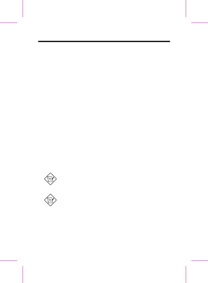
2.2.2 Selecting the CPU Frequency
JP3 |
JP1 |
JP2 |
CPU Frequency |
|
|
|
|
Ratio |
|
1-2 |
1-2 |
1-2 |
1.5x |
(3.5x) |
1-2 |
2-3 |
1-2 |
2x |
|
1-2 |
2-3 |
2-3 |
2.5x |
(1.75x) |
1-2 |
1-2 |
2-3 |
3x |
|
2-3 |
2-3 |
1-2 |
4x |
|
2-3 |
2-3 |
2-3 |
4.5x |
|
2-3 |
1-2 |
2-3 |
5x |
|
2-3 |
1-2 |
1-2 |
5.5x |
|
|
|
|
|
|
Intel Pentium, Cyrix 6x86 and AMD K5/K6 CPU are designed to have different Internal (Core) and External (Bus) frequency. The ratio of Core/Bus frequency is selected by JP1, JP2, which CPU is using to multiply external clock and produce internal frequency. Note that JP3 is reserved for future CPU.
Note: JP3 is reserved for future CPU. It is NC pin (no connection) for current CPU on the market. It should be no harm to connect to 1-2 or 2-3. If you find any unstable problem, please try to remove the jumper cap, and leave it Open.
Note: Intel PP/MT MMX 233MHz is using 1.5x jumper setting for 3.5x frequency ratio, and AMD PR166 is using 2.5x setting for 1.75x frequency ratio.
Core frequency = Ratio * External bus clock
2-6
Hardware Installation
JP3 |
JP1 |
JP2 |
JP3 |
JP1 |
JP2 |
1 2 3 |
1 2 3 |
1 2 3 |
1 2 3 |
1 2 3 |
1 2 3 |
1.5x (3.5x) |
|
2x |
|
||
JP3 |
JP1 |
JP2 |
JP3 |
JP1 |
JP2 |
1 2 3 |
1 2 3 |
1 2 3 |
1 2 3 |
1 2 3 |
1 2 3 |
2.5x (1.75x) |
|
3x |
|
||
JP3 |
JP1 |
JP2 |
JP3 |
JP1 |
JP2 |
1 2 3 |
1 2 3 |
1 2 3 |
1 2 3 |
1 2 3 |
1 2 3 |
|
4x |
|
|
4.5x |
|
JP3 |
JP1 |
JP2 |
JP3 |
JP1 |
JP2 |
1 2 3 |
1 2 3 |
1 2 3 |
1 2 3 |
1 2 3 |
1 2 3 |
|
5x |
|
|
5.5x |
|
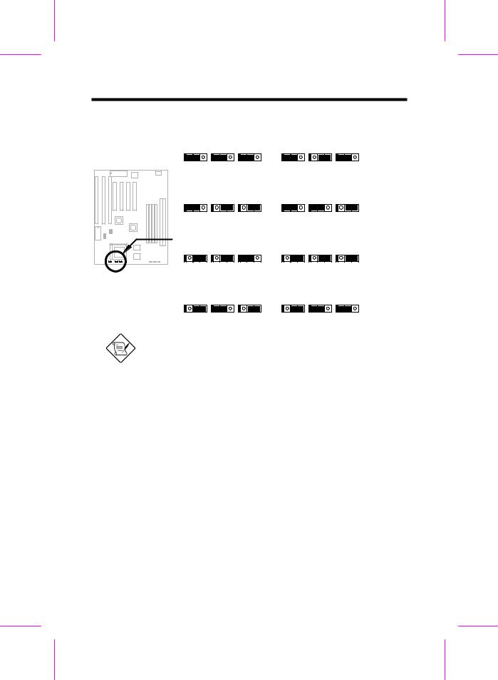
Note: Intel PP/MT 233MHz is using 1.5x jumper setting for 3.5x frequency ratio, and AMD PR166 is using 2.5x setting for 1.75x frequency ratio.
JP6 |
JP4 |
JP5 |
CPU External Clock |
JP6, JP4 and JP5 are the |
|||
1-2 |
1-2 |
2-3 |
60MHz |
selections |
of CPU |
external |
|
1-2 |
2-3 |
1-2 |
66MHz |
clock (bus |
clock), |
which is |
|
actually the |
clock from clock |
||||||
2-3 |
1-2 |
2-3 |
75MHz |
||||
generator. |
|
|
|||||
2-3 |
2-3 |
1-2 |
83.3MHz |
|
|
||
|
|
|
|||||
|
|
|
|
|
|
|
|
2-7
Hardware Installation
|
|
|
|
|
|
|
|
|
|
|
|
|
|
|
|
|
|
|
|
|
|
|
JP6 |
|
JP4 |
JP5 |
|
JP6 |
|
|
JP4 |
JP5 |
|||||||||||||||||
|
|
|
|
|
|
|
|
|
|
|
|
|
|
|
|
|
|
|
|
|
|
1 2 3 |
|
1 2 3 |
|
1 2 3 |
|
|
|
1 2 3 |
1 2 3 |
|
|
1 2 3 |
|
||||||||||||||
|
|
|
|
|
|
|
|
|
|
|
|
|
|
|
|
|
|
|
|
|
|
|
|
|
|
|
|
|
|
||||||||||||||||||||
|
|
|
|
|
|
|
|
|
|
|
|
|
|
|
|
|
|
|
|
|
|
|
|
|
|
|
|
|
|
|
|
|
|
|
|
|
|
|
|
|
|
|
|
|
|
|
|
|
|
|
|
|
|
|
|
|
|
|
|
|
|
|
|
|
|
|
|
|
|
|
|
|
|
|
|
|
60MHz |
|
|
|
|
|
|
|
|
|
|
66MHz |
|
|
|
||||||||
|
|
|
|
|
|
|
|
|
|
|
|
|
|
|
|
|
|
|
|
|
|
|
JP6 |
|
JP4 |
JP5 |
|
JP6 |
|
|
JP4 |
JP5 |
|||||||||||||||||
|
|
|
|
|
|
|
|
|
|
|
|
|
|
|
|
|
|
|
|
|
|
|
|
|
|
|
|||||||||||||||||||||||
|
|
|
|
|
|
|
|
|
|
|
|
|
|
|
|
|
|
|
|
|
|
||||||||||||||||||||||||||||
|
|
|
|
|
|
|
|
|
|
|
|
|
|
|
|
|
|
|
|
|
|
1 2 3 |
|
1 2 3 |
|
1 2 3 |
|
|
|
1 2 3 |
1 2 3 |
|
|
1 2 3 |
|
||||||||||||||
|
|
|
|
|
|
|
|
|
|
|
|
|
|
|
|
|
|
|
|
|
|
|
|
|
|
|
|
|
|
||||||||||||||||||||
|
|
|
|
|
|
|
|
|
|
|
|
|
|
|
|
|
|
|
|
|
|
||||||||||||||||||||||||||||
|
|
|
|
|
|
|
|
|
|
|
|
|
|
|
|
|
|
|
|
|
|
|
|
|
|
|
|
|
|
|
|
|
|
|
|
|
|
|
|
|
|
|
|
|
|
|
|
|
|
|
|
|
|
|
|
|
|
|
|
|
|
|
|
|
|
|
|
|
|
|
|
|
|
|
|
|
75MHz |
|
|
|
|
|
|
|
|
|
83.3MHz |
||||||||||||
|
|
|
|
|
|
|
|
|
|
|
|
|
|
|
|
|
|
|
|
|
|
|
|
|
|
|
|
|
|
|
|
|
|
|
|
||||||||||||||
|
|
|
|
|
|
|
|
|
|
|
|
|
|
|
|
|
|
|
|
|
|
|
|
|
|
|
|
|
|
|
|
|
|
|
|
||||||||||||||
|
|
|
|
|
|
|
|
|
|
|
|
|
|
|
|
|
|
|
Warning: INTEL TX chipset supports only 60/66MHz |
||||||||||||||||||||||||||||||
|
|
|
|
|
|
|
|
|
|
|
|
|
|
|
|
|
|
|
external CPU bus clock, the 75/83.3MHz settings are for |
||||||||||||||||||||||||||||||
|
|
|
|
|
|
|
|
|
|
|
|
|
|
|
|
|
|
|
internal test only, set to 75/83.3MHz exceeds the |
||||||||||||||||||||||||||||||
|
|
|
|
|
|
|
|
|
|
|
|
|
|
|
|
|
|
|
specification of TX chipset, which may cause serious |
||||||||||||||||||||||||||||||
|
|
|
|
|
|
|
|
|
|
|
|
|
|
|
|
|
|
|
system damage. |
|
|
|
|
|
|
|
|
|
|
|
|
|
|
|
|
|
|
|
|||||||||||
|
|
|
|
|
|
|
|
|
|
|
|
|
|
|
|
|
|
|
Caution: Following table are possible settings of current |
||||||||||||||||||||||||||||||
|
|
|
|
|
|
|
|
|
|
|
|
|
|
|
|
|
|
|
CPU available on the market. The correct setting may |
||||||||||||||||||||||||||||||
|
|
|
|
|
|
|
|
|
|
|
|
|
|
|
|
|
|
|
vary because of new CPU product, refer to your CPU |
||||||||||||||||||||||||||||||
|
|
|
|
|
|
|
|
|
|
|
|
|
|
|
|
|
|
|
specification for more details. |
|
|
|
|
|
|
|
|
|
|
|
|
|
|
||||||||||||||||
|
|
|
|
|
|
|
|
|
|
|
|
|
|
|
|
|
|
|
Warning: Cyrix 6x86 P200+ uses 75MHz external clock, |
||||||||||||||||||||||||||||||
|
|
|
|
|
|
|
|
|
|
|
|
|
|
|
|
|
|
|
the jumper setting shown on the table below is for user's |
||||||||||||||||||||||||||||||
|
|
|
|
|
|
|
|
|
|
|
|
|
|
|
|
|
|
|
convenient. It may cause serious system damage to use |
||||||||||||||||||||||||||||||
|
|
|
|
|
|
|
|
|
|
|
|
|
|
|
|
|
|
|
75MHz clock. |
|
|
|
|
|
|
|
|
|
|
|
|
|
|
|
|
|
|
|
|
|
|
|
|||||||
|
|
|
|
|
|
|
|
|
|
|
|||||||||||||||||||||||||||||||||||||||
INTEL |
|
|
|
CPU Core |
Ratio |
|
External |
|
JP3 & JP1 & JP2 |
JP6 & JP4 & JP5 |
|||||||||||||||||||||||||||||||||||||||
Pentium |
|
|
|
Frequency |
|
|
|
|
|
|
Bus Clock |
|
|
|
|
|
|
|
|
|
|
|
|
|
|
|
|||||||||||||||||||||||
P54C 90 |
|
|
|
90MHz = |
1.5x |
|
60MHz |
|
1-2 & 1-2 & 1-2 |
|
1-2 & 1-2 & 2-3 |
||||||||||||||||||||||||||||||||||||||
|
|
|
|
|
|
|
|
|
|
|
|
||||||||||||||||||||||||||||||||||||||
P54C 100 |
|
|
|
100MHz = |
1.5x |
|
66MHz |
|
1-2 & 1-2 & 1-2 |
|
1-2 & 2-3 & 1-2 |
||||||||||||||||||||||||||||||||||||||
|
|
|
|
|
|
|
|
|
|
|
|
||||||||||||||||||||||||||||||||||||||
P54C 120 |
|
|
|
120MHz = |
2x |
|
60MHz |
|
1-2 & 2-3 & 1-2 |
|
1-2 & 1-2 & 2-3 |
||||||||||||||||||||||||||||||||||||||
|
|
|
|
|
|
|
|
|
|
|
|
||||||||||||||||||||||||||||||||||||||
P54C 133 |
|
|
|
133MHz = |
2x |
|
66MHz |
|
1-2 & 2-3 & 1-2 |
|
1-2 & 2-3 & 1-2 |
||||||||||||||||||||||||||||||||||||||
P54C 150 |
|
|
|
150MHz = |
2.5x |
|
60MHz |
|
1-2 & 2-3 & 2-3 |
|
1-2 & 1-2 & 2-3 |
||||||||||||||||||||||||||||||||||||||
P54C 166 |
|
|
|
166MHz = |
2.5x |
|
66MHz |
|
1-2 & 2-3 & 2-3 |
|
1-2 & 2-3 & 1-2 |
||||||||||||||||||||||||||||||||||||||
P54C 200 |
|
|
|
200MHz = |
3x |
|
66MHz |
|
1-2 & 1-2 & 2-3 |
|
1-2 & 2-3 & 1-2 |
||||||||||||||||||||||||||||||||||||||
|
|
|
|
|
|
|
|
|
|
|
|
|
|
|
|
|
|
|
|
|
|
|
|
|
|
|
|
|
|
|
|
|
|
|
|
|
|
|
|
|
|
|
|
|
|
|
|
|
|
2-8

Hardware Installation
INTEL |
CPU Core |
Ratio |
External |
JP3 & JP1 & JP2 |
JP6 & JP4 & JP5 |
Pentium |
Frequency |
|
Bus Clock |
|
|
|
|
|
|
|
|
PP/MT 150 |
150MHz = |
2.5x |
60MHz |
1-2 & 2-3 & 2-3 |
1-2 & 1-2 & 2-3 |
|
|
|
|
|
|
PP/MT 166 |
166MHz = |
2.5x |
66MHz |
1-2 & 2-3 & 2-3 |
1-2 & 2-3 & 1-2 |
|
|
|
|
|
|
PP/MT 200 |
200MHz = |
3x |
66MHz |
1-2 & 1-2 & 2-3 |
1-2 & 2-3 & 1-2 |
PP/MT 233 |
233MHz = |
3.5x |
66MHz |
1-2 & 1-2 & 1-2 |
1-2 & 2-3 & 1-2 |
Cyrix 6x86 |
CPU Core |
Ratio |
External |
JP3 & JP1 & JP2 |
JP6 & JP4 & JP5 |
& 6x86L |
Frequency |
|
Bus Clock |
|
|
|
|
|
|
|
|
P150+ |
120MHz = |
2x |
60MHz |
1-2 & 2-3 & 1-2 |
1-2 & 1-2 & 2-3 |
|
|
|
|
|
|
P166+ |
133MHz = |
2x |
66MHz |
1-2 & 2-3 & 1-2 |
1-2 & 2-3 & 1-2 |
|
|
|
|
|
|
P200+ |
150MHz = |
2x |
75MHz |
1-2 & 2-3 & 1-2 |
2-3 & 1-2 & 2-3 |
Cyrix M2 |
CPU Core |
Ratio |
External |
JP3 & JP1 & JP2 |
JP6 & JP4 & JP5 |
|
Frequency |
|
Bus Clock |
|
|
MX-PR166 |
150MHz = |
2.5x |
60MHz |
1-2 & 2-3 & 2-3 |
1-2 & 1-2 & 2-3 |
|
|
|
|
|
|
MX-PR200 |
166MHz = |
2.5x |
66MHz |
1-2 & 2-3 & 2-3 |
1-2 & 2-3 & 1-2 |
|
|
|
|
|
|
MX-PR233 |
200MHz = |
3x |
66MHz |
1-2 & 1-2 & 2-3 |
1-2 & 2-3 & 1-2 |
|
|
|
|
|
|
MX-PR266 |
233MHz = |
3.5x |
66MHz |
1-2 & 1-2 & 1-2 |
1-2 & 2-3 & 1-2 |
|
|
|
|
|
|
AMD K5 |
CPU Core |
Ratio |
External |
JP3 & JP1 & JP2 |
JP6 & JP4 & JP5 |
|
Frequency |
|
Bus Clock |
|
|
PR90 |
90MHz = |
1.5x |
60MHz |
1-2 & 1-2 & 1-2 |
1-2 & 1-2 & 2-3 |
|
|
|
|
|
|
PR100 |
100MHz = |
1.5x |
66MHz |
1-2 & 1-2 & 1-2 |
1-2 & 2-3 & 1-2 |
|
|
|
|
|
|
PR120 |
90MHz = |
1.5x |
60MHz |
1-2 & 1-2 & 1-2 |
1-2 & 1-2 & 2-3 |
|
|
|
|
|
|
PR133 |
100MHz = |
1.5x |
66MHz |
1-2 & 1-2 & 1-2 |
1-2 & 2-3 & 1-2 |
|
|
|
|
|
|
PR166 |
116MHz = |
1.75x |
66MHz |
1-2 & 2-3 & 2-3 |
1-2 & 2-3 & 1-2 |
AMD K6 |
CPU Core |
Ratio |
External |
JP3 & JP1 & JP2 |
JP6 & JP4 & JP5 |
|
Frequency |
|
Bus Clock |
|
|
|
|
|
|
|
|
PR2-166 |
166MHz = |
2.5x |
66MHz |
1-2 & 2-3 & 2-3 |
1-2 & 2-3 & 1-2 |
|
|
|
|
|
|
PR2-200 |
200MHz = |
3x |
66MHz |
1-2 & 1-2 & 2-3 |
1-2 & 2-3 & 1-2 |
|
|
|
|
|
|
PR2-233 |
233MHz = |
3.5x |
66MHz |
1-2 & 1-2 & 1-2 |
1-2 & 2-3 & 1-2 |
IDT C6 |
CPU Core |
Ratio |
External |
JP3 & JP1 & JP2 |
JP6 & JP4 & JP5 |
|
Frequency |
|
Bus Clock |
|
|
|
|
|
|
|
|
C6-150 |
150MHz = |
2x |
75MHz |
1-2 & 2-3 & 1-2 |
2-3 & 1-2 & 2-3 |
|
|
|
|
|
|
C6-180 |
180MHz = |
3x |
60MHz |
1-2 & 1-2 & 2-3 |
1-2 & 1-2 & 2-3 |
C6-200 |
200MHz = |
3x |
66MHz |
1-2 & 1-2 & 2-3 |
1-2 & 2-3 & 1-2 |
2-9
 Loading...