


Dura-Power Electric Models
DSE-5 THRU DSE-120 COMMERCIAL WATER HEATERS
• Installation • Operation • Maintenance • Checklist • Limited Warranty
 CAUTION
TEXT PRINTED OR OUTLINED IN RED CONTAINS
INFORMATION RELATIVE TO YOUR SAFETY. PLEASE READ
THOROUGHLY BEFORE INSTALLING AND USING THIS
APPLIANCE. A DIVISION OF A.O.SMITH CORPORATION RENTON, WASHINGTON
www.hotwater.com
|
KEEP THIS MANUAL WITH THE HEATER FOR FUTURE REFERENCE. |
|
WHENEVER MAINTENANCE ADJUSTMENTS OR SERVICE IS REQUIRED. |
PRINTED IN U.S.A. 700 |
PART NO. 60047-004 REV.6 |
SUPERSEDES PART NO. 60047-004 REV.5 |
1
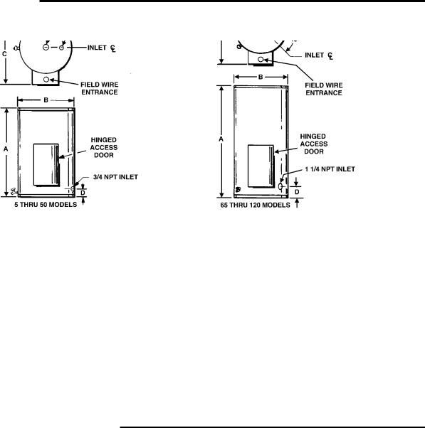
DIMENSIONS
Tank Capacity |
Maximum |
|
All Dimensions in Inches |
|
Approx. Ship |
||
in Gallons |
KW Input |
A |
B |
C |
|
D |
Wt.Lbs. |
5 |
3 |
20 /12 |
16 1/4 |
21 1/2 |
|
5 1/4 |
82 |
10 |
6 |
26 1/4 |
18 3/4 |
24 |
|
5 1/4 |
106 |
20 |
18 |
27 1/4 |
20 1/2 |
27 |
|
5 3/4 |
130 |
30 |
24 |
35 3/4 |
20 1/2 |
27 |
|
5 3/4 |
150 |
40 |
36 |
45 3/4 |
20 1/2 |
27 |
|
5 3/4 |
190 |
50 |
90 |
54 3/4 |
20 1/2 |
27 |
|
5 3/4 |
221 |
65 |
90 |
50 1/2 |
24 1/2 |
30 1/4 |
|
7 |
267 |
80 |
90 |
49 1/4 |
26 1/2 |
32 1/4 |
|
7 |
285 |
100 |
90 |
58 1/4 |
26 1/2 |
32 1/4 |
|
7 |
354 |
119 |
90 |
63 1/4 |
28 |
33 3/4 |
|
7 1/2 |
420 |
RECOVERY CAPACITY
RECOVERY RATE IN GALLONS PER HOUR *
Temperature Rise °F
STANDARD |
BTU/ |
30° |
40° |
50° |
60° |
70° |
80° |
90° |
100° |
110° |
120° |
130° |
140° |
KW INPUT |
HOUR |
|
|
|
|
|
|
|
|
|
|
|
|
|
|
|
|
|
|
|
|
|
|
|
|
|
|
3 |
10,239 |
41 |
31 |
24 |
20 |
17 |
15 |
13 |
12 |
11 |
10 |
10 |
9 |
|
|
|
|
|
|
|
|
|
|
|
|
|
|
6 |
20,478 |
82 |
62 |
49 |
41 |
35 |
31 |
27 |
25 |
22 |
21 |
19 |
18 |
|
|
|
|
|
|
|
|
|
|
|
|
|
|
9 |
30,717 |
123 |
92 |
74 |
62 |
53 |
46 |
41 |
37 |
34 |
31 |
28 |
26 |
|
|
|
|
|
|
|
|
|
|
|
|
|
|
12 |
40,956 |
164 |
123 |
98 |
82 |
70 |
61 |
55 |
49 |
45 |
41 |
38 |
35 |
|
|
|
|
|
|
|
|
|
|
|
|
|
|
15 |
51,195 |
205 |
154 |
123 |
102 |
88 |
77 |
68 |
61 |
56 |
51 |
47 |
44 |
|
|
|
|
|
|
|
|
|
|
|
|
|
|
18 |
61,434 |
246 |
184 |
148 |
123 |
105 |
92 |
82 |
74 |
67 |
62 |
57 |
53 |
|
|
|
|
|
|
|
|
|
|
|
|
|
|
24 |
81,912 |
328 |
246 |
197 |
164 |
140 |
123 |
109 |
98 |
90 |
82 |
76 |
70 |
|
|
|
|
|
|
|
|
|
|
|
|
|
|
30 |
102,390 |
410 |
308 |
246 |
205 |
176 |
154 |
137 |
123 |
112 |
103 |
95 |
88 |
|
|
|
|
|
|
|
|
|
|
|
|
|
|
36 |
122,868 |
492 |
369 |
295 |
246 |
211 |
184 |
164 |
148 |
134 |
123 |
113 |
105 |
|
|
|
|
|
|
|
|
|
|
|
|
|
|
45 |
153,585 |
615 |
461 |
369 |
307 |
263 |
230 |
205 |
184 |
168 |
154 |
142 |
132 |
|
|
|
|
|
|
|
|
|
|
|
|
|
|
54 |
184,302 |
738 |
554 |
443 |
359 |
316 |
277 |
246 |
221 |
201 |
185 |
170 |
158 |
60** |
204,780 |
819 |
615 |
492 |
410 |
351 |
307 |
273 |
246 |
223 |
205 |
189 |
176 |
75** |
255,975 |
1025 |
768 |
615 |
512 |
439 |
384 |
341 |
307 |
279 |
256 |
236 |
219 |
90** |
307,170 |
1229 |
922 |
738 |
615 |
527 |
461 |
410 |
369 |
335 |
307 |
284 |
263 |
*Figured at 1KW (3413 Btu) = 4.1 Gallons at 100°F temperature rise.
To determine recovery rate per minute, divide recovery rate per hour by 60.
NSF ratings may be obtained by multiplying above figures by 0.98.
**Available on 50 gallon models or larger.
2
FOREWORD
Detailed installation diagrams are in this manual. These diagrams will serve to provide the installer with a reference for the materials and method of piping suggested. IT IS NECESSARY THAT ALL WATER PIPING AND THE ELECTRICAL WIRING BE INSTALLED AND CONNECTED AS SHOWN IN THE DIAGRAMS.
Particular attention should be given to the installation of thermometers at the locations indicated in the diagrams as these are necessary for checking the operation of the heater.
In addition to these instructions, the equipment shall be installed in accordance with those installation regulations in force in the local area where installation is to be made. Authorities having jurisdiction shall be consulted before installations are made. BE SURE TO TURN OFF POWER WHEN WORKING ON OR
NEAR THE ELECTRICAL SYSTEM OF THE HEATER. NEVER TOUCH ELECTRICAL COMPONENTS WITH WET HANDS OR WHEN STANDING IN WATER. WHEN REPLACING FUSES ALWAYS USE THE CORRECT SIZE FOR THE CIRCUIT. SEE PAGE 14.
DO NOT TEST ELECTRICAL SYSTEM BEFORE HEATER IS FILLED WITH WATER, FOLLOW START UP PROCEDURE ON PAGE 17.
The principal components of the heater are identified on page 4. The model and rating plate on page 3 interprets certain markings into useful information. Both of these references should be used to identify the heater, its components and optional equipment.
CONTENTS
|
PAGE |
|
PAGE |
ROUGH-IN-DIMENSIONS ...................................... |
2 |
Amperage Table/Overcurrent Protection ........ |
14 |
RECOVERY CAPACITY ....................................... |
2 |
Heater Circuits ................................................ |
14 |
FOREWORD ......................................................... |
3 |
Control Circuit ................................................. |
14 |
APPROVALS ....................................................... |
3 |
Power Circuit .................................................. |
14 |
MODEL & RATING PLATE .................................... |
3 |
Wiring Diagram ................................................ |
15-17 |
GETTING TO KNOW YOUR WATER HEATER ...... |
4 |
OPERATION |
|
GENERAL SAFETY INFORMATION |
|
General ............................................................ |
17 |
Insulation Blankets .............................................. |
5 |
Filling ................................................................ |
17 |
External Damage ................................................. |
5 |
Start Up ........................................................... |
17 |
INSTALLATION |
|
Temperature Regulation .................................. |
17-18 |
Required Ability ................................................... |
5 |
Draining ........................................................... |
18 |
General ................................................................ |
5 |
MAINTENANCE |
|
Location ............................................................... |
5 |
General ............................................................ |
18 |
Connections ........................................................ |
6 |
Flushing ........................................................... |
18 |
Relief Devices ..................................................... |
6 |
Sediment Removal ........................................... |
18 |
Temperature Limiting Control ............................... |
6 |
Lime Scale Removal ........................................ |
18-19 |
Hydrogen Gas .................................................... |
6 |
Checklist .......................................................... |
19-20 |
PIPING DIAGRAMS .............................................. |
7-12 |
Replacement Parts .......................................... |
20 |
ELECTRICAL |
|
LEAKAGE CHECKPOINTS ............................... |
21 |
General ................................................................ |
13 |
LIMITED WARRANTY ...................................... |
22 |
Branch Circuit ...................................................... |
13 |
|
|
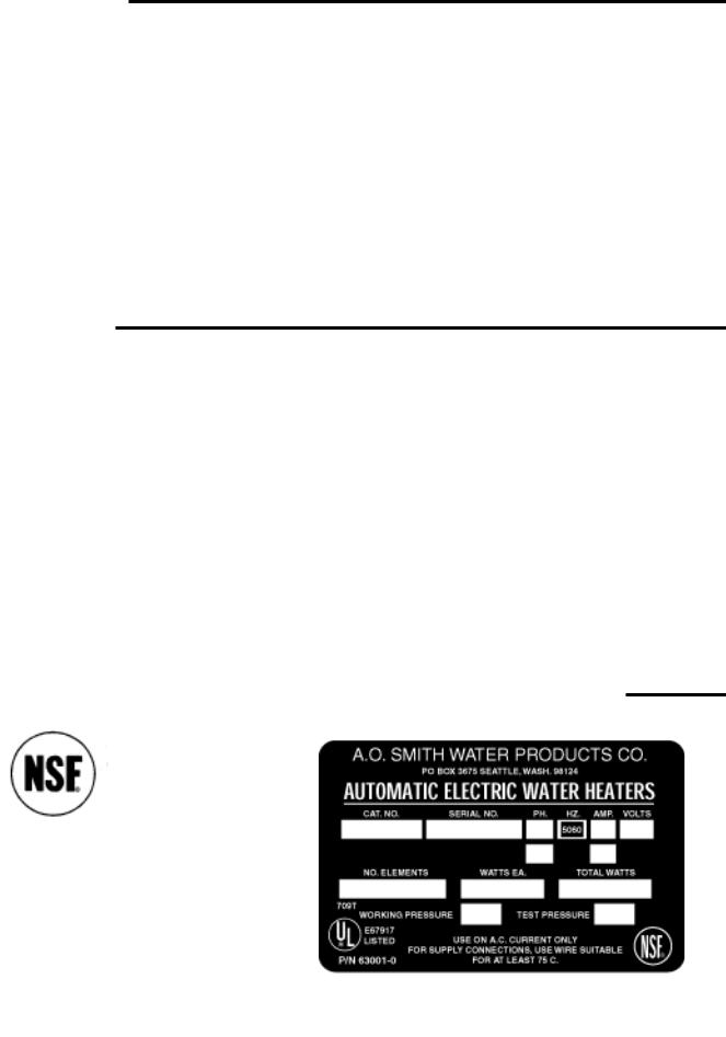
APPROVALS |
|
MODEL & RATING PLATE |
|
All models bear the National Sanitation Foundation seal of approval.
All models are listed
by Underwriters’ Laboratories, Inc.
125 PSI Working Pressure ASME (65 thru 120 Gallons)
150 PSI Working Pressure (5 thru 50 Gallons)
3

GETTING TO KNOW YOUR WATER HEATER
Below is an illustration of the water heater with its features called out. The text of this manual will refer to the items shown.
FIGURE 1
4

GENERAL SAFETY
INFORMATION
INSULATION BLANKETS
Insulation blankets available to the general public for external use on electric water heaters are not approved for use on your A.O. Smith water heater. The purpose of an insulation blanket is to reduce the standby heat loss encountered with storage tank water heaters. Your A.O. Smith water heater meets or exceeds the National Appliance Energy Conservation Act standards with respect to insulation and standby loss requirements, making an insulation blanket unnecessary.
 WARNING
Should you choose to apply an insulation blanket to this heater, you should follow these instructions (See Figure 1 for identification of components mentioned below). Failure to follow these instructions can result in fire, asphyxiation, serious personal injury or death.
1.DO NOT COVER THE JUNCTION BOX EXTERNAL WIRING, THERMOSTATS OR HEATING ELEMENTS ON ELECTRIC WATER HEATER.
2.DO NOT COVER THE TEMPERATURE-PRESSURE RELIEF VALVE.
3.DO NOT COVER OPERATING INSTRUCTIONS, INSTALLATION OR SAFETY RELATED LABELS.
.
4.DO OBTAIN NEW WARNING AND INSTRUCTION LABELS FROM A.O. SMITH FOR PLACEMENT ON THE BLANKET DIRECTLY OVER THE EXISTING LABELS.
5.WATER AND/OR CONDENSATE CAN COLLECT IN AN INSULATION BLANKET. A.O. SMITH WILL NOT BE LIABLE FOR ANY RUST OR CORROSION DAMAGE CAUSED BY THE INSTALLATION OF INSULATION BLANKETS.
 WARNING
FAILURE TO FOLLOW THESE INSTRUCTIONS CAN RESULT IN SERIOUS PERSONAL INJURY OR DEATH.
EXTERNAL DAMAGE
Do not operate the water heater until it has been fully checked out by a qualified service technician, if the water heater:
•Has been exposed to fire or damage.
•Produces steam or unusually hot water.
If the water heater has been subject to flooding, it must be replaced.
INSTALLATION
REQUIRED ABILITY
INSTALLATION OR SERVICE OF THIS WATER HEATER REQUIRES ABILITY EQUIVALENT TO THAT OF A LICENSED TRADESMAN IN THE FIELD INVOLVED. PLUMBING AND ELECTRICAL WORK INVOLVED.
GENERAL
The installation must conform to these instructions and the local code authority having jurisdiction. Grounding and electrical wiring connected to the water heater must also conform to the latest version of the NATIONAL ELECTRICAL CODE and NFPA70. Copies of these codes may be obtained from American National Standards Institute, 1430 Broadway, New York, NY 10018.
If your location requires the installation of the water heater to comply with National Sanitation Foundation requirements, the heater must be sealed to the floor so as to prevent seepage underneath the heater. The following are recommended sealants that may be used on all types of flooring except concrete: GE Silicone Seal RTV-120, 103, 108 and 109.
DO NOT TEST ELECTRICAL SYSTEM BEFORE HEATER IS FILLED WITH WATER, FOLLOW START UP PROCEDURE AS WRITTEN IN “OPERATION” SECTION OF THIS MANUAL.
The principal components of the heater are identified in figure 1. The model and rating plate on page 3 interprets certain markings into useful information. Both of these references should be used to identify the heater, its components and optional equipment.
LOCATION
For proper installation, the heater should be installed on a level surface.
LOCATE IT NEAR A FLOOR DRAIN. THE HEATER SHOULD BE LOCATED IN AN AREA WHERE LEAKAGE FROM THE HEATER OR CONNECTIONS WILL NOT RESULT IN DAMAGE TO THE ADJACENT AREA OR TO LOWER FLOORS OF THE STRUCTURE.
WHEN SUCH LOCATIONS CANNOT BE AVOIDED, A SUITABLE DRAIN PAN SHOULD BE INSTALLED UNDER THE HEATER. Such pans should be fabricated with sides at least 2” deep, with length and width at least 2” greater than the diameter of the heater and must be piped to an adequate drain. Drain pans suitable for these heaters are available from your distributor or A.O. Smith Water Products Company, Product Service Division, 5621 W. 115th St., Alsip, IL 60803.
Locate the heater close to the point of major hot water usage and the power supply.
•Try to make hot water piping and branch circuit wiring as short as possible.
•Insulate hot and cold water piping where heat loss and condensation may be a problem.
THE HEATER SHOULD NOT BE LOCATED IN AN AREA WHERE IT WILL BE SUBJECT TO FREEZING.
Suggested clearances from adjacent surfaces are 18 inches in front for access to the controls and elements and 12 inches from top. The heater may be installed on or against combustible surfaces.
CONNECTIONS
The heater water inlet is located on the side of the heater near the bottom. The heater outlet is located at the top of the heater.
Piping and wiring diagrams are included in this manual.
5
RELIEF DEVICES
An unplugged 3/4” relief valve opening is provided for installing temperature and pressure relief valve.
CAUTION: TO REDUCE THE RISK OF EXCESSIVE PRESSURES AND TEMPERATURE IN THIS WATER HEATER INSTALL TEMPERATURE AND PRESSURE PROTECTIVE EQUIPMENT REQUIRED BY LOCAL CODES but not less than a combination temperature and pressure relief valve certified by a nationally recognized testing laboratory that maintains periodic inspection of production of listed equipment or materials, as meeting the requirements for relief valve devices for hot water supply systems, ANSI Z21.22 (latest version).
This valve must be marked with a maximum set pressure not to exceed the marked maximum working pressure of the water heater. INSTALL THE VALVE INTO THE OPENING PROVIDED AND MARKED FOR THIS PURPOSE IN THE WATER HEATER, AND ORIENT IT OR PROVIDE TUBING SO THAT ANY DISCHARGE FROM THE VALVE WILL EXIT ONLY WITHIN 6 INCHES ABOVE, OR AT ANY DISTANCE BELOW THE STRUCTURAL FLOOR AND CANNOT CONTACT ANY LIVE ELECTRICAL PART. THIS DISCHARGE OPENING MUST NOT BE BLOCKED OR REDUCED IN SIZE UNDER ANY CIRCUMSTANCES.
The pressure setting of the relief valve should not exceed the pressure capacity of any component in the system. The temperature setting of the relief valve should not exceed 210°F.
TEMPERATURE LIMITING CONTROL
The heater control circuit contains a high temperature cutoff switch which operates if excessive water temperatures are reached. The high temperature cutoff contacts open at 190°F and must be manually reset (after a 30°F drop in water temperature). Disconnect the power before resetting button.
HYDROGEN GAS (FLAMMABLE)
 CAUTION
HYDROGEN GAS CAN BE PRODUCED IN A HOT WATER SYSTEM SERVED BY THIS HEATER THAT HAS NOT BEEN USED FOR A LONG PERIOD OF TIME (GENERALLY TWO WEEKS OR MORE). HYDROGEN GAS IS EXTREMELY FLAMMABLE. To reduce the risk of injury under these conditions, it is recommended that the hot water faucet be opened for several minutes at the kitchen sink before using any electrical appliance connected to the hot water system. If hydrogen is present, there will probably be an unusual sound such as air escaping through the pipe as the water begins to flow. THERE SHOULD BE NO SMOKING OR OPEN FLAME NEAR THE FAUCET AT THE TIME IT IS OPEN.
6
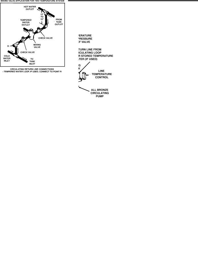
PIPING DIAGRAM
ONE OR TWO TEMPERATURE - ONE HEATER
CAUTION: IF BUILDING COLD WATER SUPPLY HAS A
BACK-FLOW PREVENTER, CHECK VALVE OR WATER
METER WITH CHECK VALVE, PROVISIONS FOR THERMAL
EXPANSION OF WATER IN THE HOT WATER SYSTEM MUST
BE PROVIDED.
*PIPE TO OPEN DRAIN.
INSTALL IN ACCORDANCE WITH ALL LOCAL CODES.
ONE OR TWO TEMPERATURE - TWO HEATER
 DANGER:
TEMPERATURE SETTING SHOULD NOT
EXCEED SAFE USE TEMPERATURE AT
FIXTURES. SEE WATER TEMPERATURE
CONTROL WARNING ON PAGES 17 & 18. IF
HIGHER PREHEAT TEMPERATURES ARE
NECESSARY TO OBTAIN ADEQUATE
BOOSTER OUTPUT, ADD AN ANTI-SCALD
VALVE FOR HOT WATER SUPPLIED TO
FIXTURES..
7
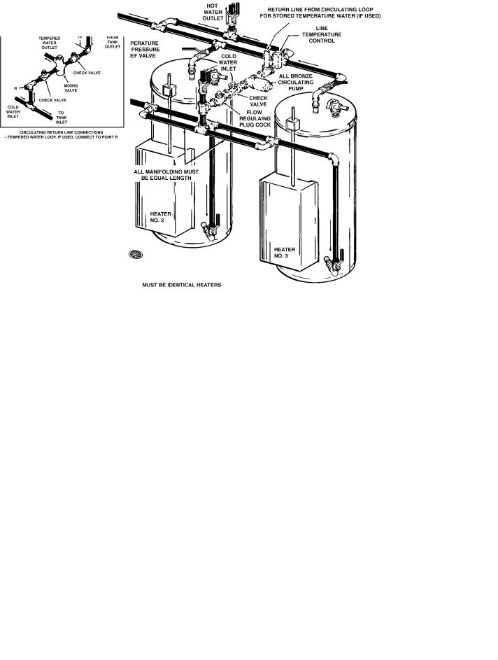
ONE OR TWO TEMPERATURE - THREE HEATERS
CAUTION: IF BUILDING COLD WATER SUPPLY HAS A
BACK-FLOW PREVENTER, CHECK VALVE OR WATER
METER WITH CHECK VALVE, PROVISIONS FOR THERMAL
EXPANSION OF WATER IN THE HOT WATER SYSTEM MUST
BE PROVIDED.
*PIPE TO OPEN DRAIN.
INSTALL IN ACCORDANCE WITH ALL LOCAL CODES.
ONE OR TWO TEMPERATURE - FOUR HEATERS
 DANGER:
TEMPERATURE SETTING SHOULD NOT EXCEED SAFE USE TEMPERATURE AT FIXTURES. SEE WATER TEMPERATURE CONTROL WARNING ON PAGES 17 & 18. IF HIGHER PREHEAT TEMPERATURES ARE NECESSARY TO OBTAIN ADEQUATE BOOSTER OUTPUT, ADD AN ANTI-SCALD VALVE FOR HOT WATER SUPPLIED TO FIXTURES..
8
 Loading...