


MODELS BTP-140-140 thru 600-2500
INCLUDING BTPD/BTPN/COF & COBT
COMMERCIAL GAS, OIL AND GAS/OIL TANK-TYPE WATER HEATERS
• INSTALLATION • OPERATION • SERVICE • MAINTENANCE • LIMITED WARRANTY
CONSERVATIONIST®
 ASME
ASME 
 CAUTION
TEXT PRINTED OR OUTLINED IN RED CONTAINS
INFORMATION RELATIVE TO YOUR SAFETY.
PLEASE READ THOUROUGHLY BEFORE USING
APPLIANCE.
A DIVISION OF A.O. SMITH CORPORATION
RENTON, WASHINGTON
www.hotwater.com
WARNING – PROPANE MODEL
Water heaters for propane gas are different from natural gas models. A natural gas heater will not function safely on propane gas and no attempt should be made to convert a heater from natural gas to propane gas.
Propane gas must be used with great caution. It is highly explosive and heavier than air. It collects first in the low areas making its odor difficult to detect. If propane gas is present or even suspected, do not attempt to find the cause yourself. Ventilate the room, then call your gas supplier or service agent. Keep area clear until a service agent has been called.
|
PLACE THESE INSTRUCTIONS ADJACENT TO HEATER AND |
|
|
|
NOTIFY OWNER TO KEEP FOR FUTURE REFERENCE |
PART NO. 60047-008 |
REV.6 |
|
|
||
PRINTED IN U.S.A. 3882 1100 |
1 |
SUPERSEDES 60047-008 |
REV.5 |

FOREWORD
This manual is intended to be used in conjunction with other literature provided with the heater. This includes power burner and related gas control information. It is important that this manual and the additional publications be reviewed in their entirety before beginning any work.
The installation should be made in accordance with the regulations of the local code authorities and utility companies, which pertain to this type of water heating equipment.
MAKE SURE the fuel on which the heater will operate is the same as that specified on the heater model and rating plate.
THESE HEATERS MUST NOT BE INSTALLED ON COMBUSTIBLE FLOORS.
Instructions for periodic testing of various water heater safety devices are included in section titled COMBUSTION
ARRANGEMENT REQUIREMENTS AND SERVICE RECOMMENDATIONS.
In the absence of local codes, the installation must comply with the instruction as outlined in the latest publication of ANSI booklet NFPA-54/ANSI Z223.1 “NATIONAL FUEL GAS CODE”, NFPA No. 70 “NATIONAL ELECTRICAL CODE”, or Canadian Gas Association booklet CAN 1-B149.1 or CAN 1-B149.2 for Canadian Installations also be followed.
These manuals can be purchased from the American Gas Association Laboratories, 8501 East Pleasant Valley Road, Cleveland, OH 44131 or the National Fire Protection Association, 1 Batterymarch Park, Quincy, MA 02269-9101, or Canadian Gas Association Labortories, 55 Scarsdale Road, Don Mills, Ontario, Canada M3B 2R3.
TABLE OF CONTENTS
|
PAGE |
|
PAGE |
FOREWORD ................................................................................ |
2 |
Gas Piping ............................................................................... |
7-8 |
IDENTIFICATION ......................................................................... |
2 |
Purging .................................................................................... |
8 |
GENERAL SAFETY INFORMATION ........................................... |
3 |
Gas Meter Size (City Gases Only) .......................................... |
8 |
Precautions ............................................................................. |
3 |
Gas Pressure Regulator .......................................................... |
8 |
Grounding Instructions ............................................................ |
3 |
Wiring ...................................................................................... |
8-11 |
Improper Combustion .............................................................. |
3 |
TWO UNIT MANIFOLD INSTALLATION ..................................... |
11 |
Liquid Petroleum Models ......................................................... |
3 |
OPERATION ................................................................................ |
11 |
Extended Non-Use Periods (BTP Models Only) ..................... |
3 |
Important ................................................................................. |
11 |
Insulation Blankets .................................................................. |
3 |
General .................................................................................... |
11 |
High Altitude Installations ........................................................ |
3-4 |
Filling ....................................................................................... |
11 |
FEATURES .................................................................................. |
4 |
Combustion Arrangement Requirements |
|
Water Temperature Control ..................................................... |
4 |
And Service Recommendations .............................................. |
11-12 |
INSTALLATION INSTRUCTIONS ................................................ |
4 |
MAINTENANCE ........................................................................... |
12 |
Required Ability ....................................................................... |
4 |
General .................................................................................... |
12 |
Uncrating ................................................................................. |
4-5 |
Flushing ................................................................................... |
12 |
Locating the Heater ................................................................. |
5 |
Draining ................................................................................... |
12 |
Leveling ................................................................................... |
5 |
Sediment Removal .................................................................. |
12 |
Clearances .............................................................................. |
5 |
Lime Scale Removal ............................................................... |
12-13 |
Air Requirements ..................................................................... |
5-6 |
Relief Valve ............................................................................. |
13 |
Thermal Expansion (Closed System) ...................................... |
6 |
Power Burner ........................................................................... |
13-14 |
Venting .................................................................................... |
6 |
Cleaning Flues - COF & COBT Only ....................................... |
14 |
Vent Connector ........................................................................ |
6 |
Vent Systems .......................................................................... |
14 |
Barometric Draft Control Assembly ......................................... |
6-7 |
Barometric Draft Control ......................................................... |
14 |
Water Line Connections .......................................................... |
7 |
TROUBLESHOOTING ................................................................. |
14-15 |
Thermometers (Not Supplied) ................................................. |
7 |
Replacement Parts .................................................................. |
15 |
Relief Valve ............................................................................. |
7 |
LIMITED WARRANTY ................................................................. |
16 |
This manual is supplemented by the power burner manual. All information, including start-up and maintenance relating to the burner, can be found in that manual.
IDENTIFICATION
The heater and burner mounted identification plates provide valuable information. When ordering parts or inquiring about a unit, be sure to include serial number, model number and type of fuel.
2
GENERAL SAFETY
INFORMATION
PRECAUTIONS
DO NOT USE THIS APPLIANCE IF ANY PART HAS BEEN UNDERWATER. Immediately call a qualified service technician to inspect the appliance and to replace any part of the control system and any gas control which has been under water.
IF THE UNIT IS EXPOSED TO THE FOLLOWING, DO NOT OPERATE HEATER UNTIL ALL CORRECTIVE STEPS HAVE BEEN MADE BY A QUALIFIED SERVICEMAN.
1.EXTERNAL FIRE.
2.DAMAGE.
3.FIRING WITHOUT WATER.
4SOOTING.
Heater must be protected from freezing downdrafts during shutdown periods.
GROUNDING INSTRUCTIONS
This water heater must be grounded in accordance with the National Electric Code and/or local codes. These must be followed in all cases.
This water heater must be connected to a grounded metal, permanent wiring system; or an equipment grounding conductor must be run with the circuit conductors and connected to the equipment grounding terminal or lead on the water heater.
CHEMICAL VAPOR CORROSION
 WARNING
CORROSION OF THE FLUEWAYS AND VENT SYSTEM MAY OCCUR IF AIR FOR COMBUSTION CONTAINS CERTAIN CHEMICAL VAPORS WHICH BREAK DOWN INTO ACIDS AT HIGH TEMPERATURE. SUCH CORROSION MAY RESULT IN FAILURE AND RISK OF ASPHYXIATION.
Spray can propellants, cleaning solvents, refrigerator and air conditioning refrigerants, swimming pool chemicals, calcium and sodium chloride (water softener salt), waxes, and process chemicals and typical compounds which are potentially corrosive. Do not store products of this sort near the heater. Also, air which is brought in contact with the heater should not contain any of these chemicals. If necessary, uncontaminated air should be obtained from remote or outside sources. The limited warranty is voided when failure of water heater is due to a corrosive atmosphere. (Refer to the limited warranty for complete terms and conditions).
IMPROPER COMBUSTION
 WARNING
ATTIC AND/OR EXHAUST FANS OPERATING ON THE PREMISES WITH A WATER HEATER CAN RESULT IN CARBON MONOXIDE POISONING AND DEATH.
OPERATING OF THESE FANS CAN PRODUCE A DOWN DRAFT IN THE AREA OF THE WATER HEATER PREVENTING THE PRODUCTS OF COMBUSTION FROM EXHAUSTING THROUGH THE CHIMNEY OR VENT PIPE.
The venting of the water heater should be inspected by a qualified service technician at the time of installation and periodically thereafter to ensure a down-draft condition does not exist.
DO NOT OBSTRUCT THE FLOW OF COMBUSTION AND VENTILATING AIR. ADEQUATE AIR FOR COMBUSTION AND VENTILATION MUST BE PROVIDED FOR SAFE OPERATION.
LIQUID PETROLEUM MODELS
Water heaters for propane or liquefied petroleum gas (LPG) are different from natural gas models. A natural gas heater will not function safely on LP gas and no attempt should be made to convert a heater from natural gas to LP gas.
LP gas must be used with great caution. It is highly explosive and heavier than air. It collects first in the low areas making its odor difficult to detect at nose level. If LP gas is present or even suspected, do not attempt to find the cause yourself. Ventilate the area, then call your gas supplier or service agent. Keep area clear until a service call has been made.
The presence of LP gas may be difficult to detect. The use of a propane gas detector is recommended.
Only trained LP professionals should conduct the required safety checks in accordance with industry standards.
EXTENDED NON-USE PERIODS
 WARNING
HYDROGEN GAS CAN BE PRODUCED IN A HOT WATER SYSTEM SERVED BY THIS HEATER THAT HAS NOT BEEN USED FOR A LONG PERIOD OF TIME (GENERALLY TWO WEEKS OR MORE). HYDROGEN GAS IS EXTREMELY FLAMMABLE. To reduce the risk of injury under these conditions, it is recommended that a hot water faucet be opened for several minutes before using any electrical appliance connected to the hot water system. If hydrogen is present, there will probably be an unusual sound such as air escaping through the pipe as the water begins to flow. THERE SHOULD BE NO SMOKING OR OPEN FLAME NEAR THE FAUCET AT THE TIME IT IS OPEN.
INSULATION BLANKETS
Insulation blankets available to the general public for external use on gas water heaters are not approved for use on your A.O. Smith water heater. The purpose of an insulation blanket is to reduce the standby heat loss encountered with storage tank water heaters. Your A.O. Smith water heater meets or exceeds the ASHRAE/IES 90.1b-1992 standards with respect to insulation and standby loss requirements making an insulation blanket unnecessary.
 WARNING
The application of an insulation blanket will void the warranty for this water heater. Furthermore, the application of an insulation blanket may interfere with the operation of this water heater, possibly resulting in property damage, injury, or death.
HIGH ALTITUDE INSTALLATIONS
Your A.O. Smith water heater has been designed to operate at altitudes above 2000 feet, provided that requirement was specified at the time of order. The firing rate will be specified on the water heater rating plate.
3
Note: Some gas utility companies derate the heating value of the supplied gas at high elevations. Your authorized A.O. Smith StartUp Agent must adjust for actual heating valve of the gas at the time of start-up.
FEATURES
WATER TEMPERATURE CONTROL
 WARNING
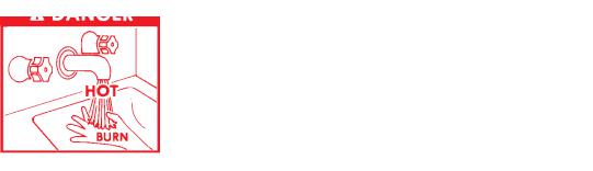
THIS WATER HEATER IS EQUIPPED WITH AN ADJUSTABLE THERMOSTAT TO CONTROL WATER TEMPERATURE. HOT WATER TEMPERATURES REQUIRED FOR AUTOMATIC DISHWASHER AND LAUNDRY USE CAN CAUSE SCALD BURNS RESULTING IN SERIOUS PERSONAL INJURY AND/ OR DEATH. THE TEMPERATURE AT WHICH INJURY OCCURS VARIES WITH THE PERSON’S AGE AND TIME OF EXPOSURE. THE SLOWER RESPONSE TIME OF DISABLED PERSONS INCREASES THE HAZARDS TO THEM. NEVERALLOW SMALL CHILDREN TO USE HOT WATER TAP, OR TO DRAW THEIR OWN BATH WATER. NEVER LEAVE A CHILD OR DISABLED PERSON UNATTENDED IN A BATHTUB OR SHOWER.
THE WATER HEATER SHOULD BE LOCATED IN AN AREA WHERE THE GENERAL PUBLIC DOES NOT HAVE ACCESS TO SET TEMPERATURES.
SETTING THE WATER HEATER TEMPERATUREAT 120°F WILL REDUCE THE RISK OF SCALDS. Some states or provinces require settings at specific lower temperatures.
Below you will find listed the appropriate time-to-burn relationship for normal adult skin. Short repeated heating cycles caused by small hot water uses can cause temperatures at the point of use to exceed the thermostat setting by up to 20°F (11°C). If you experience this type of use, you should consider using lower temperature settings to reduce scald hazards.
Temperature |
Time to Produce 2nd & 3rd |
Setting |
Degree Burns on Adult Skin |
180°F (82°C) |
Nearly Instantaneous |
170°F (77°C) |
Nearly Instantaneous |
160°F (71°C) |
About 1/2 Second |
150°F (65°C) |
About 1-1/2 Seconds |
140°F (60°C) |
Less than 5 Seconds |
130°F (54°C) |
About 30 Seconds |
120°F (49°C) |
More than 5 Minutes |
Valves for reducing point-of-use temperature by mixing cold and hot water are available. Also available are inexpensive devices that attach to faucets to limit hot water temperatures. Contact a licensed plumber or the local plumbing authority.
The water temperature is controlled by two thermostats. One thermostat is located near the top of the tank and the other is in the lower part of the tank. The upper thermostat must be set at least 5°F higher than the lower thermostat. In the case where the water heater has electronic thermostats, this differential has been factory set and cannot be changed.
The thermostat temperature dials are accessible by opening the control compartment cover.
FIGURE 1
A high limit switch interrupts the power burner operation should the water temperature reach 200°F.
The high limit switch must be manually reset by depressing the red button on the front of the control when water temperature drops to about 180°F. The manual reset high limit can be found inside the control compartment.
INSTALLATION INSTRUCTIONS
REQUIRED ABILITY
INSTALLATION OR SERVICE OF THIS WATER HEATER IS REQUIRED TO BE PERFORMED BY AN AUTHORIZED A.O. SMITH STARTUP AGENT. PLUMBING, AIR SUPPLY, VENTING, GAS SUPPLY AND ELECTRICAL WORK ARE REQUIRED.
UNCRATING
The heater should be moved in the crate as close as possible to the installation site. Depending upon size, shipping weights range from about 1,300 to 4,500 pounds.
The installer should be guided by the instructions furnished with the heater, local codes and utility company requirements. Preference should be given to codes and requirements where they differ from the heater furnished instructions.
Additional publications, which should guide the installer, include:
The latest version of the National Fuel Gas Code, ANSI Z223.1, from American Gas Association Laboratories, 8501 East Pleasant Valley Road, Cleveland, OH 44131.
In Canada – CGA No. B149 (latest version), from Canadian Gas Association Laboratories, 55 Scarsdale Road, Don Mills, Ontario, Canada M3B 2R3.
Code for the installation of Heat Producing Appliances (latest version), from American Insurance Association, 85 John Street, New York, NY 11038.
4

The latest version of the National Electrical Code, NFPA No. 70. In Canada refer to Canadian Electrical Code C 22.1, from National Fire Protection Association, 1 Batterymarch Park, Quicy, MA 02269-9101.
LOCATING THE HEATER
When installing the heater, consideration must be given to proper location. Location selected should be as close to the stack or chimney as practicable, with adequate air supply and as centralized with the piping system as possible.
 WARNING
THERE IS A RISK IN USING FUEL BURNING APPLIANCES SUCH AS GAS WATER HEATERS IN ROOMS, GARAGES OR OTHER AREAS WHERE GASOLINE, OTHER FLAMMABLE LIQUIDS OR ENGINE DRIVEN EQUIPMENT OR VEHICLES ARE STORED, OPERATED OR REPAIRED. FLAMMABLE VAPORS ARE HEAVY AND TRAVEL ALONG THE FLOOR AND MAY BE IGNITED BY THE HEATER’S IGNITION SYSTEM OR MAIN BURNER FLAMES CAUSING FIRE OR EXPLOSION.
SOME LOCAL CODES PERMIT OPERATION OF GAS APPLIANCES IF INSTALLED 18 INCHES OR MOREABOVE THE FLOOR. THIS MAY REDUCE THE RISK IF LOCATION IN SUCH AN AREA CANNOT BE AVOIDED.
THE HEATER SHALL BE LOCATED OR PROTECTED SO IT IS NOT SUBJECT TO PHYSICAL DAMAGE BY A MOVING VEHICLE.
 WARNING
FLAMMABLE ITEMS, PRESSURIZED CONTAINERS OR ANY OTHER POTENTIAL FIRE HAZARDOUS ARTICLES MUST NEVER BE PLACED ON OR ADJACENT TO THE HEATER. OPEN CONTAINERS OF FLAMMABLE MATERIAL SHOULD NOT BE STORED OR USED IN THE SAME ROOM WITH THE HEATER.
THE HEATER MUST NOT BE LOCATED IN AN AREA WHERE IT WILL BE SUBJECT TO FREEZING.
LOCATE HEATER NEAR A FLOOR DRAIN. THE HEATER SHOULD BE LOCATED IN AN AREA WHERE LEAKAGE FROM THE TANK OR CONNECTIONS WILL NOT RESULT IN DAMAGE TO THE ADJACENT AREA OR TO LOWER FLOORS OF THE STRUCTURE.
WHEN SUCH LOCATIONS CANNOT BE AVOIDED, A SUITABLE METAL DRAIN PAN, ADEQUATELY DRAINED, SHOULD BE INSTALLED UNDER THE HEATER. Such pans should be fabricated with sides at least 2” deep, with length and width at least 2” greater than the diameter of the heater and must be piped to an adequate drain. The pan must not restrict combustion air flow.
This unit must be installed on a non-combustible surface.
LEVELING
The heater shall be installed level. If it is necessary to adjust the heater, use metal shims under the channel-type skid base.
CLEARANCES
Provide ample clearance on all sides for installation, adjustment and replacement of burner, control components and other parts.
5
A clearance of 24” should be maintained from serviceable parts, such as relief valve, power burner, thermostat and drain valve.
MINIMUM INSTALLATION CLEARANCES
BTP/BTPN/BTPD |
COF/COBT |
FRONT - 18 Inches |
FRONT - 18 Inches |
BACK - 0 Inches |
Back - 6 Inches |
TOP - 5 Inches |
Top - 12 Inches |
LEFT SIDE - 0 Inches |
LEFT SIDE - 6 Inches |
RIGHT SIDE - 0 Inches |
RIGHT SIDE - 6 Inches |
NOTE: If a chimney connector is used, the minimum clearance from the top of the unit to the connector is 18 inches.
AIR REQUIREMENTS
 WARNING
FOR SAFE OPERATION, AN AMPLE SUPPLY OF AIR MUST BE PROVIDED FOR PROPER COMBUSTION AND VENTILATION AIR IN ACCORDANCE WITH SECTION 5.3, AIR FOR COMBUSTION AND VENTILATION, OF THE NATIONAL FUEL GAS CODE, NFPA-54/ANSI Z223.1 OR APPLICABLE PROVISIONS OF THE LOCAL BUILDING CODES. AN INSUFFICIENT SUPPLY OF AIR WILL RESULT IN A YELLOW, LUMINOUS BURNER FLAME, CAUSING CARBONING OR SOOTING OF THE HEAT EXCHANGER AND CREATING A RISK OF ASPHYXIATION. DO NOT OBSTRUCT THE FLOW OF COMBUSTION AND VENTILATION AIR.
UNCONFINED SPACE
In buildings of conventional frame, brick or stone construction, unconfined spaces may provide adequate air for combustion.
If the unconfined space is within a building of tight construction (buildings using the following construction: weather stripping, heavy insulation, caulking, vapor barrier, etc.), air for combustion, ventilation and draft hood dilution must be obtained from outdoors or spaces freely communicating with the outdoors. The installation instructions for confined spaces in tightly constructed buildings must be followed to ensure adequate air supply.
CONFINED SPACE
When drawing combustion and dilution air from inside a conventionally constructed building to a confined space, such a space shall be provided with two permanent openings, ONE IN OR WITHIN 12 INCHES OF THE ENCLOSURE TOP AND ONE IN OR WITHIN 12 INCHES OF THE ENCLOSURE BOTTOM. Each opening shall have a free area of at least one square inch per 1000 Btu/hr of the total input of all appliances in the enclosure, but not less than 100 square inches.
If the confined space is within a building of tight construction, air for combustion, ventilation and draft dilution must be obtained from outdoors. When directly venting with the outdoors or venting with the outdoors through vertical ducts, two permanent openings, located in the aforementioned manner, shall be provided. Each opening shall have a free area of not less than one square inch per 4000 Btu/hr of the total input of all appliances in the enclosure. If horizontal ducts are used, each opening shall have a free area of not less than one square inch per 2000 Btu/hr of the total input of all appliances in the enclosure.
Where an exhaust fan is installed in the same room with the boiler, sufficient openings for air must be provided in the walls. UNDERSIZED OPENINGS WILL CAUSE AIR TO BE DRAWN INTO THE ROOM THROUGH THE CHIMNEY OR OTHER
 Loading...