


BTI 85 G

MODELS
BTI 85 G
BTI 100 G
INSTALLATION AND USER
INSTRUCTION
UNITED KINGDOM / IRELAND
HOT WATER STORAGE HEATERS

Read these installation instructions first before installing the appliance. Carefully read
the user instructions before igniting the appliance. Failure to follow these instructions
may lead to risk of explosion and/or fire and could cause material damage and/or bodily
harm. Installation and commisioning should be carried out by a qualified competent
installer. The type of gas and the value at which the appliance is set standard in the
factory are registered on the rating plate. The appliance may only be installed in a room if
this room meets the ventilation requirements.
A.O. SMITH ACCEPTS NO RESPONSIBILITY FOR WARRANTY, SERVICE AND/OR
PRODUCT LIABILITY IN CASE OF UNAUTHORISED ALTERATIONS, PRODUCT
MODIFICATIONS OR REPAIR.
2

CONTENTS PAGE
1. GENERAL
1.1 Description...................................................................................................... 4
1.2 Technical safety equipment ............................................................................ 6
1.2.1 Gas control valve ............................................................................................ 6
1.2.2 Control panel................................................................................................... 6
1.2.3 Operation of the storage water heater ........................................................... 7
1.2.4 Combustion products discharge safety device ............................................. 7
1.3 Technical information ...................................................................................... 8
1.3.1 Dimensions ..................................................................................................... 8
1.3.2 Technical data ............................................................................................... 10
2. FOR THE INSTALLER
2.1 Installation instructions.................................................................................. 12
2.1.1 Installation ..................................................................................................... 12
2.1.2 Water circulation system .............................................................................. 13
2.1.3 Gas connection ............................................................................................. 15
2.1.4 Flue system .................................................................................................. 15
2.1.5 Flue down draught safety device ................................................................. 15
2.1.6 Electrical connection ..................................................................................... 15
2.2 Commissioning .............................................................................................. 16
2.2.1 Filling the water heater ................................................................................. 16
2.2.2 Putting in to operation.................................................................................... 16
2.2.3 Shut down .................................................................................................... 16
2.3 Removing and replacing the control panel front cover.................................. 17
2.4 Setting the gas pressure .............................................................................. 17
2.5 Removing and replacing the inner door......................................................... 18
2.6 Temperature regulation ................................................................................. 18
2.7 Converting to another type of gas ................................................................ 19
2.8 Maintenance ................................................................................................. 19
2.8.1 Magenesium anode ....................................................................................... 19
2.8.2 Cleaning ........................................................................................................ 20
2.8.3 Decalcification...............................................................................................20
2.8.4 Spare parts ................................................................................................... 20
2.9 Inlet combination............................................................................................ 20
2.10 Gas smell ...................................................................................................... 20
2.11 Condensation................................................................................................ 20
3. FOR THE USER
3.1 Commisioning ................................................................................................ 21
3.1.1 Filling the water heater ................................................................................. 21
3.1.2 Putting into operation..................................................................................... 21
3.1.3 Use ............................................................................................................... 21
3.2 Fault overview ..............................................................................................22
4. WARRANTY..................................................................................................... 23
5. Appendix 1..................................................................................................... 25
3

1. GENERAL
1.1 Description of the
appliance
Construction of the water heater is in
accordance with the European
standard for gas heated water storage
heaters for sanitary application (EN89).
The appliance thus meets the European
Directory for Gas Appliances and is
therefore entitled to carry the CEmarking. It is an open flued appliance
without ventilator and with a flue gas
down draught safeguard, a Thermal
Reflux Safeguard (TRS) (category
B
). The water heater is suitable for a
11BS
maximum working pressure of 8 bar.
The water heater tank is manufactured
from low carbon sheet steel and is
glasslined on the inside. In addition the
tank is fitted with a magenesium anode
as extra protection against corrosion. A
thick, CFC-free, PU insulation layer
covered in a steel jacket reduces
unnecessary heat loss. When the
appliance is filled with water it
continuously is under water pressure.
As hot water is drained from the tank,
cold water is added immediately. Four
flue baffles have been placed in the flue
tube to improve heat tranfer. The flue
gasses pass their heat on to the water
by means of radiation and convection.
The exhaust of the flue gasses is
realized by natural thermal draught (see
figur 1).
exceeding 25 mm. maximum length of
dead leg 3 metres.
Dead legs on a hot water installation are
undesireable. Where possible they
should be avoided. When the inclusion
on the system of a dead leg is
unavoidable the following restrictions
should be applied:
- for pipes not eceeding 19 mm. inside
diameter; maximum length of dead leg
permitted 12 metres;
- for pipes exceeding19 mm. but not
exceeding 25 mm. inside diameter;
maximum lenght of dead leg 7,5
metres;
- for pipes with an inside diameter
4
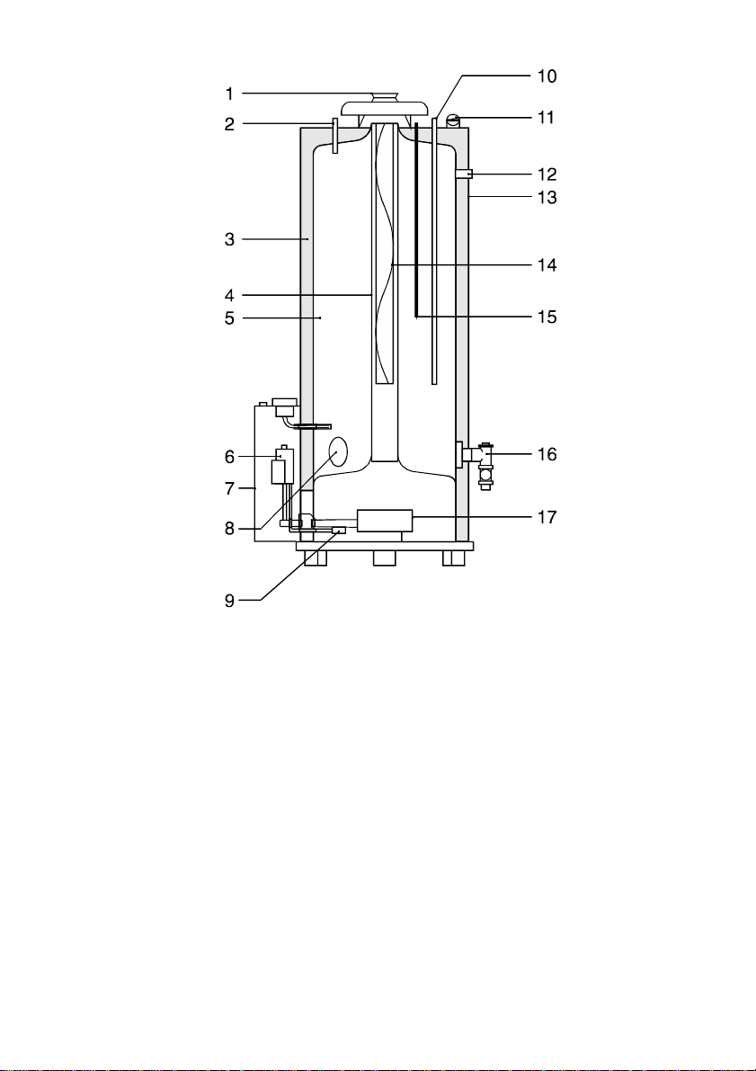
Figur 1 - Cross section of the heater
1) Draught diverter
2) Hot water outlet
3) Insulation
4) Flue tube
5) Glass lined tank
6) Gas valve and spark ignition
7) Control panel
8) Inspection cover plate
9) Intermittent pilot burner and
flame probe
10) Cold water inlet
11) Combustion products discharge
safety device
12) T&P valve connection
13) Outer casting
14) Flue baffle
15) Magnesium anode
16) Drain valve and secondary
return connection
17) Main burner
5
1.2 Technical safety
equipment
1.2.1 Gas control valve
The water heater is equipped with a
gas control wich regulates the flow of
gas to the burner. The gas block is
equipped with a safety valve, gas valve
and burner control (on a standard
natural gas setting). To ensure
improved ignition the gas control valve
opening mechanism is fitted with a
delay (softlite).
The gas control block is suitable for
gasses from the first, second and third
gas family. The maximum inlet pressure
is 60 mbar.
The automatic incandescent ignition (hot
surface) ensures that the burner ignites
as soon as there is a demand for heat.
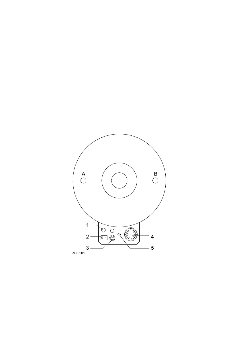
1.2.2 Control panel
Temperature control for the water
heater is housed in the control panel
(See figur 2). For safety purposes,
heaters are always fitted with two
thermostats: a control thermostat is
adjustable between 40 °C and 80 °C
and a safety thermostat 90 °C. The
control panel is fitted with an ON/OFF
switch (I/0). At setting ”I”, the gas
control is activated on the basis of heat
demand from the control thermostat. At
setting ”0” the heater is switched off.
Figur 2 - Top view of the heater
A) Hot water outlet
B) Cold water inlet
1) Electrical connection
2) ON/OFF switch
3) Ignition controller reset button
4) Control thermostat knob
5) Safety thermostat reset button
6

1.2.3 Operation of the storage
water heater.
Normal operation
When there is a demand for heat a
waiting period of about 1 second
elapses before the built-in spark generator and pilot gas valve are switched
on. The ignition sparks ignite the pilot
burner and the resulting flame is
detected by the ionisation electrode.
Almost immediately after the pilot flame
is detected, sparking stops and the
main gas valve is openend. The main
burner is lit by the pilot flame. The unit
is now in operation. When the
temperature of the water in the unit
reaches the temperature that is set
with the thermostat, the thermostat
switches and disconnects the
electrical heat demand signal to the
burner controller. The gas valves are
then closed.
Ignition failure
If the flame is not established within
the safety period the automatic ignition
controller locks out. The safety period
is about 25 seconds. Lock-out is
indicated by the lamp in the RESETbutton on the control panel. The unit
has to be manually reset by pushing
the reset button. If the flame is lost
during normal run, the automatic
ignition controller repeats the start
sequence.
operation by pressing its reset button. If
this failure occurs frequently, this
indicates that the flue suffers from down
draught conditions. It is recommended
that a competent person carry out the
necessary remedial action.
Important
The combustion products
discharge safety device should
never be put out of operation. Reentry of flue gases to the building
could be harmful and cause
poisoning or death.
1.2.4 Combustion products
discharge safety device
The heater has been fitted with a
combustion products discharge safety
device. It is the function of the safety
device to prevent flue gases from the
water heater entering the room where
the water heater has been placed,
instead of passing through the flue to
outside atmosphere. The gas supply is
disconnected as soon as the device is
activated by hot gases flowing over
the sensor. After the cause of the reentry of flue gases has been traced
the device can be put back into
7

1.3 Technical information
1.3.1 Dimensions
These water heaters are only suitable
for a flue tube with minimal the
announced diameter (dimension G).
Dimensions BTI 85 BTI 100
A 1585 1780
B 1450 1640
D 645 675
F 770 775
G 130 130
K 340 340
L 355 370
M 1505 1685
N 1505 1685
P 210 210
R 285 285
S 1280 1460
V 410 410
1 Cold water inlet
2 Hot water outlet
3 Gas control
4 Drain valve
5 T&P relief valve tapping
6 Clean out
All dimensions are given in mm. (rounded off on 5mm). See figur 3.
8
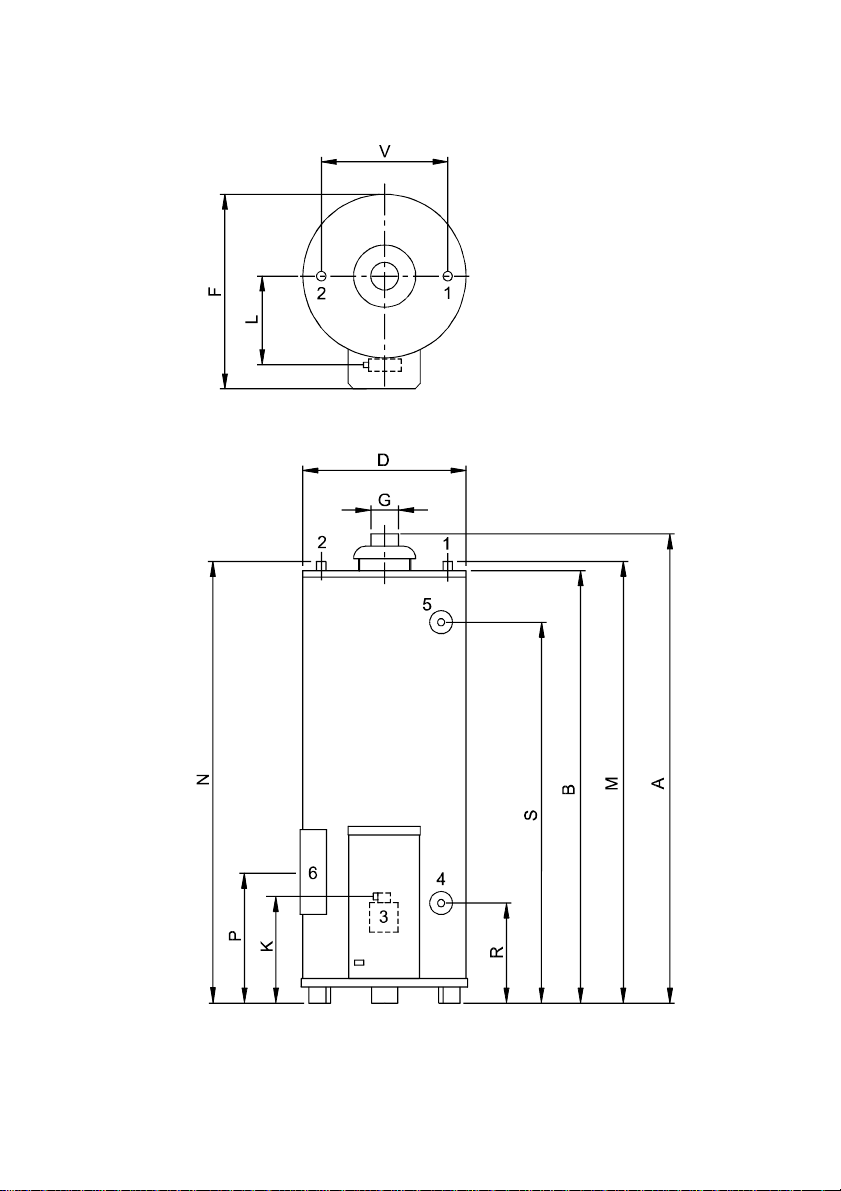
Figur 3 - Dimensions
AOS 1092
9
 Loading...