


New Solution Series
NSK 1480
User’s Manual
Manuel de l’utilisateur
Anwenderhandbuch
Manuale per l’operatore
Manual del usuario

At Antec, we continually refine and improve our products to ensure the highest quality. As such, your new case may differ slightly from the description in this manual. This isn’t a problem; it’s simply an improvement. As of the date of publication, all features, descriptions, and illustrations in this manual are correct.
Disclaimer
This manual is intended only as a guide for Antec’s Computer Enclosures. For more comprehensive instructions on installing the motherboard and peripherals, please refer to the user’s manuals that come with those components.
New Solution Series User’s Manual
NSK 1480
Quiet Desktop Slim Case The Power Supply
The NSK 1480 comes with a 350-Watt power supply (PSU) that features universal input and active PFC. This includes dual 12V output rails that deliver safer and more reliable output to the system’s components. This PSU has achieved 80 PLUS® Certification, the latest independent standard in power supply efficiency. It reduces power consumption by up to 25%, saving you money on your electricity bill. In addition it has a variety of industrial-grade protective circuitry: OPP (over power protection), OVP (over voltage protection), UVP (under voltage protection), and SCP (short circuit protection).
The Rubber Pads/Stands
There are four rubber pads inside the tool bag. If you want to place the case horizontally on a desktop, stick the rubber pads to the bottom of the case. There are also two stands so the case can stand up vertically. Place the case onto the stands with the optical drive bay at its top position. Make sure the stands do not block the two air intakes on the bottom.
Setting Up
1.Place the case upright on a flat, stable surface.
2.Remove the thumbscrews from the back of the top panel. Slide the panel towards the rear to remove it from the case.
3.Inside the case you should see the power supply, some wiring with marked connectors (USB, PWR etc.), and installed I/O panel and a power cord.
The Dual Chamber structure
Upon opening the top panel, you will find that the case is divided into two separate chambers—the motherboard chamber and the HDD chamber. The power supply is designed to directly suck fresh air from outside the case. This unique feature combined with the dual chamber structure isolates heat and noise from each section, resulting in much quieter and cooler operation than a traditional desktop case. Although care has been taken to prevent sharp edges in your Antec case, we strongly recommend taking the appropriate time and care when working with it. Avoid excessive force and hurried or careless motions. Please take reasonable precautions.
1
Installing the Motherboard
This manual is not designed to cover CPU, RAM, or expansion card installation. Please consult the motherboard manual for specific mounting instructions and troubleshooting.
The motherboard is located inside the main chamber with two 80 mm TriCool TM fans preinstalled right next to the CPU.
1.Lay the case down, with the open side facing up. The drive cages and power supply should be visible.
2.Make sure you have the appropriate I/O panel for the motherboard. If the panel provided is not suitable for the motherboard, please contact the motherboard manufacturer for the correct I/O panel.
3.Remove the cross bar on the motherboard chamber.
4.Line up the motherboard with the mounting holes. There are three special brass standoffs pre-installed on the motherboard tray. Two of them are threaded and one is an unthreaded post. Make note of any that don’t line up with a corresponding hole in the motherboard. Not all motherboards will match with all of the provided screw holes, and this is not necessary for proper functionality.
5.Remove the motherboard by lifting it up.
6.Remove any of the pre-installed standoffs that aren’t needed.
7.Place the motherboard back on the standoffs. Attach the motherboard to the threaded brass standoffs with the special nuts that comes with your tool bag. Note: You do not need to fasten the unthreaded brass standoff.
8.Fasten the rest of the standoffs with the provided Philips-head screws. The motherboard is now installed.
Connecting the Power and LED
If the motherboard has a 20-pin power receptacle, detach the 4-pin attachment on the 24-pin power connector. Before you connect the power supply to any of the devices, please consult the appropriate user manuals for the motherboard and other peripherals.
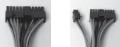
1. Connect the 24-pin Main Power Connector and the |
Picture 1 |
Picture 2 |
|
|
|
4-pin connector to the motherboard as needed. If the |
|
|
motherboard uses a 20-pin connector; detach the |
|
|
4-pin attachment on the 24-pin power connector |
|
|
(see pictures 1 and 2). |
For 24-pin |
For 20-pin |
Note: the detachable 4-pin section cannot be used in |
motherboards |
motherboards |
place of a 4-pin +12V connector. |
|
|
2.Connect the Reset switch (labeled RESET SW) to the motherboard at the RST connector. Polarity (positive and negative) does not matter for switches.
3.The Power Switch (labeled POWER SW) connects to the PWR connector on the motherboard.
4.The Power LED (labeled POWER LED) connector is located behind the Reset connector. For LEDs, colored wires are positive (+). White or black wires are negative (–). If the LED does not light up when the system is powered on, try reversing the connection. For more info on connecting LEDs to your motherboard, see your motherboard manual.
5.The Hard Drive LED (labeled HDD LED) connects to the hard drive activity header.
2
 Loading...