


 Loading...
Hardware Reference Guide
NI-700/900
NetLinx Integrated Controllers
|
|
|
|
NetLinx Integrated Controllers |
Last Revised: 5/13/2008 |
||
AMX Limited Warranty and Disclaimer
This Limited Warranty and Disclaimer extends only to products purchased directly from AMX or an AMX Authorized Partner which include AMX Dealers, Distributors, VIP’s or other AMX authorized entity.
AMX warrants its products to be free of defects in material and workmanship under normal use for three (3) years from the date of purchase, with the following exceptions:
•Electroluminescent and LCD Control Panels are warranted for three (3) years, except for the display and touch overlay components are warranted for a period of one (1) year.
•Disk drive mechanisms, pan/tilt heads, power supplies, and MX Series products are warranted for a period of one (1) year.
•AMX lighting products are guaranteed to switch on and off any load that is properly connected to our lighting products, as long as the AMX lighting products are under warranty. AMX also guarantees the control of dimmable loads that are properly connected to our lighting products. The dimming performance or quality there of is not guaranteed, impart due to the random combinations of dimmers, lamps and ballasts or transformers.
•AMX software is warranted for a period of ninety (90) days.
•Batteries and incandescent lamps are not covered under the warranty.
•AMX AutoPatch Epica, Modula, Modula Series4, Modula CatPro Series and 8Y-3000 product models will be free of defects in materials and manufacture at the time of sale and will remain in good working order for a period of three (3) years following the date of the original sales invoice from AMX. The three-year warranty period will be extended to the life of the product (Limited Lifetime Warranty) if the warranty card is filled out by the dealer and/or end user and returned to AMX so that AMX receives it within thirty (30) days of the installation of equipment but no later than six (6) months from original AMX sales invoice date. The life of the product extends until five (5) years after AMX ceases manufacturing the product model. The Limited Lifetime Warranty applies to products in their original installation only. If a product is moved to a different installation, the Limited Lifetime Warranty will no longer apply, and the product warranty will instead be the three (3) year Limited Warranty.
All products returned to AMX require a Return Material Authorization (RMA) number. The RMA number is obtained from the AMX RMA Department. The RMA number must be clearly marked on the outside of each box. The RMA is valid for a 30-day period. After the 30-day period the RMA will be cancelled. Any shipments received not consistent with the RMA, or after the RMA is cancelled, will be refused. AMX is not responsible for products returned without a valid RMA number.
AMX is not liable for any damages caused by its products or for the failure of its products to perform. This includes any lost profits, lost savings, incidental damages, or consequential damages. AMX is not liable for any claim made by a third party or by an AMX Authorized Partner for a third party.
This Limited Warranty does not apply to (a) any AMX product that has been modified, altered or repaired by an unauthorized agent or improperly transported, stored, installed, used, or maintained; (b) damage caused by acts of nature, including flood, erosion, or earthquake; (c) damage caused by a sustained low or high voltage situation or by a low or high voltage disturbance, including brownouts, sags, spikes, or power outages; or (d) damage caused by war, vandalism, theft, depletion, or obsolescence.
This limitation of liability applies whether damages are sought, or a claim is made, under this warranty or as a tort claim (including negligence and strict product liability), a contract claim, or any other claim. This limitation of liability cannot be waived or amended by any person. This limitation of liability will be effective even if AMX or an authorized representative of AMX has been advised of the possibility of any such damages. This limitation of liability, however, will not apply to claims for personal injury.
Some states do not allow a limitation of how long an implied warranty last. Some states do not allow the limitation or exclusion of incidental or consequential damages for consumer products. In such states, the limitation or exclusion of the Limited Warranty may not apply. This Limited Warranty gives the owner specific legal rights. The owner may also have other rights that vary from state to state. The owner is advised to consult applicable state laws for full determination of rights.
EXCEPT AS EXPRESSLY SET FORTH IN THIS WARRANTY, AMX MAKES NO OTHER WARRANTIES, EXPRESSED OR IMPLIED, INCLUDING ANY IMPLIED WARRANTIES OF MERCHANTABILITY OR FITNESS FOR A PARTICULAR PURPOSE. AMX EXPRESSLY DISCLAIMS ALL WARRANTIES NOT STATED IN THIS LIMITED WARRANTY. ANY IMPLIED WARRANTIES THAT MAY BE IMPOSED BY LAW ARE LIMITED TO THE TERMS OF THIS LIMITED WARRANTY. EXCEPT AS OTHERWISE LIMITED BY APPLICABLE LAW, AMX RESERVES THE RIGHT TO MODIFY OR DISCONTINUE DESIGNS, SPECIFICATIONS, WARRANTIES, PRICES, AND POLICIES WITHOUT NOTICE.

|
Table of Contents |
Table of Contents |
|
Introduction ........................................................................................................ |
1 |
NI-700 Overview....................................................................................................... |
1 |
NI-700 Specifications ................................................................................................ |
1 |
NI-700 Port Assignment And Functionality ..................................................................... |
4 |
NI-700 On-Board Memory Specifications ........................................................................ |
4 |
NI-900 Overview....................................................................................................... |
5 |
NI-900 Specifications ................................................................................................ |
5 |
NI-900 Port Assignment And Functionality ..................................................................... |
8 |
NI-900 On-Board Memory Specifications ........................................................................ |
9 |
TimeKeeper .............................................................................................................. |
9 |
Related Documents................................................................................................... |
9 |
Installation ........................................................................................................ |
11 |
Device:Port:System (D:P:S) ..................................................................................... |
11 |
Installing into an Equipment Rack........................................................................... |
11 |
Connections and Wiring ................................................................................... |
13 |
Setting the Configuration DIP Switch (for the Program Port) ................................. |
13 |
Baud Rate Settings........................................................................................................ |
13 |
Program Run Disable (PRD) Mode................................................................................. |
13 |
Working With the Configuration DIP Switch ................................................................. |
14 |
Program Port Connections and Wiring ................................................................... |
14 |
Modes and Front Panel LED Blink Patterns ............................................................ |
15 |
Port Assignments and Functionality........................................................................ |
15 |
AXlink Port and LED ............................................................................................... |
15 |
Wiring Guidelines ................................................................................................... |
16 |
Wiring Length Guidelines.............................................................................................. |
16 |
Preparing Captive Wires ............................................................................................... |
16 |
Wiring A Power Connection .......................................................................................... |
17 |
Using the 4-pin Mini-Phoenix Connector For Data and Power ...................................... |
17 |
Using the 4-pin Mini-Phoenix Connector For Data With External Power ...................... |
18 |
DB9 Device Port: Connections and Wiring ............................................................. |
18 |
IRX-RX Port: Connection and Wiring....................................................................... |
19 |
Input/Output (I/O) Port: Connections and Wiring................................................... |
20 |
IR/Serial Port: Connections and Wiring................................................................... |
21 |
Ethernet/RJ-45 Port: Connections and Wiring ........................................................ |
21 |
Ethernet LEDs .............................................................................................................. |
22 |
Ethernet Ports Used By the Integrated Controller ........................................................ |
23 |
NI-700 & NI-900 Hardware Reference Guide |
i |
|
|

Table of Contents
ii |
NI-700 & NI-900 Hardware Reference Guide |
|
|
Introduction
Introduction
NI-700 Overview
The NI-700 NetLinx Integrated Master Controller can be programmed to control RS-232/422/485, IR/ Serial, and Input/Output devices through the use of both the NetLinx programming language and the NetLinx Studio application (version 2.4 or higher). Another key feature of this product is the ability to easily access the configuration switches without having to remove a cover plate.
NetLinx Integrated Master Controller Features
NI-700 (FG2105-70)
•1 RS-232 Program port
•2 RS-232/RS-422/RS-485 ports
•1 IR/Serial Output ports
•4 Digital Input/Output ports
•1 IR RX (receive) port (works only with AMX IR Receivers)
When working with the NI-700 Integrated Controller, verify you are using the latest version of NetLinx Studio v 2.4 or higher (available for download from www.amx.com).
NI-700 Specifications
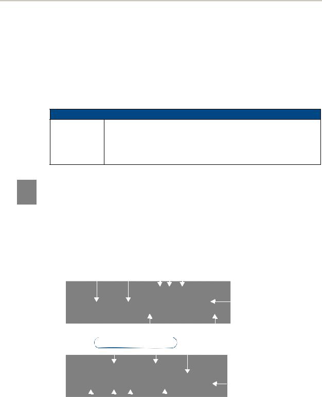
The front LEDs (FIG. 1) are grouped by control type and are labeled according to their corresponding port (connector) numbers on the rear of the unit.
Configuration |
|
|
|
|
IR LED (red) |
|||||||||||||||
|
DIP switch |
|
|
|
|
|
|
|
|
|
|
|
I/O LEDs (yellow) |
|||||||
Program |
|
|
|
|
|
|
|
|
|
|
||||||||||
|
|
|
|
|
|
|
|
|
|
Serial RS-232/422/485 TX/RX LEDs (red/yellow) |
||||||||||
port |
|
|
|
|
|
|
|
|
|
|
|
|
|
|
|
|
|
|
|
Link/Active-Status-Output-Input |
Front |
|
|
|
|
|
|
|
|||||||||||||
|
|
|
|
|
|
|
||||||||||||||
|
|
|
|
|
|
|
|
|
|
|
|
|
|
|
|
|
|
|
|
(green/red/yellow) |
|
|
IR RX LED (red) |
|
|
|
|
|
|
ID Pushbutton |
|||||||||||
|
|
|
|
|
|
|
|
|
||||||||||||
|
|
|
|
|
|
|
|
|||||||||||||
|
|
RS |
|
|
|
|
|
1 & 2) |
|
|
|
|
|
|
|
|
||||
|
|
- |
232/422/485 (Ports |
|
|
Ethernet |
||||||||||||||
|
|
|
|
|
|
|
|
|
|
|
|
|
|
|
||||||
|
|
|
|
|
|
|
|
|
|
|
|
|
|
|
|
|
|
|
|
|
Rear
|
|
|
|
|
|
|
|
Power |
IR RX |
|
I/O |
|
|
|
IR/Serial |
|
AXlink port/LED |
|
|
|
|
|
||||
|
|
|
|
|
||||
|
|
|
|
|||||
(Port 5) |
(Port 4) |
|
|
(Port 3) |
|
|
||
FIG. 1 NI-700 NetLinx Integrated Controller
NI-700 & NI-900 Hardware Reference Guide |
1 |
|
|

Introduction
NI-700 Specifications
Dimensions (HWD): |
• 1.58" x 5.54" x 5.12" (4.01 cm x 14.10 cm x 13.00 cm) |
|
• 1 RU (rack unit) high |
|
|
Power Requirements: |
• 280 mA @ 12 VDC |
|
|
Memory: |
See the NI-700 On-Board Memory Specifications section on page 4. |
|
|
Microprocessor: |
• 304 MIPS |
|
|
Weight: |
• 1.30 lbs (0.59 kg) |
|
|
Enclosure: |
• Metal with black matte finish |
|
|
Certifications: |
• FCC Part 15 Class B, CE, and IEC 60950 |
|
|
Front Panel Components: |
|
|
|
Program port |
• RS-232 DB9 connector (male) can be connected to a DB9 port on a computer. |
|
This port can be used with both Serial and NetLinx programming commands. It is |
|
also used to both upload and download information from the NetLinx Studio 2.4 |
|
program. |
|
|
Configuration DIP switch |
• Sets the communication parameters for the Program port. |
|
|
IR RX LED |
• Red LED lights to when IR data is being received via the rear IR RX port. |
|
|
IR LED |
• Red LED lights during the transmission of IR or Serial data via the rear IR port. |
|
|
I/O LEDs |
• Four yellow LEDs light when the rear I/O channels 1-4 are active. LED indicator |
|
for each I/O port reflects the state of that particular port. |
|
|
Serial LEDs |
• Two sets of red and yellow LEDs light when the rear DB9 Ports (1 & 2) are |
|
transmitting or receiving RS-232, 422, or 485 data: |
|
- TX LEDs (red) light when transmitting data |
|
- RX LEDs (yellow) light when receiving data |
|
- LED activity reflects transmission and reception activity |
|
• These LEDs do not reflect changes in either the RTS or CTS when hardware |
|
handshaking is used. |
|
|
LINK/ACT |
• Green LED lights when the Ethernet cable is connected and an active link is |
|
established. This LED also blinks when receiving Ethernet data packets. |
|
|
Status |
• Green LED lights when the Controller is programmed and communicating |
|
properly. |
|
|
Output |
• Red LED lights when the Controller transmits data, sets channels On/Off, sends |
|
data strings, etc. |
|
|
Input |
• Yellow LED lights when the Controller receives data from button pushes, strings, |
|
commands, channel levels, etc. |
|
|
ID pushbutton |
Provides the NetLinx ID (D:S) assignment for the device. |
|
• The D notation is used to represent a device number. |
|
• The S notation is used to represent the System number of the Master. |
|
Refer to the NetLinx Integrated Controller WebConsole & Programming Guide for |
|
details. |
|
|
Rear Panel Connectors: |
|
|
|
RS-232/422/485 |
• Two RS-232/422/485 control ports using DB9 (male) connectors with |
(Ports 1 & 2) |
XON/XOFF (transmit On/transmit Off), CTS/RTS (clear to send/ready to send), |
|
and 300 - 115,200 baud. |
|
• Channel range = 1 - 255 |
|
• Channels 1 - 254 provide feedback |
|
• Channel 255 (CTS Push channel): Reflects the state of the CTS Input if a |
|
'CTSPSH' command was sent to the port |
|
• Output data format for each port is selected via software |
|
• Two DB9 connectors provide RS-232/422/485 termination |
|
|
2 |
NI-700 & NI-900 Hardware Reference Guide |

Introduction
NI-700 Specifications (Cont.)
Rear Panel Components (Cont.):
IR RX |
• 4-pin 3.5 mm mini-Phoenix port is used to connect one or more (8 maximum) |
(Port 5) |
IRX-SM+ swivel mount or IRX-DM+ Decora mount IR receivers. |
|
• The IR RX port functions using AMX IR codes (38 KHz and 455 KHz) and works |
|
ONLY with AMX IR Receivers such as the IRX-DM+ and IRX-SM+. |
|
|
Digital I/O |
• Four-channel binary I/O port for contact closure with each input being capable of |
(Port 4) |
voltage sensing. |
|
• Input format is software selectable. |
|
• Interactive power sensing for IR ports |
|
• Channel range = 1 - 4 |
|
• All inputs are assigned to respective IR/Serial ports for "automatic" power control |
|
through the use of software commands. Power control is provided via |
|
commands such as: ’PON’, ’POF’, ’POD’, ’DELAY’, I/O Link etc.). |
|
• Contact closure between GND and an I/O port is detected as a PUSH |
|
• When used as voltage input - I/O port detects a low signal (0- 1.5 VDC) as a |
|
PUSH and a high signal (3.5 - 5 VDC) as a RELEASE |
|
• When used as an output - each I/O port acts as a switch to GND and is rated at |
|
200 mA @ 12 VDC |
|
• Single 6-pin 3.5 mm mini-Phoenix (female) connector provides I/O port |
|
termination |
|
Note: This IO uses 5V logic but can handle up to 12V without harm. It can handle |
|
up to 12V on the input. At higher voltages you run a higher risk of surge damage. |
|
|
IR/Serial |
• 4-pin 3.5 mm mini-Phoenix port is capable of generating IR with the use of an IR |
(Port 3) |
Emitter (while in IR mode). This port can support high-frequency carriers of up |
|
to 1.142 MHz and can also generate IR with no carrier frequency. |
|
• The output is capable of three electrical formats: IR, Serial, and Data |
|
• Single IR/Serial signal can be generated. |
|
• Channel range = 1 - 255 |
|
• Channels 1 - 128 (output): IR commands |
|
• Channels 129 - 253: used as reference channels |
|
• Channel 254 (feedback): Power Fail (used with 'PON' and 'POF' commands) |
|
• Channel 255 (feedback): Power status (when IO Link is set) |
|
• IR ports support data mode (at limited baud rates and wiring distances). |
|
• Single 2-pin 3.5 mm mini-Phoenix (female) connector provides IR port |
|
termination |
|
|
AXlink LED |
• Green LED indicates the state of the AXlink connector port. |
|
• Normal AXlink activity = 1 blink/second |
|
• Abnormal AXlink activity = cycle of 3 consecutive blinks and then Off |
|
|
AXlink port |
• 4-pin 3.5 mm mini-Phoenix (male) connector provides data and power to external |
|
control devices. |
|
|
Ethernet port |
• RJ-45 port for 10/100 Mbps communication. The Ethernet Port automatically |
|
negotiates the connection speed (10 Mbps or 100 Mbps) and whether to use half |
|
duplex or full duplex mode. |
|
|
Ethernet Link/ |
• Ethernet Port: RJ-45 port for 10/100 Mbps communication. LEDs show |
Activity LED |
communication activity, connection status, speeds, and mode information: |
|
SPD (speed) - Yellow LED lights On when the connection speed is 100 Mbps and |
|
turns Off when the speed is 10 Mbps. |
|
L/A (link/activity) - Green LED lights On when the Ethernet cables are connected |
|
and terminated correctly, and blinks when receiving Ethernet data packets. |
|
|
Power port |
• 2-pin 3.5 mm mini-Phoenix (male) connector. |
|
• Use a 12 VDC-compliant power supply to provide power to the NI-700 through |
|
the 2-pin 3.5 mm mini-Phoenix connector on the rear panel. |
|
|
NI-700 & NI-900 Hardware Reference Guide |
3 |
|
|

Introduction
NI-700 Specifications (Cont.)
Operating Environment: |
• Operating Temperature: 0° C (32° F) to 50° C (122° F) |
|
• Operating Humidity: 20% - 85% RH |
|
|
Included Accessories: |
• 2-pin 3.5 mm mini-Phoenix female PWR connector (41-5025) |
|
• 4-pin 3.5 mm mini-Phoenix female connector (41-5047) |
|
• 6-pin 3.5 mm mini-Phoenix female I/O connector (41-5063) |
|
• CC-NIRC IR Emitter |
|
• NI-700 Quick Start Guide |
|
|
Other AMX Equipment: |
• AC-RK Accessory Rack Kit (FG515) |
|
• CC-NIRC IR cables (FG10-000-11) |
|
• CC-NSER IR/Serial cables (FG10-007-10) |
|
• CSB Cable Support Bracket (FG517) |
|
• IRX-DM+ IR Sensor (FG458-10 and FG458-11) |
|
• IRX-SM+ IR Sensor (FG455-01) |
|
• PMB Pole Mount Bracket (FG531) |
|
• STS, Serial To Screw Terminal (FG959) |
|
• Surface Mount Bracket Accessory (FG525) |
|
|
NI-700 Port Assignment And Functionality
NI-700 Port Assignments
Port |
ICSP Port # |
|
|
Serial Port #1 |
1 |
|
|
Serial Port #2 |
2 |
|
|
IR Port |
3 |
|
|
I/O Port |
4 |
|
|
IR RX Port |
5 |
|
|
NI-700 On-Board Memory Specifications
There are two variations on the NI-700, with different memory specifications. The latest version of the NI-700 has double the on-board memory of previous versions.
The latest version of the NI-700 is FG2105-70
Previous versions of the NI-700 are FG2105-03
NI-700 On-Board Memory Specifications
FG2105-70 • 64 MB SDRAM (not upgradeable)
•32 MB Flash chip (not upgradeable)
•512 Kb of Non-volatile SRAM
FG2105-03 • 32 MB SDRAM (not upgradeable)
•16 MB Flash chip (not upgradeable)
•512 Kb of Non-volatile SRAM
4 |
NI-700 & NI-900 Hardware Reference Guide |

Introduction
NI-900 Overview
The NI-900 is the first NetLinx device to be Duet-compatible straight out of the box. Duet is a dual-interpreter firmware platform from AMX which combines the proven reliability and power of NetLinx with the extensive capabilities of the Java®2 MicroEdition (J2ME) platform. Duet simplifies the programming of a system that includes the NI-900 and other third party devices by standardizing device and function definitions, defaulting touch panel button assignments, and controlling feedback methods. Dynamic Device Discovery makes integration even easier by automatically identifying and communicating with devices which support this new beaconing technology.
The NI-900 unit (FG2105-09) is geared to meet the specific control and automation needs of a single room environment requiring the control of several IR devices, where both price and functionality are the driving requirement. This product is configured to control a limited number of video players, projectors, lighting, thermostats, and other electronic equipment.
NetLinx Integrated Master Controller Features
NI-900 (FG2105-90)
•1 RS-232 Program port
•1 RS-232/RS-422/RS-485 ports
•3 IR/Serial Output ports
•4 Digital Input/Output ports
•1 IR RX (receive) port (works only with AMX IR Receivers)
When working with the NI-900 Integrated Controller, verify you are using the latest version of NetLinx Studio v 2.4 or higher (available for download from www.amx.com).
NI-900 Specifications
The front LEDs (FIG. 2) are grouped by control type, and are numbered according to their corresponding port (connector) numbers on the rear of the unit.
Configuration |
|
|
|
|
IR LED (red) |
||||||||||||
|
DIP switch |
|
|
|
|
|
|
|
|
|
|
I/O LEDs (yellow) |
|||||
Program |
|
|
|
|
|
|
|
|
|||||||||
|
|
|
|
|
|
|
|
Serial RS-232/422/485 TX/RX LEDs (red/yellow) |
|||||||||
port |
|
|
|
|
|
|
|
|
|
|
|
|
|
|
|
|
Link/Active-Status-Output-Input |
Front |
|
|
|
|
|
|
|
||||||||||
|
|
|
|
|
|
|
|||||||||||
|
|
|
|
|
|
|
|
|
|
|
|
|
|
|
|
|
(green/red/yellow) |
|
|
IR RX LED (red) |
|
|
|
|
|
|
ID Pushbutton |
||||||||
|
|
|
|
|
|
|
|
|
|||||||||
|
|
|
|
|
|
|
|
||||||||||
RS-232/422/485 (Port 1) |
|
|
|
|
|
|
Ethernet |
||||||||||
|
|
|
|
|
|
|
|
||||||||||
|
|
|
|
|
|
|
|
|
|
|
|
|
|
|
|
|
|
Rear
|
|
|
|
|
|
|
|
Power |
IR RX |
|
I/O |
|
|
|
IR/Serial |
|
AXlink port/LED |
|
|
|
|
|
||||
|
|
|
|
|
||||
|
|
|
|
|||||
(Port 6) |
(Port 5) |
|
(Ports 2-4) |
|
|
|||
FIG. 2 NI-900 NetLinx Integrated Controller
NI-700 & NI-900 Hardware Reference Guide |
5 |
|
|
Loading...