


 Loading...
instruction manual
AXP-PLV
PosiTrack Pilot Video Camera Controller (Firmware version G3)
Camera Control Systems
AMX Limited Warranty and Disclaimer
AMX Corporation warrants its products to be free of defects in material and workmanship under normal use for three (3) years from the date of purchase from AMX Corporation, with the following exceptions:
•Electroluminescent and LCD Control Panels are warranted for three (3) years, except for the display and touch overlay components that are warranted for a period of one (1) year.
•Disk drive mechanisms, pan/tilt heads, power supplies, MX Series products, and KC Series products are warranted for a period of one (1) year.
•Unless otherwise specified, OEM and custom products are warranted for a period of one (1) year.
•Software is warranted for a period of ninety (90) days.
•Batteries and incandescent lamps are not covered under the warranty.
This warranty extends only to products purchased directly from AMX Corporation or an Authorized AMX Dealer.
AMX Corporation is not liable for any damages caused by its products or for the failure of its products to perform. This includes any lost profits, lost savings, incidental damages, or consequential damages. AMX Corporation is not liable for any claim made by a third party or by an AMX Dealer for a third party.
This limitation of liability applies whether damages are sought, or a claim is made, under this warranty or as a tort claim (including negligence and strict product liability), a contract claim, or any other claim. This limitation of liability cannot be waived or amended by any person. This limitation of liability will be effective even if AMX Corporation or an authorized representative of AMX Corporation has been advised of the possibility of any such damages. This limitation of liability, however, will not apply to claims for personal injury.
Some states do not allow a limitation of how long an implied warranty last. Some states do not allow the limitation or exclusion of incidental or consequential damages for consumer products. In such states, the limitation or exclusion of the Limited Warranty may not apply. This Limited Warranty gives the owner specific legal rights. The owner may also have other rights that vary from state to state. The owner is advised to consult applicable state laws for full determination of rights.
EXCEPT AS EXPRESSLY SET FORTH IN THIS WARRANTY, AMX CORPORATION MAKES NO OTHER WARRANTIES, EXPRESSED OR IMPLIED, INCLUDING ANY IMPLIED WARRANTIES OF MERCHANTABILITY OR FITNESS FOR A PARTICULAR PURPOSE. AMX CORPORATION EXPRESSLY DISCLAIMS ALL WARRANTIES NOT STATED IN THIS LIMITED WARRANTY. ANY IMPLIED WARRANTIES THAT MAY BE IMPOSED BY LAW ARE LIMITED TO THE TERMS OF THIS LIMITED WARRANTY.

Table of Contents
Table of Contents |
|
Introduction ............................................................................................................... |
1 |
Specifications .................................................................................................................... |
1 |
Product Components......................................................................................................... |
2 |
Sample Product Application .............................................................................................. |
3 |
Installation ................................................................................................................. |
5 |
Inside the AXP-PLV........................................................................................................... |
5 |
Setting the AXlink Device Numbers .................................................................................. |
5 |
Wiring the AXP-PLV .......................................................................................................... |
6 |
Wiring guidelines...................................................................................................................... |
6 |
Using the mini-XLR connector for AXlink data and power ....................................................... |
7 |
Using the mini-XLR connector with an external 12 VDC power supply ................................... |
7 |
Using a BNC video cable to provide video input ...................................................................... |
7 |
Designing Touch Panel Pages ................................................................................ |
9 |
Buttons .............................................................................................................................. |
9 |
Activating Edit Mode........................................................................................................ |
10 |
Setting the Device Base .................................................................................................. |
12 |
Setting the Device Used.................................................................................................. |
12 |
Adding a Page................................................................................................................. |
12 |
Setting the page color ............................................................................................................ |
13 |
Adding a Button............................................................................................................... |
13 |
Resizing a button ................................................................................................................... |
13 |
Defining On-Screen and External Button Properties....................................................... |
13 |
Setting the channel code........................................................................................................ |
14 |
Setting the variable text code................................................................................................. |
14 |
Setting the page flip ............................................................................................................... |
14 |
Setting the button colors for channel-off conditions ............................................................... |
15 |
Adding text, icons, and bitmaps to a button ........................................................................... |
15 |
Using TPDesign3 to Download Bitmaps, Icons, and Fonts............................................. |
15 |
Creating a Bargraph and Joystick ................................................................................... |
16 |
Adding a bargraph or joystick button\..................................................................................... |
16 |
Setting Bargraph and Joystick Properties ....................................................................... |
16 |
Setting the level code............................................................................................................. |
17 |
Programming .......................................................................................................... |
19 |
Serial Commands............................................................................................................ |
19 |
System Send_Commands............................................................................................... |
20 |
AXP-PLV PosiTrack Pilot VIdeo Camera Controller |
i |
|
|
|
|

Table of Contents
Video Send_Commands ................................................................................................. |
25 |
AXP-AI8 Send_Commands............................................................................................. |
26 |
Programming Numbers ................................................................................................... |
27 |
Shorthand Send_Commands.......................................................................................... |
28 |
Color Send_Commands.................................................................................................. |
32 |
Variable Text Send_Commands ..................................................................................... |
34 |
Shorthand Variable Text Commands .............................................................................. |
36 |
Button String Commands ................................................................................................ |
39 |
Upgrading The Firmware ....................................................................................... |
41 |
PosiTrack Pilot FG to TSK file relation................................................................................... |
41 |
Upgrading the Firmware Using NetLinx Studio ............................................................... |
42 |
Upgrading Firmware through a COM port.............................................................................. |
42 |
Upgrading the Firmware through an IP Address.................................................................... |
44 |
Upgrading the Firmware Using SoftROM........................................................................ |
47 |
Configuration.......................................................................................................................... |
47 |
Downloading the Firmware .................................................................................................... |
48 |
|
ii |
AXP-PLV PosiTrack Pilot Video Camera Controller |
|
|
|
Introduction
Introduction
The AXP-PLV PosiTrack Pilot Video Panel Camera Controller (PosiPilot) is an integrated controller for use with cameras and camera positioning devices (such as the AXB-PT15 PosiTrack Camera Controllers). Refer to the AXB-PT15 PosiTrack Camera Controller instruction manual for more information. The AXP-PLV connects to the camera-positioning device and Central Controller via an AXlink connection. This connection provides control of the pan/tilt, camera, and lens. The PosiPilot can be used in a stand-alone configuration with a Central Controller, compatible cameras, and positioning systems, or as part of a larger AMX control system.
The PosiPilot combines traditional dual-axis proportional-speed joystick camera controls with an integrated Color Active Mini-Touch Panel to give you graphic touch control and on-screen video monitoring (with video input for NTSC/PAL).
Specifications
Specifications
Dimensions (HWD) |
4.97" (including joysticks) x 17.67" x 8.39" (12.61 cm x 44.89 cm x 21.30 cm) |
|
|
Weight |
4.90 lb (2.20 kg) |
|
|
Power |
825 mA |
|
|
Enclosure |
Plastic with matte blue finish and plastic rests |
|
|
Temperature Range |
0º C (32º F) to 50º C (122º F) |
|
|
Power Consumption |
1 A @12 VDC |
|
|
Buttons |
12 pushbuttons, six on each side to select cameras and access camera menus |
|
|
Video monitor |
6-inch (152.40 mm) color active-matrix LCD screen |
|
|
Video In |
BNC female connector (NTSC/PAL) |
|
|
Compatibility |
NetLinx/Axcess Central Controllers |
|
|
Connectors |
• 4-pin mini-XLR (female) cable (pre-assembled) |
|
• BNC (female) Video In connector (NTSC/PAL) |
|
|
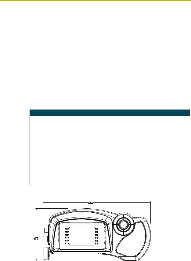
FIG. 1 and FIG. 2 show the dimensions for the front and side of the AXP-PLV.
FIG. 1 AXP-PLV front panel dimensions
AXP-PLV PosiTrack Pilot Video Camera Controller |
1 |
|
|
|
|
Introduction
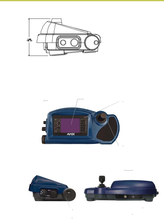
FIG. 2 AXP-PLV side panel dimensions
Product Components
The top of the PosiPilot is equipped with external pushbuttons, color video touch panel, and a 3-axis pan/tilt/zoom joystick. FIG. 3 gives a description of the AXP-PLV front panel components.
|
|
|
|
Color video touch |
External |
|
panel for video preview |
||
pushbuttons |
|
and control interface |
||
|
|
|
|
|
|
|
|
|
|
|
|
|
|
|
FIG. 3 AXP-PLV front panel component descriptions
FIG. 4 gives a description of the side and rear components.
Focus control knob
Iris control knob
Speed knob
External pushbuttons
Pan/tilt/zoom control joystick
Pan/tilt/zoom control joystick
Mini-XLR (male)
BNC (male)
FIG. 4 AXP-PLV side and rear component descriptions
|
2 |
AXP-PLV PosiTrack Pilot Video Camera Controller |
|
|
|
Introduction
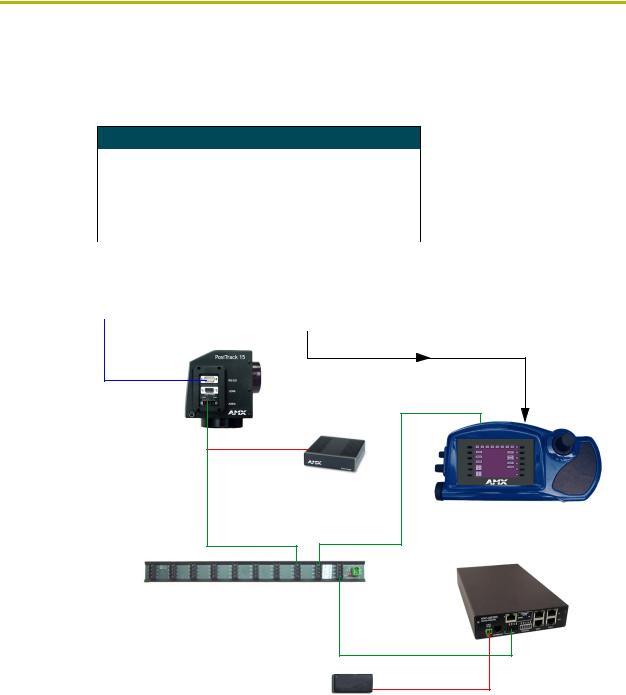
Sample Product Application
FIG. 5 shows a camera control application using the AXP-PLV. AMX devices used for a single
camera configuration are:
Sample Devices Used
NXC-ME260 |
NetLinx Master Controller |
|
|
|
|
|||||
|
|
|
|
|
|
|
|
|
|
|
AXB-PT15 |
Pan/Tilt Camera Head |
|
|
|
|
|||||
|
|
|
|
|
|
|
|
|
|
|
AXP-PLV |
PosiTrack Pilot Video Panel Camera Controller |
|
||||||||
|
|
|
|
|
|
|
|
|
|
|
PS2.8 |
Power Supply (for AXB-EM232) |
|
||||||||
|
|
|
|
|
|
|
|
|
|
|
PSN6.5 |
Power Supply (for AXB-PT15) |
|
|
|
|
|||||
|
|
|
|
|
|
|
|
|
|
|
|
|
|
|
|
|
|
|
|
|
|
|
|
|
|
|
|
|
|
|
|
|
|
|
Camera Adapter |
|
|
|
Camera |
|
|
|
|
|
|
|
|
|
|
|
|
|||
|
|
|
|
|
|
|
|
|
|
|
|
|
|
|
|
|
|
|
|
|
|
|
DB-9 |
|
|
|
|
|
|
|
|
|
Preview input
AMX AXB-PT-15
2-pin captive-wire
AMX PSN6.5
Power Supply
AMX AXP-PLV
AXlink |
AXlink |
AMX NXC-ME260 (rear view)
AMX ABS (AXlink Bus Strip)
AXlink
2-pin captive-wire
AMX PS2.8
Power Supply
FIG. 5 AXB-PLV product application
AXP-PLV PosiTrack Pilot Video Camera Controller |
3 |
|
|
|
|

Introduction
|
4 |
AXP-PLV PosiTrack Pilot Video Camera Controller |
|
|
|
Installation
Installation
Inside the AXP-PLV
The AXP-PLV unit contains two discrete AXlink devices: an AXP-AI8 (eight-channel analog input interface board) and a mini color video touch panel. The AXP-AI8 is connected to the joystick and knob functions of the AXP-PLV and is set to a factory default of 129.
Level assignments for the AXP-AI8 inside the AXP-PLV are:
AXP-AI8 Level Assignments
Level 1 |
Pan (joystick) |
|
|
Level 2 |
Tilt (joystick) |
|
|
Level 3 |
Zoom (joystick) |
|
|
Level 4 |
Speed (knob) |
|
|
Level 5 |
Iris (knob) |
|
|
Level 7 |
Focus (knob) |
|
|
Refer to the AXP-AI8 Eight-Channel Analog Input Interface Board instruction manual for more
information.
Setting the AXlink Device Numbers
To change the AXP-AI8 AXlink device number:
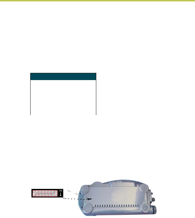
1.Gently rotate the panel (bringing the joystick to the left) over until you can lay it down and expose the slender opening on the underside of the unit. The slot exposes the AXlink DIP switch on the internal AI8 circuit card) (FIG. 6).
8 7 6 5 4 3 2 1
AXlink DIP switch (S5)
FIG. 6 AI8 AXlink DIP switch location (default set to 129)
2.Use a slender screwdriver to change the internal DIP switch positions from their default value of 129 (FIG. 6).
The DIP switch value set on the underside of the controller is the value assigned to the internal AI8 card (default 129). The touch panel is default set to 131. When the unit is connected to a Central Controller and queried for its addresses, it returns a value for both the touch panel (default 131) and the AI8 card (default 129).
AXP-PLV PosiTrack Pilot Video Camera Controller |
5 |
|
|
|
|
Installation
3.Set the AXlink device number by changing the AXlink device DIP switch positions 1 – 8 (FIG. 6). The total value of all ON (up) positions on the DIP switch sets the device number. The DIP switch value range is between 1 - 255, and is set according to the Device DIP switch positions and their corresponding values. The device number takes effect only after powering-up.
Device DIP Switch Settings
Position |
1 |
2 |
3 |
4 |
5 |
6 |
7 |
8 |
|
|
|
|
|
|
|
|
|
On value |
1 |
2 |
4 |
8 |
16 |
32 |
64 |
128 |
|
|
|
|
|
|
|
|
|
4.Once completed, rotate the unit and lay it on a flat surface. Refer to the Setting the Device Base section on page 12 for more information on changing the touch panel device number.
Wiring the AXP-PLV
The AXP-PLV has an AXlink four-wire mini-XLR connector (located on the rear of the AXP-PLV) and a BNC male connector (at the rear of the unit) A female mini-XLR cable (provided) is supplied to facilitate wiring.
Wiring guidelines
The AXP-PLV requires 12 VDC power to operate properly. The Central Controller supplies power via the AXlink cable or external auxiliary 12 VDC power supply. The maximum wiring distance between the Central Controller and AXP-PLV is determined by power consumption, supplied voltage, and the wire gauge used for the cable. The Wiring Guidelines@825 mA tablelists wire sizes and the maximum lengths allowable between the camera centers and control system. The maximum wiring lengths for using AXlink power are based on a minimum of 13.5 VDC available at the control system’s power supply.
Wiring Guidelines@825 mA
Wire size |
Maximum wiring length |
|
|
18 AWG |
142.27 feet (43.36 m) |
|
|
20 AWG |
90.01 feet (27.43 m) |
|
|
22 AWG |
56.12 feet (17.10 m) |
|
|
24 AWG |
35.37 feet (10.78 m) |
|
|
If you install the AXP-PLV farther away from the control system than recommended in the above table, connect an external 12 VDC power supply to the camera controller according to the wiring diagrams described in this section.
|
6 |
AXP-PLV PosiTrack Pilot Video Camera Controller |
|
|
|
Installation
Using the mini-XLR connector for AXlink data and power
Wire the Central Controller’s AXlink connector to the mini-XLR connector (male) on the rear panel of the AXP-PLV for data and 12 VDC power, as shown in FIG. 7.
Four-pin mini-XLR connector (external view)
|
2 |
|
|
1 GND (-) |
- Black |
1 |
4 |
3 |
|
2 AXM |
- Green |
|
3 AXP |
- White |
|||
|
|
|
|||
|
|
|
|
||
|
|
|
|
4 PWR (+) - Red |
|
4 |
- PWR (+) - Red |
Central Controller |
|
||
3 |
- AXP |
|
- White |
|
|
|
(Axcess or NetLinx) |
|
|||
2 |
- AXM |
- Green |
|
||
|
|
||||
1 - GND (-) - Black
FIG. 7 Mini-XLR connector to control system wiring diagram
Using the mini-XLR connector with an external 12 VDC power supply
Wire the Central Controller’s AXlink connector to the mini-XLR connector and external 12 VDC power supply. Then, connect the mini-XLR terminal connector to the rear panel of the AXP-PLV as shown in FIG. 8.
|
|
|
|
|
|
|
|
|
|
|
|
|
|
|
|
|
|
|
|
|
|
|
|
|
|
PWR (+) - Red |
|
|||
|
|
|
|
|
|
|
|
|
|
|
|
|
Four-pin mini-XLR connector |
|
|
|
|
|
|
GND (-) - Black |
||||||||||
|
|
|
|
|
|
|
|
|
|
|
|
|
|
|
|
|
|
|
||||||||||||
|
|
|
|
|
|
|
|
|
|
|
|
|
|
|
|
|
|
|
|
|
|
|
|
|||||||
|
|
|
|
2 |
|
|
|
|
|
|
|
(external view) |
|
|
|
|
|
|
|
|
|
GND (-) |
- Black |
|||||||
|
|
|
|
|
|
|
|
|
|
|
|
|
|
|
|
|
|
|
|
|
|
|
|
|
|
|||||
|
|
|
|
|
|
|
|
|
|
|
|
|
|
|
|
|
|
|
|
|
|
|
|
1 |
||||||
|
1 |
4 |
3 |
|
|
|
|
|
|
|
|
|
|
|
|
|
|
|
|
|
|
2 |
AXM |
- Green |
||||||
|
|
|
|
|
|
|
|
|
|
|
|
|
|
|
|
|
|
|
|
|
|
|
|
|
|
|
|
3 |
AXP |
- White |
|
|
|
|
|
|
|
|
|
|
|
|
|
|
|
|
|
|
|
|
|
|
|
|
|
|
|
|
4 |
PWR (+) - Red |
|
|
|
4 - PWR (+) - Red |
|
|
|
|
|
|
|
|
||||||||||||||||||||
|
|
|
|
Central Controller |
|
|||||||||||||||||||||||||
|
|
3 - AXP |
|
- White |
|
|
|
|||||||||||||||||||||||
|
|
2 - AXM |
|
- Green |
|
(Axcess or NetLinx) |
|
|||||||||||||||||||||||
|
|
1 - GND (-) - Black |
|
|
|
|
|
|
|
|
|
|
|
|||||||||||||||||
FIG. 8 |
Mini-XLR connector to external 12 VDC power supply wiring diagram |
|
|
|
|
|
|
|
|
|
|
|
||||||||||||||||||
Using a BNC video cable to provide video input
Connect the control system’s video connector to the rear of the AXP-PLV using a BNC cable to
provide a video feed, as seen in FIG. 9.
BNC (female) connector |
|
|
|
|
|
|
|
GND (-) |
|||||||||||||||||||
|
|
|
|
|
Video wire |
||||||||||||||||||||||
|
|
|
|
|
|
|
|
|
|
|
|
|
|
|
|
|
|
|
|
|
|
||||||
|
|
|
|
|
|
|
|
|
|
|
|
|
|
|
|
|
|
|
|
|
|
|
|
|
|
|
|
|
|
|
|
|
|
|
|
|
|
|
|
|
|
|
|
|
|
|
|
|
|
|
|
|
|
|
|
|
|
|
|
|
|
|
|
|
|
|
|
|
|
|
|
|
|
|
|
|
|
|
|
|
|
|
|
|
|
|
|
|
|
|
|
|
|
|
|
|
|
|
|
|
|
|
|
|
|
|
|
|
|
|
|
|
|
|
|
|
|
|
|
|
|
|
|
|
|
|
|
|
|
|
|
|
|
|
|
|
|
|
|
Rear panel  BNC (male) connectors
  Video source view AXP-PLV
FIG. 9 BNC cable connection from the AXP-PLV to the video source
AXP-PLV PosiTrack Pilot Video Camera Controller |
7 |
|
|
|
|

Installation
|
8 |
AXP-PLV PosiTrack Pilot Video Camera Controller |
|
|
|

Designing Touch Panel Pages
Designing Touch Panel Pages
There are two ways to approach creating touch panel pages:
TPDesign3 - Refer to the TPDesign3 Touch Panel Program (Version 3. 16) instruction manual for more information.
On-board editor
This section describes the basics of using the on-board editor to create pages and buttons. For more information, refer to the G3 Firmware Design and Reference instruction manual.
Buttons
Standard button types include rectangles and other geometric shapes you can create with the touch panel editor. Buttons are set with attributes, meaning there is a response from the Central Controller when you touch the button.
General buttons are part of the default touch panel program and cannot be changed. You use general buttons to create or revise pages and specify panel communication parameters. Button examples include selection buttons, information buttons, adjustment buttons, and operation bars. The general button categories are described in the table below.
General Button Categories
Selection buttons |
Selection buttons appear on touch panel pages and set communica- |
|
tion parameters. |
|
|
Information buttons |
Information buttons contain serial numbers and firmware version |
|
information. The properties of these buttons cannot be changed. |
|
These buttons have a dark fill and light text. |
|
|
Adjustment buttons |
You can use the UP and DN buttons to set adjustment buttons. The |
|
adjustment button example sets the baud rate for the connection |
|
from the touch panel to the computer. |
Keypad buttons |
The keypad button opens a keypad so you can enter a password or |
|
value assignment. All keypad buttons are interactive except for the |
|
entry display. |
Decision buttons |
Decision buttons appear when an operation has two options and |
|
requires verification before an action is performed. |
AXP-PLV PosiTrack Pilot Video Camera Controller |
9 |
|
|
|
|
Designing Touch Panel Pages
General Button Categories (Cont.)
Status buttons |
Status buttons always have a dark fill with light letters and have no |
|
functionality except to display information. |
|
|
Operation bars |
Operation bars appear in the place of the Editor bar, after selecting a |
|
button or page edit operation. The operation bar indicates which edit |
|
function is currently active. When an edit operation is selected, it |
|
remains active until you press EXIT. |
|
|
Touch to Continue buttons |
"Touch to Continue" buttons appear when an operation requires user |
|
acknowledgement. |
|
|
Joystick buttons |
Joysticks are vertical and horizontal direction controllers for use with |
|
pan and tilt camera controllers. |
|
|
Bargraph buttons |
Bargraph buttons display a dynamic bargraph (vertical or horizontal). |
|
An example is the Battery level indicator button. |
|
|
Activating Edit Mode
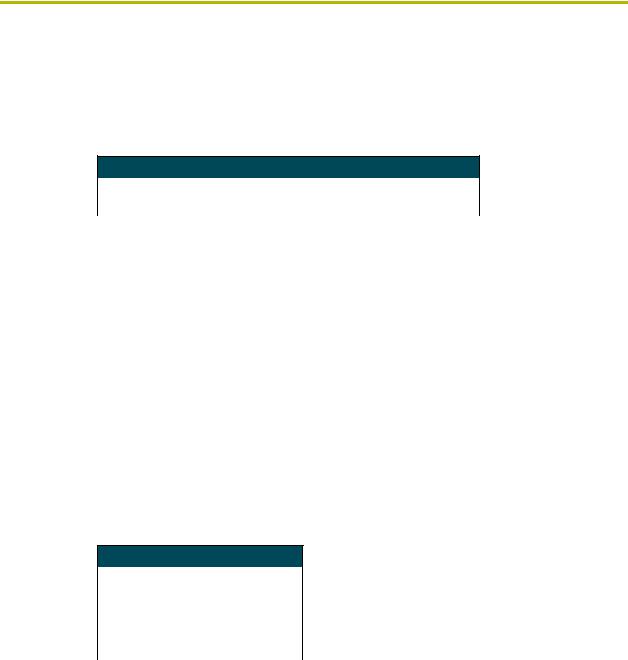
Before designing touch panel pages and buttons, you must activate EDIT mode. Once activated, use the EDIT button to enter Edit mode. This mode has options to add and configure touch panels and buttons. When powering up the touch panel, the first page is the Main page (see FIG. 10). Note that the Edit button is not available initially.
FIG. 10 Main Page
If you have a pre-programmed panel, you may not see the Main Page.
|
10 |
AXP-PLV PosiTrack Pilot Video Camera Controller |
|
|
|
Designing Touch Panel Pages
To activate edit mode:
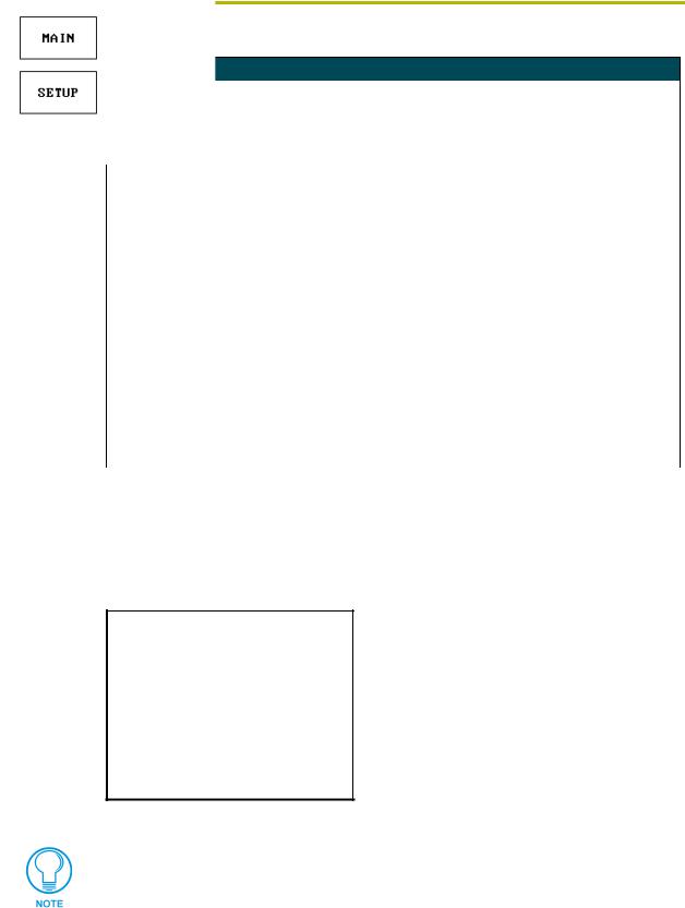
1. Press SETUP in the Main page to open the Setup page (FIG. 11).
FIG. 11 Setup page
2.Press PROTECTED SETUP to open the keypad.
3.Enter 1988 (default password) in the keypad and press ENTER to open Protected Setup page. If you press ENTER after typing an incorrect password, you are immediately returned to the previous page.
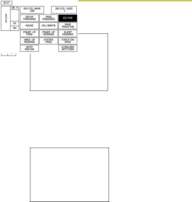
4.Press EDITOR to enable Edit mode. The EDITOR button is highlighted in the Protected Setup page when enabled, as shown in FIG. 12.
FIG. 12 Protected Setup page with the active EDITOR button
5.Press EXIT to close the Protected Setup page and return to the Setup page (now in the Edit mode).
6.Press EXIT again to return to the Main page. The EDIT button appears at the top of the page indicating that Edit mode is active.
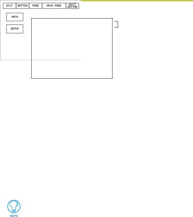
7.Press EDIT to open the Edit bar. The BUTTON and PAGE options, in the Edit bar, (FIG. 13) are used to design and modify button and page settings.
AXP-PLV PosiTrack Pilot Video Camera Controller |
11 |
|
|
|
|
Designing Touch Panel Pages
Edit bar
FIG. 13 Main page with Edit bar
Setting the Device Base
Press the DEVICE BASE option, in the Protected Setup page (FIG. 12), to assign a base (starting)
device address to the touch panel.
1.Enter the base address for the touch panel. The base address range is from 1 - 255. Standard device addresses begin at 128.
2.Press Enter to save.
Setting the Device Used
Use the DEVICE USED option in the Protected Setup page (FIG. 12) to assign an initial value for
the device address range used by the touch panel.
1.Press DEVICE USED to open the keypad and enter the panel’s device number from 1 - 4. Each device number supports up to 255 programmable channel codes. The multiple device settings allow you to create up to four unique touch panel buttons and/or pages. This value is used to determine the current device being used by the panel.
2.Enter the number of devices being used by the touch panel.
3.Press Enter to save the value.
If DEVICE USED is set to 4 and Base Device Number is 128, the Controller recognizes bus devices 128 - 131.
The panel will not allow you to enter a device number greater than the DEVICE USED without first displaying a decision box asking if you accept the new selection or not.
Adding a Page
1.Press PAGE on the Edit bar to open the PAGE menu.
2.Press ADD to open the keyboard and enter a name for the new page. Page names can be up to 20 characters.
3.Press EXIT CHANGE to save, close the keyboard, and go to the new page.
|
12 |
AXP-PLV PosiTrack Pilot Video Camera Controller |
|
|
|

Designing Touch Panel Pages
Setting the page color
1.Press EDIT to open the Edit bar on the newly created page.
2.Press PAGE on the Edit bar to open the PAGE menu.
3.Press PAGE COLOR to open the color palette.
4.Select a color from the palette; the page automatically changes to the new color.
Adding a Button
To add a button to the current page:
1.Press BUTTON on the Edit bar to open the BUTTON menu.
2.Press ADD to open the ADD BUTTON operation bar. On the LCD screen, touch and drag to create a button. The first touch point is the upper-left corner of the button.
Resizing a button
1.Press BUTTON on the Edit bar to open the BUTTON menu.
2.Press RESIZE. Then, touch any edge of the button and drag. Removing your finger from the panel saves the button dimensions.
Defining On-Screen and External Button Properties
External pushbuttons are configured with features similar to on-screen buttons. Their functionality can be set just as any other button on the touch panel.
Use the PROPERTIES option of the BUTTON menu in the Edit bar to set button borders, page flips, button colors for channel on/off conditions, channel/variable text codes, and string/macro assignments.
External button properties include only the button type, page flips, channel codes, and string/macro assignments. Although the Border and Color sections of this page appear, they are of no use to external pushbuttons since they do not appear on-screen.
Use the following steps to set button properties:
1.Press BUTTON on the Edit bar to open the BUTTON menu options.
2.Press PROPERTIES to open the PROPERTIES operation bar.
3.Press the new button to open the Button Properties page. This page lists the properties for the active button.
4.Press BUTTON TYPE; this opens the BUTTON TYPE menu.
5.Choose a button type for the selected button to open the associated Button Properties page. Each button type has its own Button Properties page with settings specific to the button type.
6.Press BORDER to open the BUTTON BORDER pages.
7.Select a border to set for the button and return to the Button Properties page. The BORDER button changes to show the selected border type.
AXP-PLV PosiTrack Pilot Video Camera Controller |
13 |
|
|
|
|
Loading...