


|
INSTALLATION |
|
|
|
INSTRUCTIONS |
|
|
|
|
T106.500 |
|
PATIENCE |
|
T106.501 |
|
TUB AND SHOWER |
T106.502 |
|
|
Thank you for selecting American Standard... |
T106.507 |
|
|
T106.508 |
|
||
the benchmark of fine quality for over 100 years. |
|
||
To ensure that your installation proceeds smoothly-please |
|
|
|
read these instructions carefully before you begin. |
|
|
|
|
|
|
Certified to comply with ANSI A112.18.1M |
RECOMMENDED TOOLS |
|
|
|
|
Phillips Screwdriver |
|
|
Plumbers’ Putty |
Teflon Tape |
Adjustable Wrench |
Channel Locks |
|
|
||
or Caulking |
Flat Blade Screwdriver |
|
|
ROUGHING-IN DIMENSIONS
•To assure proper positioning in relation to wall.
Note roughing-in dimensions.
FINISHED WALL
9-1/2"
(223 mm)
3-3/4" |
7" |
|
(97 mm) |
||
(160 mm) |
||
|
7-3/8"
(187 mm)
74" (1879 mm) FOR HEAD CLEARANCE
4-1/8"
(105 mm)
18" (457 mm)
OPTIONAL 7-5/8" (207 mm)
1-1/2" 
2-3/4"
(83 mm)
6-5/8"
(179 mm)
TOP OF TUB RIM
BOTTOM OF TUB
2" TO 3"
(51 TO 76 mm)
1/2" NPT
OPTIONAL TO FINISHED FLOOR USUALLY BETWEEN 65'' AND 78" (1651 AND 1981 mm)
8" (198 mm)
|
3-3/8" |
|
(86 mm) |
1/2" COPPER |
OUTLETS |
1/2" NPT |
|
FOR SLIP-ON |
4" |
SPOUT |
|
|
|
|
INLETS |
|
INLETS |
1/2" NOM. |
|
|
4-1/16" |
COPPER |
|
|
SWEAT |
||
SHR. 1/2" NOM. |
(103 mm) |
||
|
|
|
|
COPPER SWEAT |
|
|
|
SWEAT
INLETS
2"
4-1/16"
(103 mm)
TUB 1/2" NOM.  COPPER SWEAT


|
SWEAT |
5-7/8" |
|
|
INLETS (STOPS) |
(149 mm) |
|
|
SHR. 1/2" NOM. |
|
4-1/16" (103 mm) |
|
COPPER SWEAT |
|
|
|
TUB 1/2" NOM. |
|
|
|
COPPER SWEAT |
|
|
|
|
|
INLETS |
|
|
|
1/2" NOM. |
|
|
|
COPPER |
|
|
|
SWEAT |
|
OUTLETS |
5-7/8" |
|
|
(149 mm) |
|
|
INLETS 1/2" NPT |
1/2" NPT |
|
|
|
|
5-7/8" |
INLETS |
|
|
(149 mm) |
|
|
|
|
1/2" NPT |
3-3/8"
(86 mm)
THREADED INLETS |
THREADED INLETS (STOPS) |
Product names listed herein are trademarks of AS America, Inc. |
- 1 - |
M965819 (6/17) |
|
© AS America, Inc. 2017 |
|||
|
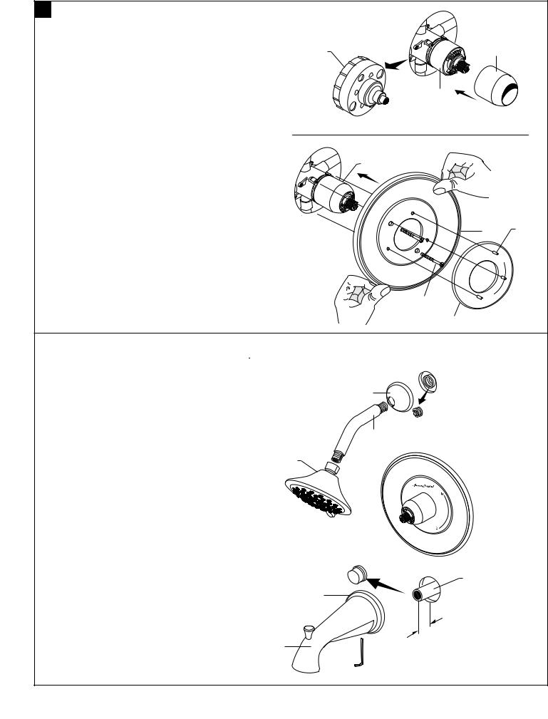
1INSTALL VALVE TRIM
•Figure 1. Remove plaster guard from valve. Push CAP (1) over VALVE CARTRIDGE (2) until seated against stop.
•Figure 2. Push ESCUTCHEON (3) onto CAP (1) and attach to valve body with LONG SCREWS (4) (cut screws if needed). Mount DECORATIVE PLATE (5) to ESCUTCHEON (3) by aligning three PINS (6) on back side of DECORATIVE PLATE (5).
PLASTER |
1 |
GUARD |
|
2
Figure 1.
1
3 6
Figure 2.
4
5
2 |
INSTALL TUB SPOUT, SHOWER HEAD, |
|
|
CAUTION |
Protect finish on SHOWER HEAD |
||
|
SHOWER ARM WITH FLANGE |
and TUB SPOUT when installing. |
|
|
|
|
H
C
•Remove pipe cap and plug from shower and tub rough piping.
•Slip DECORATIVE PLATE (5), then slip TUB SPOUT (1) onto tub nipple and tighten with 4mm Hex Wrench.
CAUTION: Protect finish on TUB SPOUT when installing.
• Install SHOWER ESCUTCHEON (2) onto SHOWER ARM (3). Apply sealant or Teflon tape to threads on 4 both ends of SHOWER ARM (3) and thread longer leg of SHOWER ARM (3) into shower elbow.
• Thread SHOWER HEAD (4) onto SHOWER ARM (3).
CAUTION: Protect finish on SHOWER HEAD and ARM when installing.
2
3
 SHR. ELBOW
 PIPE
PIPE
PLUG
PIPE
CAP
5
1
TUB FILLER
NIPPLE
. REF
1 |
-1/2" |
|
MM HEX
WRENCH
- 2 - |
M965819 (6/17) |
|
 Loading...