


 Loading...
32-5034-04
User’s Information Guide
Gas Furnaces — Non-Condensing
Fan Assisted Combustion System
Upflow / Horizontal and Downflow / Horizontal
▲! WARNING
If the information in this manual is not followed exactly, a fire or explosion may result causing property damage, personal injury or loss of life.
—Do not store or use gasoline or other flammable vapors and liquids in the vicinity of this or any other appliance.
—WHAT TO DO IF YOU SMELL GAS
•Do not try to light any appliance.
•Do not touch any electrical switch;
do not use any phone in your building.
•Immediately call your gas supplier from a neighbor’s phone. Follow the gas supplier’s instructions.
•If you cannot reach your gas supplier, call the fire department.
—DO NOT RELY ON SMELL ALONE TO DETECT LEAKS. DUE TO VARIOUS FACTORS, YOU MAY NOT BE ABLE TO SMELL FUEL GASES.
•U.L. recognized fuel gas and CO detectors are recommended in all applications, and their installation should be in accordance with the manufacturer's recommendations and/or local laws, rules, regulations, or customs.
—Installation and service must be performed by a qualified installer, service agency or the gas supplier.
▲! WARNING
DO NOT USE THIS UNIT IF ANY PART HAS BEEN UNDER WATER. IMMEDIATELY CALL A QUALIFIED SERVICE TECHNICIAN TO INSPECT THE FURNACE AND TO REPLACE ANY PART OF THE CONTROL SYSTEM AND ANY GAS CONTROL WHICH HAS BEEN UNDERWATER.
GENERAL INFORMATION
Understand the signal words DANGER, WARNING, AND CAUTION. These words are safety alert words. DANGER indicates the most serious hazards which will result in severe personal injury or death. WARNING indicates hazards which could result in personal injury or death. CAUTION is used to indicate unsafe practices which could result in minor injury or property damage.
Contents
Dangers, Warnings & Cautions |
1 |
General Information |
|
1 |
|
To Start the Furnace |
|
2 |
|
Proper Maintenance |
|
4 |
|
The Problem Solver |
|
6 |
|
Regular Dealer Maintenance |
|
7 |
|
Warranty |
|
9 |
|
|
|
|
|
IMPORTANT FACTS
The flow of combustion and ventilating air must not be obstructed from reaching the furnace. Air openings provided in the casing of the furnace must be kept free of obstructions which would restrict airflow, thereby affecting efficiency and safe operation of your furnace.
Also, air openings provided to the area in which the furnace is installed and the space around the furnace shall not be blocked or obstructed. Keep this in mind should you choose to remodel the area which contains your furnace. If additional insulation is added after the furnace is installed, the area around the furnace must be inspected to ensure it is free and clear of insulation. If this furnace is installed in an attic or other insulated space it must be kept free and clear of all insulating materials as some insulating materials are combustible.
Furnaces must have air for proper performance. There must be a free flow of fresh air sufficient for efficient combustion and safe ventilation of your furnace.
The combustion air for your furnace must be fresh uncontaminated air. Paints, varnishes, laundry bleaches, detergents, many household cleaners, water softening salts, adhesives, and all such products release fumes containing compounds which could lead to early heat exchanger and vent system deterioration. Do not store these types of products near your furnace.
Never store gasoline, combustible materials, or other flammable liquids or vapors near your furnace.
Carbon monoxide, fire or smoke can cause serious bodily injury, death, and/or property damage.

User’s Information
A variety of potential sources of carbon monoxide can be found in a building or dwelling such as gas-fired clothes dryers, gas cooking stoves, water heaters, furnaces and fireplaces. The U.S. Consumer Product Safety Commission recommends that users of gas-burning appliances install carbon monoxide detectors as well as fire and smoke detectors, listed by a nationally recognized agency (e.g. Underwriters Laboratories or International Approval Services), to help alert dwelling occupants of the presence of fire, smoke or unsafe levels of carbon monoxide.
NOTE:
The manufacturer of your furnace does not test any detectors and makes no representations regarding any brand or type of detector.
▲! WARNING
BODILY INJURY CAN RESULT FROM HIGH VOLTAGE ELECTRICAL COMPONENTS, FAST MOVING FANS, AND COMBUSTIBLE GAS. FOR PROTECTION FROM THESE INHERENT HAZARDS DURING INSTALLATION AND SERVICING, THE ELECTRICAL SUPPLY MUST BE DISCONNECTED AND THE MAIN GAS VALVE MUST BE TURNED OFF.
Installing and servicing heating equipment can be hazardous due to gas and electrical components. Only trained and qualified personnel should install, repair or service heating equipment.
Untrained personnel can perform basic maintenance functions such as cleaning and replacing filters. All other operations must be performed by trained service personnel.
Parts and controls of this furnace are unique. Should service or modification be required, be sure your servicer uses only factory authorized parts, kits, or accessories for this furnace.
If you experience a problem with the operation of your furnace, check the “Problem Solver” section of this manual before you call for a possibly unneeded service call.
▲! WARNING
Improper installation, adjustment, alteration, service or maintenance can cause injury or property damage. Refer to the installation instructions provided with the furnace and this manual. For assistance or additional information consult a qualified installer, service agency or the gas supplier.
To Start the Furnace
Lighting instructions.
Your furnace does not use a continuously burning pilot flame. Therefore, manually lighting your furnace is not required. Your furnace is equipped with an automatic ignition system. It uses a hot surface ignition device that automatically lights the burners each time the thermostat signals the furnace to start.
▲! WARNING
Do not attempt to manually light the furnace.
1.Please read all safety information in this book before operating furnace.
2.Set thermostat to lowest setting. Turn off all electric power to furnace.
3.Remove the furnace front panel to gain access to the main gas valve.
4.Turn gas cock knob clockwise or the toggle switch located on the main gas valve inside the unit to “OFF” position (see illustration on next page). If external gas cock is used, turn to “OFF” position (see illustration on next page). Allow 5 minutes for any gas within the unit to escape. LP gas being heavier than air may require forced ventilation. If you smell gas STOP! Follow the “What To Do If You Smell Gas” instructions on the front cover of this book. If you don’t smell gas, go to next step.
5.Turn gas cock knob counterclockwise or the toggle switch to “ON” marker (see illustration on next page).
6.Replace the furnace front access panel.
7.Turn on main electrical supply and set thermostat to desired setting. Combustion blower will start and ignition device will start to heat up. After approximately 15 seconds main gas valve will open and burners will ignite.
8.When thermostat is satisfied, main burners will extinguish.
9.If main burners fail to ignite, lower thermostat setting or disconnect electrical supply, wait 5 minutes, raise thermostat setting above indicated temperature.
10.If furnace will not light, turn “OFF” all gas and electricity to unit and call servicer or gas supplier.
For complete shutdown.
Turn gas cock knob on main gas valve to “OFF” position. Disconnect electrical supply to unit.
▲! CAUTION
If this is done during the cold weather months, provisions must be taken to prevent freeze-up of all water pipes and water receptacles.
Whenever your house is to be vacant, arrange to have someone inspect your house for proper temperature. If your furnace should fail to operate, damage could result, such as frozen water pipes.
Flame Roll-out Device.
All models are equipped with a fusible link located near the burners. In case of flame roll-out, the link will open (melt) and cause the circuit to open which shuts off all flow of gas.
© 2002 American Standard Inc. All Rights Reserved |
32-5034-04 |

User’s Information
Outlet Pressure Boss
Regulator
Adjust
Inlet Pressure
Boss (opt.)
Your furnace may have a “Knob Switch” or a “Toggle Switch” to turn the gas
ON or OFF.
SWITCH TOGGLES
“ON” OR “OFF”
On/Off Switch
NOTE THE LOCATION OF THE MANUAL MAIN GAS SHUT-OFF VALVE FOR YOUR FURNACE.
Have your installer or servicer show you the location if you have any questions.
UPFLOW FURNACE Manual Main Gas Shut-off Valve May Be Located on the Left or Right Side
GROUND
UNION JOINT
HORIZONTAL FURNACE Manual Main Gas Shut-off Valve May Be Located on the Top or Bottom Side
TOP VIEW OF RIGHT SIDE PIPING
32-5034-04 |
3 |
User’s Information
Proper Maintenance
Reduces Energy Use
A clean filter saves money.
When the furnace circulates and filters the air in your home, dust and dirt particles build up on the filter. Excessive accumulation can block the airflow, forcing the unit to work harder to maintain desired temperatures.
And the harder your unit has to work, the more energy it uses. So you pay more any time your system is running with a dirty filter.
▲! CAUTION
Never operate your unit for either heating or cooling with filters removed.
Help ensure top efficiency by cleaning the filter once a month. If you have an upflow furnace, you can wash or change the filter once a month. Clean it twice a month during seasons when the unit runs more often.
Your furnace came from the factory with a cleanable filter. You can clean the filter with a vacuum, OR you can wash it with a household detergent. Good quality, high velocity filters may be used for replacements in upflow furnaces.
With the new patented filter rack on the upflow models, all cleaning or replacing of filters is quick and easy. Clean filters guarantee optimum performance of your system.
FACTORY SUPPLIED UPFLOW FURNACE
RETURN AIR FILTERS
UPFLOW FURNACE RETURN AIR FILTERS
CABINET |
QTY* |
CABINET |
CABINET |
|
WIDTH |
BOTTOM FILTER |
SIDE FILTER |
||
|
||||
|
|
|
|
|
14-1/2" |
1 |
14" X 25" X 1" |
17-1/2" X 25" X 1" |
|
|
|
|
|
|
17-1/2" |
1 |
17" X 25" X 1" |
17-1/2" X 25" X 1" |
|
|
|
|
|
|
21" |
1 |
20" X 25" X 1" |
17-1/2" X 25" X 1" |
|
|
|
|
|
|
24-1/2" |
1 |
24" X 25" X 1" |
17-1/2" X 25" X 1" |
|
|
|
|
|
*NOTE - On 5 ton airflow models, if the airflow requirement exceeds 1800 CFM, these models will require filters on both sides; OR 1 side and the bottom; OR just the bottom.
Replacing your filter.
When replacing your furnace filters, use a high velocity type filter. On upflow furnaces, standard size 1" thick high velocity filters will fit into the patented filter rack which will automatically adjust in width to fit. Filters are available from your dealer.
How to remove your filter.
The upflow furnace blower door has a hinge at the bottom which allows the door to tilt forward for filter servicing or replacement without the door being removed. The furnace filter in the bottom or side configuration can be removed by simply turning the two latches on the blower door 1/4 turn and tilting the door forward.
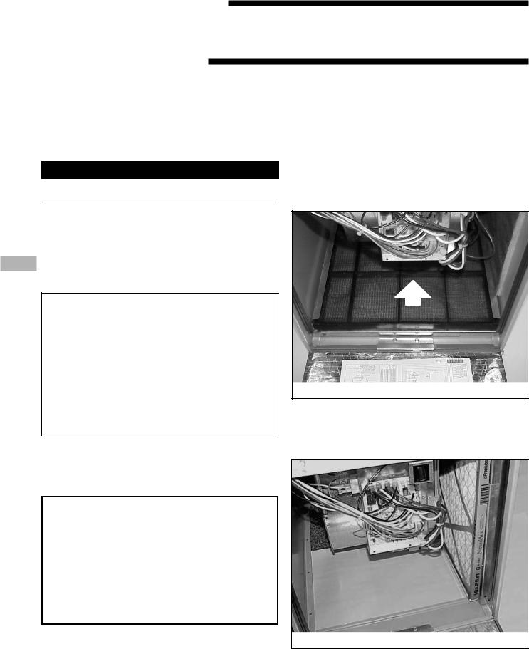
Airflow
Blower Door Hinge and Bottom Filter Rack Installation
The blower door may be removed if necessary by tilting the door outward 2 to 3 inches, then pulling up. The door will slide out of the hinge for removal. For replacement, simply insert the blower door bottom into the space between the furnace base front and the hinge, then tilt inward and latch.
 Airflow
Typical Upflow Right Side Return Filter Installation
4 |
32-5034-04 |
Loading...