


|
Installation |
|
ENFIELD |
Instructions |
|
2373.401 |
||
BIDET FITTING |
||
2373.421 |
||
and VACUUM BREAKER |
||
|
||
with EverClean™ Finish |
|
Congratulations on purchasing your American Standard faucet with EverClean finish found only on American Standard faucets.
EverClean Finish
•One wipe effortlessly removes spots
•Eliminates the need for cleaners and scrubbing
•Permanent surface protectant remains beautiful for the life of the faucet
•EverClean™ available on: Polished Chrome, Satin Nickel,
Stainless Steel, Polished Brass (or any combination of these finishes)
Certified to comply with ASME A112.18.1M U.S. Patent No. 5,819,789
. 3&7
To ensure that your installation proceeds smoothly-please read these instructions carefully before you begin.
Required Tools
*Wrench
Flat Blade Screwdriver
Adjustable Wrench |
Channel Locks |
5VCJOH $VUUFS |
|
Phillips Screwdriver |
*Supplied with Fitting |
|
Roughing-in Dimensions
FINISHED
WALL
BIDET OUTLINE |
TRANSFER VALVE |
|
(FOR FLUSHING |
||
IS SYMBOLIC |
RIM OR SPRAY) |
|
DOUCHE |
7/8 DIA. |
|
SPRAY |
||
|
ADJ. 1-1/4 |
2-1/8 |
|
TO 2-1/4 |
DIA. |
|
1-3/8 |
|
3-7/8 |
DIA. |
|
5-1/2
 1-1/4 O.D. TAILPIECE
DIVERTER AND
8 TO 12 VACUUM BREAKER ASSEMBLY
(C)(H)
|
2-1/4 |
|
DIA. |
1-3/16 |
|
DIA. |
4-1/4 |
|
|
1-1/4 |
|
MAX. |
FOR GROUND JOINT |
|
|
|
CONNECTION OR 1/2" |
|
O.D. SLIP (INLETS) |
FINISHED |
REAR VIEW WITH |
FLOOR |
WALL REMOVED |
|
MOUNTING BIDET FAUCET |
||
|
|
Turn off hot and cold water |
|
|
CAUTION |
||
|
|
|
supplies before beginning. |
|
|
|
|
Place MOUNTING NUTS (1) onto the VALVE BODIES
(2) and insert VALVE BODIES (2) through outside holes, from underside of the BIDET LEDGE. Drop the RUBBER RING (3) over the VALVE BODIES (2) and thread DECK ADAPTER (4) onto VALVE BODIE (2) until it locks against the internal stop.
Tighten the MOUNTING NUT (1) to secure the VALVE BODIES (2).
Remove MOUNTING NUT (9), FRICTION RING (10) and UPPER GASKET (7) from TRANSFER VALVE (8) and insert TRANSFER VALVE (8) into the center forward hole of BIDET.
Replace UPPER GASKET (7) and FRICTION RING (10). Position the side threaded outlet rearward and secure MOUNTING NUT (9). Thread ESCUTCHEON (5) onto TRANSFER VALVE (8) until it seats against the BIDET LEDGE.
5 |
9 |
|
|
|
10 |
4 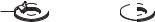


 3
3 


BIDET
LEDGE
2
HOT  COLD
COLD
1 |
7 |
|
|
|
8 |
DRAIN INSTALLATION
Assemble O-RING (1), WASHER (2), PIVOT ROD (3) and NUT (4) to DRAIN BODY (5). Concave side of cup WASHER (2) is toward ball.
Thread LOCKNUT (6), WASHER (7) and
GASKET (8) onto DRAIN BODY (5).
Apply a bead of PUTTY to underside of FLANGE (9).
Feed DRAIN BODY (5) up through BIDET |
|
|
and thread FLANGE (9) fully onto |
|
|
BODY (5). |
STOPPER |
|
Tighten LOCKNUT (6) firmly, keeping the |
||
PIVOT ROD (3) pointed towards the back |
|
|
of the BIDET. |
9 |
|
Push DRAIN ESCUTCHEON (10) onto |
|
|
TAILPIECE (11). |
PUTTY |
|
8 |
BIDET |
|
CLIP |
||
7 |
4 |
|
2 |
||
|
3
6
1
5
11
10
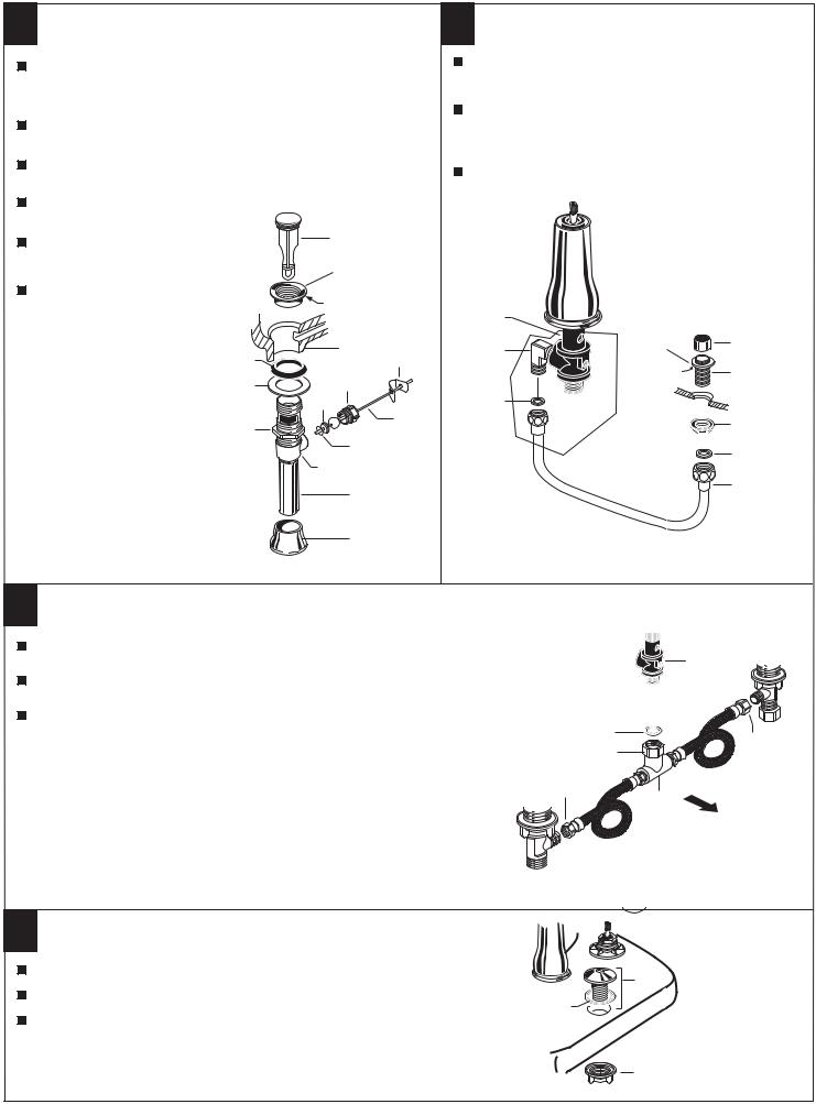
SPRAY INSTALLATION
Assemble SPRAY BODY (1) to BIDET. Using putty, seal underside of SPRAY BODY FLANGE (2) and secure with NUT (3).
Screw SPRAY HOSE (4) with SEAL WASHER (5) to SPRAY BODY (1). Connect other end of HOSE (4) with SEAL WASHER (6) to side outlet NIPPLE (7) of the TRANSFER VALVE (8).
Screw SPRAY CAP (9) onto SPRAY BODY (1).
8 |
|
|
7 |
2 |
9 |
|
|
|
|
PUTTY |
1 |
6 |
|
|
|
|
3 |
|
|
5 |
|
|
4 |
TEE AND HOSE CONNECTION
Insert SEAL (1) into ADAPTER (2) and tighten ADAPTER (2) to bottom of TRANSFER VALVE (3).
Install SEAL (4) into coupling nut of TEE (5) and tighten connection to ADAPTER (2)
Connect HOSE COUPLING NUTS (6) to Hot and Cold valve bodies and securely tighten.
Cold
3
 1 2
1 2 
4
6
COUPLING
NUT
Hot 6
5
Front
LIFT ROD GUIDE INSTALLATION
Unscrew LIFT ROD NUT (1) from LIFT ROD GUIDE (2).
2
Make sure SEAL (3) is seated into ESCUTCHEON of LIFT ROD GUIDE (2).
3
Drop LIFT ROD GUIDE (2) into rear hole of bidet and from below secure with ROD GUIDE NUT (1).
1
. 3&7
 Loading...