


 Loading...
www.mgeups.com
AmpMeter PDU
Installation and user manual
R
R
E
T
N
I
N
U
E
H
T
U
P
T
I
B
|
|
O |
V |
I |
|
R |
|
||
|
|
|
||
P |
|
|
|
|
|
|
|
|
R
E
|
W |
P |
O |
|
L |
E |
|
D
E
R
Instructions
This symbol is intended to alert the user to the presence of important operating and maintenance (servicing) instructions in the literature accompanying the appliance.
Dangerous Voltage
This symbol is intended to alert the user to the presence of un-insulated dangerous voltage within the product’s enclosure that may be of sufficient magnitude to constitute a risk of electric shock to persons.
Protective Grounding Terminal
This symbol indicates a terminal that must be connected to earth ground prior to making any other connections to the equipment.
Life-Support Policy
As a general policy, MGE UPS SYSTEMS does not recommend the use of any of its products in the following situations:
•life-support applications where failure or malfunction of the MGE UPS SYSTEMS product can be reasonably expected to cause failure of the life-support device or to significantly affect its safety or effectiveness.
•direct patient care.
MGE UPS SYSTEMS will not knowingly sell its products for use in such applications unless it receives in writing assurances satisfactory to MGE UPS SYSTEMS that:
•the risks of injury or damage have been minimized,
•the customer assumes all such risks, and
•the liability of MGE UPS SYSTEMS is adequately protected under the circumstances.
The term life-support device includes but is not limited to neonatal oxygen analyzers, nerve stimulators (whether used for anesthesia, pain relief or other purposes), auto-transfusion devices, blood pumps, defibrillators, arrhythmia detectors and alarms, pacemakers, hemodialysis systems, peritoneal dialysis systems, neonatal ventilator incubators, ventilators (for adults or infants), anesthesia ventilators, infusion pumps, and any other devices designated as “critical” by the U.S. FDA.
Compliance
Units have been safety tested/certified to the following standards: USA and Canada to
UL 60950-1:2003 and CAN/CSA 22.2 No. 60950-1-03, European Union to EN60950-1:2001
USA Notification
Warning: Changes or modifications to these units not expressly approved by the party responsible for compliance could void the user’s authority to operate the equipment under FCC rules.
Note: This equipment has been tested and found to comply with the limits for a Class A digital device, pursuant to Part 15 of the FCC Rules. These limits are designed to provide reasonable protection against harmful interference when the equipment is operated in a commercial environment. This equipment generates, uses and can radiate radio frequency energy and, if not installed and used in accordance with the instruction manual, may cause harmful interference to radio communications. Operation of this equipment is a residential area is likely to cause harmful interference in which case the user will be required to correct the interference at his own expense.
Canadian Notification
This digital apparatus does not exceed the Class A limits for radio noise emissions from digital apparatus set out in the Radio Interference Regulations of the Canadian Department of Communications.
Le présent appareil numérique n’émet pas de bruits radioélectriques dépassant les limites applicables aux appareils numériques de la classe A prescrites dans le Règlement sur le brouillage radioélectrique édicté par le Ministère des Communications du Canada.
Japanese Notification
スA

|
Contents |
GETTING STARTED |
4 |
Quick Start Guide .......................................................................................................................... |
4 |
INSTALLATION |
5 |
Standard Accessories ................................................................................................................... |
5 |
Additional Required Items ............................................................................................................ |
5 |
Equipment Overview ..................................................................................................................... |
5 |
Safety Precautions ........................................................................................................................ |
6 |
Installing the Power Input Retention Bracket ............................................................................ |
6 |
Mounting ......................................................................................................................................... |
7 |
Connecting to the Power Source................................................................................................. |
7 |
Connecting Devices ...................................................................................................................... |
8 |
Connecting the Sensors ............................................................................................................... |
8 |
Connecting to the Unit (Remote Monitoring Units Only).......................................................... |
8 |
OPERATIONS |
10 |
Interfaces ...................................................................................................................................... |
10 |
HTML Interface ............................................................................................................................ |
11 |
Command Line Interface ............................................................................................................ |
18 |
ADVANCED OPERATIONS |
33 |
SSL ................................................................................................................................................ |
34 |
SSH ............................................................................................................................................... |
35 |
SNMP ............................................................................................................................................ |
36 |
APPENDICES |
45 |
Resetting to Factory Defaults .................................................................................................... |
46 |
Uploading Firmware .................................................................................................................... |
46 |
Technical Specifications ............................................................................................................. |
47 |

1. Getting Started
Quick Start Guide
The following instructions will help you quickly install and configure your AmpMeter PDU for use on your network. For detailed information on each step, go to the page number listed to the right.
For your network security, MGE UPS SYSTEMS strongly recommends the removal of the predefined user account prior to attachment to your network.
1. |
Mount the AmpMeter PDU..................................................................................................................... |
6 |
|
2. |
Connect to the power source................................................................................................................. |
3 |
|
3. |
Connect the devices to the AmpMeter PDU .......................................................................................... |
7 |
|
4. |
Connect to the AmpMeter PDU ............................................................................................................. |
8 |
|
5. |
Configure the AmpMeter PDU (remote monitoring units only) .............................................................. |
8 |
|
|
• |
Login as the predefined Administrator (admn/admn) .................................................................. |
10 |
|
• |
Create new administrative user account ............................................................................... |
14, 22 |
|
• |
Configure location and tower names ..................................................................................... |
12, 26 |
|
• |
Remove the predefined Administrator ................................................................................... |
14, 22 |
6.Connect the AmpMeter PDU to the network
Page 4 - 301-0399-3 Rev A.

2. Installation
Before installation, refer to the following lists to ensure that you have all the items shipped with the unit as well as all other required items.
Standard Accessories
•Mounting hardware - two removable flanges with four M4 screws and two mounting L-brackets with nut plates and four sets of screws and washers.
For remote monitoring units only:
•RJ45 to RJ45 crossover cable
•RJ45 to DB9F serial port adapter (for connection to standard DB9M DTE serial port)
Additional Required Items
•Phillip screwdriver
•Screws, washers and nuts to attach the unit to your rack
Equipment Overview
•The Input Current LED(s) displays the current load for each infeed or electrical phase per infeed.
•Each Branch Circuit / electrical phase is color-coded for easy identification.
•The power inlet/cord(s) connects the PDU to the electrical power source.
•Two RJ45 connectors for Serial (RS-232) and Ethernet connection (remote monitoring units only).
•Two mini RJ11 connectors for Temperature/Humidity sensors (remote monitoring units only).
1Power Input
2Input Current LED
3Ethernet / RS232 Ports
4Temperature / Humidity Ports
M G
UPSSYSTEEMS www.mg SmarteCups.com
DU
3
I I |
I |
4 |
S 2ensor
1
A
1 
2 
3
1
2
1 3
2
3
2
1 |
1 |
B |
|
2
1
Input
Current
2
Branch 1 |
|
|
|
isco |
nnect |
|
|
|
|
ly |
|||
|
|
|
|
ys d |
upp |
|
|
|
Alwapowerspening |
||||
|
|
|
the |
re o |
hock. |
|
|
|
cord |
befo |
al s |
|
|
1) |
|
lectric |
|
|
||
|
av |
oid e |
|
|
||
h |
to |
|
|
|
|
|
nc |
|
|
|
|
|
|
ra |
|
|
|
|
|
|
(B |
1F |
|
|
|
|
|
F1 |
|
|
|
|
|
|
|
|
|
|
|
|
cs |
|
|
|
|
éviter |
les cho hez |
|
|
|
|
|
ébranc |
||
|
Afin d'ues, d |
lectrique |
||||
2) |
électriqcable dé'ouvrir. |
|||||
h |
|
le |
ant |
|
|
|
nc |
|
|
av |
|
|
|
ra |
|
|
|
|
|
|
(B |
|
|
|
|
|
|
F2 |
|
|
|
|
|
|
F
2 deIemlenamkzuAterusiruskvfcNumehperaepmtnzceehlleSinedictneuvhonnular.gmgN CAUnTt fIirOe
repalancdTeotwyppritehevefsuasmeeonslyize
Branch 2
M G
UPS E
SYSTEMS
www.m
AmpMgeups.com eter PDU
1
Figure 0.1 AmpMeter PDU Views
301-0399-3 Rev A. - Page 5
2. Installation
Safety Precautions
This section contains important safety and regulatory information that should be reviewed before installation and use. For input and output current ratings, see Power Ratings in Technical Specifications.
Only for installation and use in a Restricted Access Location in accordance with the following installation and use instructions.
Seulement pour l’installation et l’utilisation dans une Zone Interdite conformément aux installations et l’utilisation des indications suivants.
Nur zur Installation und Verwendung in einem Sicherheitsbereich gemäß den folgenden Installationsund Verwendungsanleitungen.
This equipment is designed to be |
Cet équipement est conçu à être |
Diese Ausrüstung ist zur Installation in |
installed on a dedicated circuit. |
installé sur un circuit spécialisé. |
einem festen Stromkreis vorgesehen. |
Dedicated branch circuit must have circuit breaker or fuse protection; 3- phase/multi-pole dedicated branch circuits must have circuit breaker or fuse protection for each phase/pole located together. PDUs have been designed without a master circuit breaker or fuse to avoid becoming a single point of failure. It is the customer’s responsibility to provide adequate protection for the dedicated branch power circuit. Protection should not exceed the Total Input Rating of the PDU and must meet all applicable local, state and federal codes and regulations.
Le circuit de dérivation spécialisé doit être équipé de disjoncteurs ou de fusibles ;
Lorsqu'ils sont triphasés ou multipolaires, ils doivent être équipés de disjoncteurs ou de fusibles sur chaque phase ou pôle. Les PDU ont été conçus sans disjoncteur ou fusible principal afin de ne pas constituer le seul point de rupture. Le client est seul responsable de la protection des circuits électriques de dérivation spécialisés. Cette protection ne doit pas excéder la consommation totale en entrée du PDU et doit être conforme aux normes et à la réglementation locales, d'état et fédérales.
Der als Standleitung verwendete Zweigstromkreis muss mit einem Überlastschalter bzw. einer Sicherung ausgestattet sein; bei StandleitungsZweigstromkreisen mit 3 Phasen/mehreren Polen müssen zusammengehörige Phasen/Pole individuell durch einen Überlastschalter bzw. eine Sicherung geschützt sein. In PDUs ist kein Haupt-Überlastschalter bzw. keine Hauptsicherung installiert. Dadurch wird ausgeschlossen, dass die PDU als alleinige Schwachstelle in Frage kommt. Es liegt in der Verantwortung des Kunden, den als Standleitung verwendeten Zweigstromkreis durch entsprechende Schutzmaßnahmen vor Überlastung zu schützen. Der Wert für den Überlastschutz darf nicht über dem Wert für die Eingangsstromstärke der PDU liegen und muss geltenden örtlichen und staatlichen Bestimmungen entsprechen.
The plug on the power supply cord shall |
La prise sur le cordon d’alimentation |
Der Stecker des Netzkabels muss in der |
be installed near the equipment and |
sera installée près de l’équipement et |
Nähe der Ausrüstung installiert werden |
shall be easily accessible. |
sera facilement disponible. |
und leicht zugänglich sein. |
Always disconnect the power supply |
Toujours déconnecter le cordon |
Ziehen Sie vor dem Öffnen immer das |
cord before opening to avoid electrical |
d’alimentation avant d’ouvrir pour |
Netzkabel heraus, um die Gefahr eines |
shock. |
éviter un choque électrique. |
elektrischen Schlags zu vermeiden. |
WARNING! High leakage current! |
ATTENTION ! Haut fuite très |
ACHTUNG! Hoher Ableitstrom! Ein |
Earth connection is essential before |
possible ! Une connection de masse |
Erdungsanschluss ist vor dem |
connecting supply! |
est essentielle avant de connecter |
Einschalten der Stromzufuhr |
|
l’alimentation ! |
erforderlich! |
|
|
|
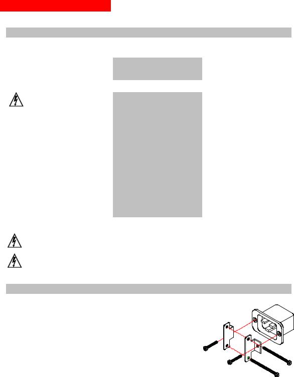
Installing the Power Input Retention Bracket
For Switched PDUs with a total maximum output <30A, it may be necessary to install the power input retention bracket prior to mounting the Switched PDU within the rack.
To install the power input retention bracket:
1.Remove the two screws attaching the IEC 60320 C19 inlet to the
enclosure.
2.Assemble and attach the retention bracket to the enclosure as
shown.
Figure 2. Retention Bracket assembly
Page 6 - 301-0399-3 Rev A.
2. Installation
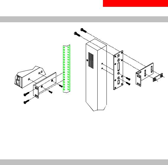
Mounting
Figure 3. Mounting
Horizontal/Rack
1.Select the appropriate bracket mounting points for proper mounting depth within the rack.
2.Attach the brackets to these mounting points with two screws for each bracket.
3.Install the enclosure into your rack, using the slots in each bracket. The slots allow about ¼ inch of horizontal adaptability to align with the mounting holes of your rack.
Vertical/Tower
1.Attach the removable flanges to the mount points on the rear of the enclosure using M4 screws.
2.Attach the mounting L-brackets to the flanges with the supplied screws, washers and nut plates. The slots allow about 1½ inches of vertical adaptability.
3.Attach the top and bottom brackets to your rack.
Connecting to the Power Source
To attach a power cord to the unit:
1.Plug the female end of the power cord firmly into its connector at the base.
2.Use a screwdriver to tighten the two screws on the retention bracket.
To connect to the power source:
Plug the male end of the power cord into the AC power source.
301-0399-3 Rev A. - Page 7
2. Installation
Connecting Devices
To avoid the possibility of noise due to arcing:
1.Keep the device’s on/off switch in the off position until after it is plugged into the outlet.
2.Connect devices to the outlets.
On 230V units, install a retention clip for each outlet; Pull the prongs out slightly and insert them into holes on the sides, then insert the device’s power cord and snap the clip over the cord.
NOTE:
1.MGE UPS SYSTEMS recommends even distribution of attached devices across the all available outlets to avoid exceeding the outlet, quad or octet ratings limitations. See Power Ratings in Technical Specifications for more information.
2.The outlet retention clips provided with 230V units are designed for use with MGE UPS SYSTEMS’s IEC 60320/C13 to IEC 60320/C14 cable and may not properly fit 3rd party cables.
Always disconnect the power supply cord before opening to avoid electrical shock.
Afin d’éviter les chocs électriques, débranchez le cable électrique avant d’ouvrir.
Immer Netzleitung auskuppeln vor den Aufmachen um elektrischen Schlag zu vermeiden.
Connecting the Sensors
The AmpMeter PDU may be equipped with two mini RJ11 T/H ports for attachment of the included Temperature/Humidity sensor. Attach the mini RJ11 plug of the sensor(s) to the appropriate T/H port if applicable.
Connecting to the Unit (Remote Monitoring Units Only)
Serial (RS232) port
AmpMeter PDU models may be equipped with an RJ45 Serial RS-232 port for attachment to a PC or networked terminal server using the supplied RJ45 to RJ45 crossover cable and RJ45 to DB9F serial port adapter as required. See Data Connections in Technical Specifications for more information on the Serial RS-232 port.
Ethernet port
AmpMeter PDU models may be equipped with an RJ45 10/100Base-T Ethernet port for attachment to an existing network. This connection allows access via Telnet, Secure Shell (SSH) or a common web browser.
The unit configured with the following network defaults to allow unit configuration out-of-the-box through either Telnet/SSH or via a web browser:
• |
IP address: |
192.168.1.254 |
• |
Subnet Mask: |
255.255.255.0 |
• |
Gateway: |
192.168.1.1 |
The local PC network connection must be configured as noted below:
NOTE: Contact your system administrator for instructions in reconfiguring the network connection. Reconfiguration of your network connection may require a restart to take effect.
• |
IP address: |
192.168.1.x (where x is 2-253) |
• |
Subnet Mask: |
255.255.255.0 |
Page 8 - 301-0399-3 Rev A.

|
3. Operations |
INTERFACES |
10 |
Usernames and Passwords |
10 |
HTML INTERFACE |
11 |
Logging In |
11 |
Environmental Monitoring |
12 |
Input Load ........................................................................................................................... |
12 |
Sensors ............................................................................................................................... |
12 |
Configuration |
12 |
System................................................................................................................................. |
12 |
Network ............................................................................................................................... |
13 |
Telnet/SSH.......................................................................................................................... |
13 |
HTTP/SSL ........................................................................................................................... |
13 |
Serial Ports ......................................................................................................................... |
14 |
Users.................................................................................................................................... |
14 |
FTP ...................................................................................................................................... |
15 |
SNTP ................................................................................................................................... |
16 |
SNMP .................................................................................................................................. |
16 |
Tools |
17 |
Restart ................................................................................................................................. |
17 |
COMMAND LINE INTERFACE |
18 |
Logging In |
18 |
Operations Commands |
20 |
Administration Commands |
22 |
User Administration ........................................................................................................... |
22 |
Serial Port Administration ................................................................................................. |
25 |
System Administration ...................................................................................................... |
26 |
TCP/IP Administration....................................................................................................... |
28 |
HTTP Administration ......................................................................................................... |
30 |
Telnet Administration......................................................................................................... |
30 |
FTP Administration ............................................................................................................ |
31 |
SNTP Administration ......................................................................................................... |
32 |
301-0399-3 Rev A. - Page 9

3. Operations
This chapter contains information on commands and abilities available only in models equipped for remote monitoring.
Interfaces
The AmpMeter PDU has two interfaces: the HTML interface accessed via the HTTP enabled Ethernet connections and the command line for serial and Telnet connections.
Usernames and Passwords
The AmpMeter PDU has one predefined administrative user account (username/password: admn/admn) and supports a maximum of 128 defined user accounts
NOTE: For security, MGE UPS SYSTEMS recommends removal of the predefined administrative user account after a new account with administrative rights has been created.
Only an administrative-level user may perform operations such as creating/removing user accounts and command privileges, changing passwords and displaying outlet and user information. An administrator may also view the status of and control power to all outlets.
The administrator may create additional user accounts and then grant these users the right to view the status of and control power to specific outlets, groups and ports.
Usernames may contain from 1 to 16 characters and are not case sensitive; spaces are not allowed. Passwords may contain up to 16 characters, and are case sensitive.
Page 10 - 301-0399-3 Rev A.
3. Operations
HTML Interface
The HTML interface is constructed of three major components: the System Location bar, the User/Navigation bar and the Control Screen. The System Location bar displays the AmpMeter PDU’s location and IP address as well as the current Control Screen title. The User/Navigation bar displays the current user and privilege level and provides access to all HTML pages. And the Control Screen is used to display current data and allow changes to outlet states or system configuration.
The following sections describe each interface section/page and their use.
Figure 4. Example HTML page
Logging In
Logging in through HTML via a web browser requires directing a web client to the configured IP address of the unit.
To log in by HTML:
1.In the login window, enter a valid username and password and press OK. If you enter an invalid username or password, you will be prompted again.
You are given three attempts to enter a valid username and password combination. If all three fail, the session ends and a protected page will be displayed.
301-0399-3 Rev A. - Page 11

3. Operations
Environmental Monitoring
The Environmental Monitoring section offers access to the Input Load page. This section is available to administrative level users and users with Environmental Monitoring view rights.
Input Load
The Input Load page displays the AmpMeter PDU (s) absolute and descriptive name and the cumulative input load in amperes of all devices attached to the AmpMeter PDU at the time the page was loaded. This page will refresh automatically every 10 seconds.
Sensors
The Sensors page displays:
•Temperature/humidity sensor’s absolute and descriptive names
•Temperature/humidity sensor readings in degrees Celsius and percent relative humidity
Configuration
The Configuration section offers access to all unit configuration options including Network, Telnet/HTTP, Serial Ports, Outlets, Groups, Users, FTP, Proxy/SNTP and SNMP. This section is available to administrative level users only.
System
The System configuration page is used for reference of system information such as Ethernet NIC Serial Number, Ethernet MAC address and system firmware and hardware revisions as well as assignment and maintenance of the system location and tower descriptive names.
For description names, up to 24 alphanumeric and other typeable characters (ASCII 33 to 126 decimal – spaces and colon characters are not allowed) are allowed.
NOTE: Spaces may be used for the location description only.
Creating a descriptive system location name:
Enter a descriptive name and press Apply.
Creating a descriptive unit name:
Click on the Tower Names link.
On the subsequent Tower Names page, enter a descriptive name and press Apply.
Creating descriptive input feed names:
Click on the Input Feed Names link.
On the subsequent Input Feed Names page, enter a descriptive name and press Apply.
Creating a descriptive Pass through port name:
Click on the Serial Port Names link which will open the Serial Ports configuration page. See Creating a descriptive serial port name: on page 14 for additional information on creating descriptive Serial port names.
Creating a descriptive Environmental Monitor name:
Click on the Environmental Monitor Names link.
On the subsequent Environmental Monitor Names page, enter a descriptive name and press Apply.
Creating descriptive sensor names:
Click on the Sensor Names link.
On the subsequent Sensor Names page, enter a descriptive name and press Apply.
Page 12 - 301-0399-3 Rev A.

3. Operations
Network
The Network configuration page is used for maintenance of the network interface. From this page an administrator may configure the IP address, subnet mask and gateway address as well as view the link status, speed and duplex value.
The AmpMeter PDU is configured with the following network defaults to allow unit configuration out-of-the-box through either Telnet or HTML:
• |
IP address: |
192.168.1.254 |
• |
Subnet Mask: |
255.255.255.0 |
• |
Gateway: |
192.168.1.1 |
The initial local PC network connection must be configured as noted below:
NOTE: Contact your system administrator for instructions in reconfiguring the network connection. Reconfiguration of your network connection may require a restart to take effect.
• |
IP address: |
192.168.1.x (where x is 2-253) |
• |
Subnet Mask: |
255.255.255.0 |
NOTE: The unit must be restarted after network configuration changes.
See Performing a warm boot: on page 17.
Setting the IP address, subnet mask or gateway:
In the appropriate field, enter the IP address, subnet mask or gateway address and press Apply.
Telnet/SSH
The Telnet/SSH configuration page used to enable or disable Telnet and SSH support and configure the port number that the Telnet or SSH server watches. For more information on SSH see page 35.
Enabling or disabling Telnet or SSH support:
Select Enabled or Disabled from the appropriate Server drop-down menu and press Apply.
Changing the Telnet or SSH server port number:
In the appropriate Port field, enter the port number and press Apply.
HTTP/SSL
The HTTP/SSL configuration page used to enable or disable HTTP and SSL support, configure the port number that the HTTP server watches and responds to, selection of the method of authentication used and SSL access level. For more information on SSL see page 34 in.
Enabling or disabling HTTP or SSL support:
Select Enabled or Disabled from the appropriate Server drop-down menu and press Apply.
Changing the HTTP server port number:
In the HTTP Port field, enter the port number and press Apply.
301-0399-3 Rev A. - Page 13

3. Operations
Setting the HTTP authentication method:
The AmpMeter PDU HTTP server supports two authentication methods for security and validation of the username-password – Basic and MD5 digest.
The Basic method utilizes Base64 encoding to encode and deliver the username-password over the network to the HTTP server for decoding and authentication. This basic method is supported by all web browsers and offers a minimum level of security.
NOTE: The Base64 algorithm is widely-known and susceptible to packet-sniffer attack for acquisition of the encoded username-password string.
The MD5 digest method provides stronger protection utilizing one-way encoded hash numbers, never placing the username-password on the network. Instead, the sending browser creates a challenge code based on the hash algorithm, provided username-password and unique items such as the device IP address and timestamp, which is compared against the HTTP server internal user database of valid challenge codes. The MD5 digest method offers a higher level of security than the Basic method but at present is not supported by all browsers.
NOTE: MD5 is known to be fully supported by Internet Explorer 5.0+, Navigator 7.0+ and Firefox 1.0+.
Select Basic or MD5 from the Authentication drop-down menu and press Apply.
Setting SSL access level
AmpMeter PDU SSL supports configuration of SSL connections as being either optional or required. The default access level is set to optional.
•Optional –Both non-secure (HTTP) and SSL encrypted connections (HTTPS) are allowed access.
•Required – ONLY SSL encrypted connections (HTTPS) are allowed access.
Select Optional or Required from the Secure Access drop-down menu and press Apply.
Serial Ports
The Serial Ports configuration page is used for maintenance of the serial ports.
NOTE: Pass through connections may only be initiated from the command line interface via a Telnet/SSH session.
Setting the data-rate for the serial ports:
Select the serial port data-rate from the drop-down menu and press Apply.
Creating a descriptive serial port name:
Click on the Edit link in the Action column next to the port to be configured.
On the subsequent Serial Port Edit page, enter the descriptive name. Up to 24 alphanumeric and other typeable characters (ASCII 33 to 126 decimal, spaces and colon characters are not allowed) are allowed. Press Apply.
Enabling or disabling serial port active signal checking:
Click on the Edit link in the Action column next to the port to be configured.
On the subsequent Serial Port Edit page, select On or Off from the DSR Check drop-down menu and press Apply.
Users
The Users configuration page is used for creation and removal of usernames, assignment of accessible outlets and group, assignment of privilege levels and the changing of user passwords.
Creating a new user:
Enter a user name in the Username field. Up to 24 alphanumeric and other typeable characters (ASCII 33 to 126 decimal, spaces and colon characters are not allowed) are allowed.
Enter a password for the new user and verify in the Password and Verify Password fields. For security, password characters are not displayed. Press Apply.
Page 14 - 301-0399-3 Rev A.

3. Operations
Removing a user:
Click on the Remove link in the Action column for the user to be removed and press Yes on the subsequent confirmation window.
Changing a user password:
Click on the Edit link in the Action column for the associated user.
On the subsequent User Edit page, enter a password and verify the new password for the new user in the Password and Verify Password fields. For security, password characters are not displayed. Press Apply.
Changing a user’s access privilege level:
The AmpMeter PDU has four defined access privilege levels; Admin, User, On-Only and View-Only:
• |
Admin: |
Full-access for all configuration, control (On, Off, Reboot), status and Pass through. |
• |
User: |
Partial-access for status and Pass through of assigned outlets, groups and serial |
|
|
ports. |
The administrator may also grant administrative privileges to other user accounts allowing the AmpMeter PDU to have more than one administrative-level user.
NOTE: You cannot remove administrative privileges from the Admn user unless another user has already been given administrative access level privileges created.
Click on the Edit link in the Action column for the associated user.
On the subsequent User Edit page, select Admin, User, On-only or View-only from the Access Level drop-down menu and press Apply.
Granting or removing Environmental Monitoring viewing privileges:
Click on the Edit link in the Action column for the associated user.
On the subsequent User Edit page, select Yes or No from the Environmental Monitoring drop-down menu and press Apply.
Adding and Deleting serial port access:
Click on the Ports link in the Access column for the associated user.
On the subsequent User Ports page, select or deselect ports to be accessed by the user and press Apply.
FTP
The FTP configuration page is used for setup and maintenance of all settings required to perform an FTP firmware upload. See page 46, Uploading Firmware for more information on uploading firmware.
Setting the FTP Host IP Address:
Enter the IP address in the Host IP Address field and press Apply.
Setting the FTP username:
Enter the FTP server username in the Username field, and press Apply.
Setting the FTP password:
Enter the FTP server password in the Password field, and press Apply.
Setting the filepath:
Enter the path of the file to be uploaded in the Directory field, and press Apply.
Setting the filename for upload:
Enter the filename of the file to be uploaded in the Filename field, and press Apply.
301-0399-3 Rev A. - Page 15

3. Operations
Testing the FTP upload configuration:
This test validates that the unit is able to contact and log onto the specified FTP server, download the firmware file and verify that the firmware file is valid for this unit.
Press Test.
SNTP
The SNTP configuration page is used for setup and maintenance of SNTP support.
Setting the SNTP Server Address:
Enter the IP address in the primary and/or secondary address field and press Apply.
SNMP
The SNMP configuration page is used for setup and maintenance of all settings required to enable SNMP support as well as access to the trap configuration pages. For additional information on SNMP support and detailed descriptions of available traps, see on page 34.
NOTE: Traps are generated according to a hierarchical architecture; i.e. if a Tower Status enters a trap condition, only the Tower Status trap is generated. Infeed and Outlet Status traps are suppressed until the Tower Status returns to Normal.
Enabling or disabling SNMP support:
Select Enabled or Disabled from the drop-down menu and press Apply.
Setting the community strings:
Enter the community string in the appropriate field and press Apply.
Community strings may be 1 to 24 characters
Setting the trap timer:
Enter a trap timer value in the Error Trap Repeat Time field and press Apply.
The Error Trap Repeat Time value may be 1 to 65535 (in seconds).
Setting trap destinations:
Enter an IP address in the appropriate Trap Destination field and press Apply.
Enabling or disabling tower traps:
Click on the Tower Traps link.
On the subsequent Tower Traps page, select or deselect the desired traps and press Apply.
Configuring input feed traps:
Click on the Input Feed Traps link.
On the subsequent Input Feed Traps page, select or deselect the desired traps and press Apply.
For Load traps, enter a maximum load value for the infeed in the High Load Threshold field and press Apply. The High Load Threshold value may be 0 to 255 (in amperes).
Page 16 - 301-0399-3 Rev A.
Loading...