


AD-310 Phase 7
(with Tilting Options - Natural Gas Only)
Installation Manual
WARNING: For your safety the information in this manual must be followed to minimize the risk of fire or explosion or to prevent property damage, personal injury or death.
Do not store or use gasoline or other flammable vapor and liquids in the vicinity of this or any other appliance.
WHAT DO YOU DO IF YOU SMELL GAS
*Do not try to light any appliance.
*Do not touch any electrical switch; do not use any phone in your building.
*Clear the room, building or area of all occupants.
*Immediately call your gas supplier from a neighbor's phone. Follow the gas supplier's instructions.
*If you cannot reach your gas supplier, call the fire department.
Installation and service must be performed by a qualified installer, service agency or the gas supplier.
AVERTISSEMENT: Assurez-vous de bien suivre les instructions données dans cette notice pour réduire au minimum le risque d’incendie ou d’explosion ou pour éviter tout dommage matériel, toute blessure ou la mort.
Ne pas entreposer ni utiliser d’essence ni d’autres vapeurs ou liquides inflammables dans le voisinage de cet appareil ou de tout autre appareil.
QUE FAIRE SI VOUS SENTEZ UNE ODEUR DE GAZ:
*Ne pas tenter d’allumer d’appareil.
*Ne touchez à aucun interrupteur. Ne pas vous servir des téléphones se trouvant dans le bâtiment où vous vous trouvez.
*Évacuez la pièce, le bâtiment ou la zone.
*Appelez immédiatement votre fournisseur de gaz depuis un voisin. Suivez les instructions du fournisseur.
*Si vous ne pouvez rejoindre le fournisseur de gaz, appelez le service des incendies.
L’installation et l’entretien doivent être assurés par un installateur ou un service d’entretien qualifié ou par le fournisseur de gaz.
|
For replacement parts, contact the reseller |
|
from which the dryer was purchased or |
|
American Dryer Corporation |
|
88 Currant Road |
|
Fall River MA 02720-4781 |
|
Telephone: (508) 678-9000 / Fax: (508) 678-9447 |
|
E-mail: techsupport@amdry.com |
011701DMG/rar |
www.amdry.com |
ADC Part No. 113316 |

Retain This Manual In A Safe Place For Future Reference
American Dryer Corporation products embody advanced concepts in engineering, design, and safety. If this product is properly maintained, it will provide many years of safe, efficient, and trouble-free operation.
ONLY qualified technicians should service this equipment.
OBSERVE ALL SAFETY PRECAUTIONS displayed on the equipment or specified in the installation manual included with the dryer.
The following “FOR YOUR SAFETY” caution must be posted near the dryer in a prominent location.
FOR YOUR SAFETY
Do not store or use gasoline or other flammable vapors or liquids in the vicinity of this or any other appliance.
POUR VOTRE SÉCURITÉ
Ne pas entreposer ni utiliser d’essence ni d’autres vapeurs ou liquides inflammables dans le voisinage de cet appareil ou de yout autre appareil.
We have tried to make this manual as complete as possible and hope you will find it useful. ADC reserves the right to make changes from time to time, without notice or obligation, in prices, specifications, colors, and material, and to change or discontinue models.
|
Important |
|
For your convenience, log the following information: |
|
AD-310 Phase 7 Tilting |
DATE OF PURCHASE _____________________________ MODEL NO. __________________________________________ |
|
RESELLER’S NAME |
_______________________________________________________________________________________ |
Serial Number(s) |
________________________________________________________________________________________ |
|
________________________________________________________________________________________ |
|
________________________________________________________________________________________ |
Replacement parts can be obtained from your reseller or the ADC factory. When ordering replacement parts from the factory, you can FAX your order to ADC at (508) 678-9447 or telephone your order directly to the ADC Parts Department at (508) 678-9000. Please specify the dryer model number and serial number in addition to the description and part number, so that your order is processed accurately and promptly.
“IMPORTANT NOTE TO PURCHASER”
Information mustbe obtained from your local gas supplier on the instructions to be followed if the user smells gas. These instructions must be posted in a prominent location near the dryer.
IMPORTANT
YOU MUST DISCONNECT and LOCKOUTTHE ELECTRIC SUPPLYand THE GAS SUPPLYBEFOREANYCOVERSorGUARDSAREREMOVEDFROMTHEMACHINE TOALLOWACCESS FOR CLEANING,ADJUSTING, INSTALLATION, orTESTING OF ANY EQUIPMENT per OSHA (Occupational Safety and Health Administration)
STANDARDS.
“Caution: Label all wires prior to disconnection when servicing controls. Wiring errors can cause improper operation.”
«Attention: Lor des opérations d’entretien des commandes étiqueter tous fils avant de les déconnecter. Toute erreur de câblage peut étre une source de danger et de panne.»
CAUTION
DRYERS SHOULD NEVER BE LEFTUNATTENDEDWHILE IN OPERATION.
WARNING
CHILDREN SHOULD NOT BEALLOWEDTO PLAYON OR NEAR THE DRYER(S).
CHILDREN SHOULD BE SUPERVISED IFNEAR DRYERS IN OPERATION.
FORYOUR SAFETY
DO NOT DRYMOPHEADS IN THE DRYER.
DO NOTUSE DRYER IN THE PRESENCE OF DRYCLEANING FUMES.
WARNING
UNDER NO CIRCUMSTANCES should the dryer door switches, lint door switch, heat safety circuit ever be disabled.
WARNING
The dryer must never be operated with any of the back guards, outer tops, or service panels removed. PERSONALINJURYor FIRE COULD RESULT.
WARNING
DRYER MUST NEVER BE OPERATED WITHOUTTHE LINT FILTER/SCREEN IN PLACE, EVEN IFAN EXTERNALLINTCOLLECTION SYSTEM IS USED.
IMPORTANT
PLEASE OBSERVEALLSAFETYPRECAUTIONS displayed on the equipment and/or specified in the installation manual included with the dryer.
Dryer must not be installed or stored in an area where it will be exposed to water or weather.
The wiring diagram for the dryer is located in the front electrical control box area.
Table of Contents
SECTION I |
|
|
IMPORTANT INFORMATION ............................................................................... |
3 |
|
A. Receiving and Handling ............................................................................................................... |
3 |
|
B. |
Safety Precautions ...................................................................................................................... |
4 |
SECTION II |
|
|
SPECIFICATIONS/DIMENSIONS and COMPONENT IDENTIFICATION/ |
||
LOCATION ................................................................................................................. |
6 |
|
A. Specifications (Natural Gas Only) ............................................................................................... |
6 |
|
B. Dimensions and Component Identification/Location ..................................................................... |
7 |
|
SECTION III |
|
|
INSTALLATION PROCEDURES ......................................................................... |
10 |
|
A. Reassembly of Dryer ................................................................................................................ |
10 |
|
B. Location Requirements ............................................................................................................. |
20 |
|
C. FreshAir Supply Requirements ................................................................................................. |
21 |
|
D. Exhaust Requirements ............................................................................................................... |
22 |
|
E. CompressedAir Supply System ................................................................................................ |
27 |
|
F. |
Electrical Information ................................................................................................................ |
29 |
G. |
Gas Information ........................................................................................................................ |
32 |
H. Water Supply Connection For Optional Sprinkler System .......................................................... |
35 |
|
I. |
Preoperational Tests ................................................................................................................. |
35 |
J. Preparation For Operation/Start-Up ......................................................................................... |
37 |
|
K. Shut Down Instructions ............................................................................................................. |
38 |
|
SECTION IV |
|
|
SERVICE/PARTS INFORMATION ...................................................................... |
39 |
|
A. Service ..................................................................................................................................... |
39 |
|
B. Parts ........................................................................................................................................ |
39 |
|
SECTION V |
|
|
WARRANTY INFORMATION .............................................................................. |
40 |
|
A. |
Returning Warranty Card(s) ...................................................................................................... |
40 |
B. |
Warranty .................................................................................................................................. |
40 |
C. |
Returning Warranty Part(s) ........................................................................................................ |
40 |
SECTION VI |
|
ROUTINE MAINTENANCE .................................................................................. |
42 |
A. Cleaning ................................................................................................................................... |
42 |
B. Adjustments ............................................................................................................................. |
44 |
C. Lubrication ............................................................................................................................... |
44 |
SECTION VII |
|
COMPONENT SYSTEM DESCRIPTIONS........................................................ |
45 |
A. Basket (Tumbler) Drive System ................................................................................................. |
45 |
B. Basket (Tumbler) ...................................................................................................................... |
46 |
C. Air Blower Drive System .......................................................................................................... |
46 |
D. Safety Devices .......................................................................................................................... |
46 |
SECTION VIII |
|
BURNER and BASKET (TUMBLER)/LINT CHAMBER MANUAL RESET |
|
HI-LIMIT INSTRUCTIONS ................................................................................... |
48 |
SECTION IX |
|
DATA LABEL LOCATION/INFORMATION ...................................................... |
49 |
A. Data Label ............................................................................................................................... |
49 |
SECTION X |
|
PROCEDURE FOR FUNCTIONAL CHECK OF REPLACEMENT |
|
COMPONENTS ....................................................................................................... |
51 |
SECTION XI |
|
PHASE 7 OPL SYSTEM DIAGNOSTICS ........................................................... |
53 |
A. Diagnostic (L.E.D. Display) Fault Messages .............................................................................. |
53 |
B. I/O Board Input and Output L.E.D. Indicators .......................................................................... |
55 |
SECTION XII |
|
TROUBLESHOOTING ........................................................................................... |
60 |
SECTION XIII |
|
OPTIONAL SPRINKLER SYSTEM COMPONENTS ...................................... |
67 |
Optional Sprinkler Circuit Components ........................................................................................... |
67 |
Sprinkler Option Temperature Controller Settings ............................................................................ |
69 |

SECTION I
IMPORTANT INFORMATION
A. RECEIVING and HANDLING
The dryer is shipped in a protective stretch wrap cover with protective cardboard corners and top cover (or optional box) as a means of preventing damage in transit. Upon delivery, the dryer and/or packaging, and wooden skid should be visually inspected for shipping damage. If any damage whatsoever is noticed, inspect further before delivering carrier leaves.
Dryers damaged in shipment:
1.ALL dryers should be inspected upon receipt and before they are signed for.
2.If there is suspected damage or actual damage, the trucker’s receipt should be so noted.
3.If the dryer is damaged beyond repair, it should be refused. Those dryers, which were not damaged in a damaged shipment, should be accepted, but the number received and the number refused must be noted on the receipt.
4.If you determine that the dryer was damaged after the trucker has left your location, you should call the delivering carrier’s freight terminal immediately and file a claim. The freight company considers this concealed damage. This type of freight claim is very difficult to get paid and becomes extremely difficult when more than a day or two passes after the freight was delivered. It is your responsibility to file freight claims. Dryer/parts damaged in transit cannot be claimed under warranty.
5.Freight claims are the responsibility of the consignee, and ALL claims must be filed at the receiving end. ADC assumes no responsibility for freight claims or damages.
6.If you need assistance in handling the situation, please contact the ADC Traffic Manager at (508) 678-9000.
IMPORTANT: The basket (tumbler) section of the dryer must be transported and handled in an upright position at ALL times.
3

B. SAFETY PRECAUTIONS
WARNING: For your safety, the information in this manual must be followed to minimize the risk of fire or explosion or to prevent property damage, personal injury, or loss of life.
WARNING: The dryer must never be operated with any of the back guards, outer tops ,
or service panels removed. PERSONAL INJURY or FIRE COULD RESULT.
1.DO NOT store or use gasoline or other flammable vapors and liquids in the vicinity of this or any other appliance.
2.Purchaser/user should consult the local gas supplier for proper instructions to be followed in the event the user smells gas. The instructions should be posted in a prominent location.
3.WHAT TO DO IF YOU SMELL GAS...
a.DO NOT try to light any appliance.
b.DO NOT touch any electrical switch.
c.DO NOT use any phone in your building.
d.Clear the room, building, or area of ALL occupants.
e.Immediately call your gas supplier from a neighbor’s phone. Follow the gas supplier’s instructions.
f.If you cannot reach your gas supplier, call the fire department.
4.Installation and service must be performed by a qualified installer, service agency, or gas supplier.
5.Dryer(s) must be exhausted to the outdoors.
6.Although ADC produces a very versatile dryer, there are some articles that, due to fabric composition or cleaning method, should not be dried in it.
WARNING: Dry only water washed fabrics. DO NOT dry articles spotted or washed in dry cleaning solvents, a combustible detergent, or “all purpose” cleaner.
EXPLOSION COULD RESULT.
WARNING: DO NOT dry rags or articles coated or contaminated with gasoline, kerosene, oil, paint, or wax.
EXPLOSION COULD RESULT.
WARNING: DO NOT dry mop heads. Contamination by wax or flammable solvents will create a fire hazard.
4

WARNING: DO NOT use heat for drying articles that contain plastic, foam, sponge rubber, or similarly textured rubber materials. Drying in a heated basket (tumbler) may damage plastics or rubber and also may be a fire hazard.
7.A program should be established for the inspection and cleaning of lint in the heating unit area, exhaust ductwork, and inside the dryer. The frequency of inspection and cleaning can best be determined from experience at each location.
WARNING: The collection of lint in the burner area and exhaust ductwork can create a potential fire hazard.
8.For personal safety, the dryer must be electrically grounded in accordance with local codes and/or the National Electrical Code ANSI/NFPA NO. 70-LATEST EDITION or in Canada, the Canadian Electrical Codes Parts 1 & 2 CSA C22.1-1990 or LATEST EDITION.
NOTE: Failure to do so will VOID THE WARRANTY.
9.UNDER NO CIRCUMSTANCES should the dryer door switches, lint door switch, heat safety circuit ever be disabled.
WARNING: PERSONAL INJURY or FIRE COULD RESULT.
10.This dryer is not to be used in the presence of dry cleaning solvents or fumes.
11.Remove articles from the dryer as soon as the drying cycle has been completed.
WARNING: Articles left in the dryer after the drying and cooling cycles have been completed can create a fire hazard.
12.READ and FOLLOW ALL CAUTION and DIRECTION LABELS ATTACHED TO THE DRYER.
13.For safety, proper operation, and optimum performance, the dryer must not be operated with a load less than sixty-six percent (66%), 204 lbs. (92.53 kg.) of its rated capacity.
WARNING: YOU MUST DISCONNECT and LOCKOUT THE ELECTRIC SUPPLY and THE GAS SUPPLY BEFORE ANY COVERS or GUARDS ARE REMOVED FROM THE MACHINE TO ALLOW ACCESS FOR CLEANING, ADJUSTING, INSTALLATION, or TESTING OF ANY EQUIPMENT per OSHA (Occupational Safety and Health Administration) STANDARDS.
5

SECTION II
SPECIFICATIONS/DIMENSIONS
and COMPONENT IDENTIFICATION/LOCATION
A. SPECIFICATIONS (Natural Gas Only)
MAXIMUM CAPACITY (DRY WEIGHT) |
310 lbs. |
|
141 kg |
|
|
|
|
|
|
BASKET (TUMBLER) DIAMETER |
62-1/2" |
|
158.75 cm |
|
|
|
|
|
|
BASKET (TUMBLER) DEPTH |
60" |
|
152.4 cm |
|
|
|
|
|
|
BASKET (TUMBLER) VOLUME |
106.5 cu. ft. |
|
3.02 cu. m. |
|
|
|
|
|
|
DRIVE MOTOR |
5 HP |
|
3.73 kw |
|
|
|
|
|
|
DOOR OPENING (DIAMETER) |
36-3/4" w x 43" h |
|
93.3 cm x 109.2 cm |
|
|
|
|
|
|
DOOR SILL HEIGHT - LEVEL |
36-1/2" |
|
92.71 cm |
|
|
|
|
|
|
COMPRESSED AIR VOLUME * |
11 cfh |
|
0.31 cmh |
|
|
|
|
|
|
COMPRESSED AIR CONNECTION |
3/8" F.P.T. |
|||
|
|
|
|
|
|
VOLTAGE AVAILABLE |
208-600v 3ø |
3, 4w 50/60 Hz |
|
|
|
|
|
|
** |
BLOWER MOTOR |
15 HP |
|
11.25 kw |
|
|
|
|
|
HEAT INPUT |
1,125,000 btu/hr |
|
283,500 kcal/hr |
|
Gas |
|
|||
|
|
|
|
|
APPROX. WEIGHT (UNCRATED) |
5,100 lbs. |
|
2,313 kg |
|
|
|
|||
|
|
|
|
|
|
AIRFLOW |
6,500 cfm |
|
184 cmm |
|
|
|
|
|
|
INLET PIPE SIZE |
1-1/2" F.P.T. (1) |
||
|
|
|
|
|
Shaded areas are stated in metric equivalents |
|
|
|
|
*Air volume requirement is 11 cfh (0.31 cmh) for tilting models.
**Tilt gas dryers must be provided with clean, dry, and regulated air at 80 PSI +/- 10 PSI (5.51 bars +/- 0.68 bars).
NOTE: Dryers must be provided with a clean, dry, and regulated 80 PSI +/- 10 PSI (5.51 bars +/- 0.68 bars) air supply (equivalent volume = 11 cfh [0.31 cmh]).
NOTE: ADC reserves the right to make changes in specifications at any time without notice or obligation.
6
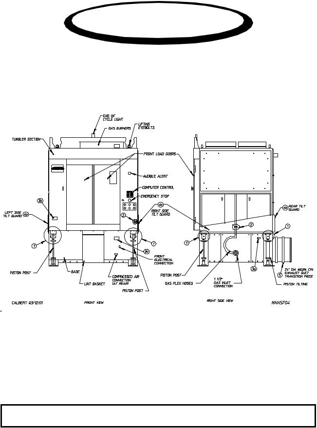
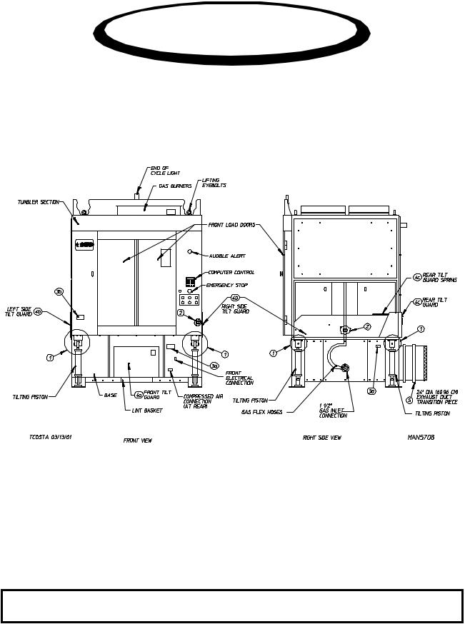
B. DIMENSIONS and COMPONENT IDENTIFICATION/LOCATION
NOTE: ADC reserves the right to make changes in specifications at any time without notice or obligation.
7
NOTE: ADC reserves the right to make changes in specifications at any time without notice or
obligation.
8

NOTE: ADC reserves the right to make changes in specifications at any time without notice or
obligation.
9

SECTION III
INSTALLATION PROCEDURES
Installation should be performed by competent technicians in accordance with local and state codes. In the absence of these codes, the installation must conform to applicable American National Standards: ANSI Z223.1- LATEST EDITION (National Fuel Gas Code) or ANSI/NFPA NO. 70-LATEST EDITION (National Electrical Code) or in Canada, the installation must conform to applicable Canadian Standards: CAN/CGA-B149.1-M91 (Natural Gas) or CAN/CGA-B149.2-M91 or LATEST EDITION (for General Installation and Gas Plumbing) or Canadian Electrical Codes Parts 1 & 2 CSA C22.1-1990 or LATEST EDITION (for Electrical Connections).
A. REASSEMBLY OF DRYER
IMPORTANT: Always keep the basket (tumbler) section of the dryer in an upright position when moving it.
The dryer may be shipped one (1) of two (2) ways: as a complete unit fully assembled and ready for hookup or with the basket (tumbler) section separated from the base. If the dryer is shipped in two (2) pieces, the basket (tumbler) section will have to be lifted onto the base. Use cables through the eyebolts on top of the basket (tumbler) section, or use a forklift for the lifting process.
The tilting dryer is made in many loading and unloading options. Please refer to the reassembly instructions on the following pages for your particular style of dryer.
10
1. Reassembly Instructions For Gas Dryer Shipped In Two (2) Pieces
310 Gas - 1 Door/Forward Tilt
NOTE: ADC reserves the right to make changes in specifications at any time without notice or obligation.
11
310 Gas - 1 Door/Forward Tilt
12
a.Reassembly Instructions For Tilting Gas Dryers:
Lift the basket (tumbler) section onto the base.
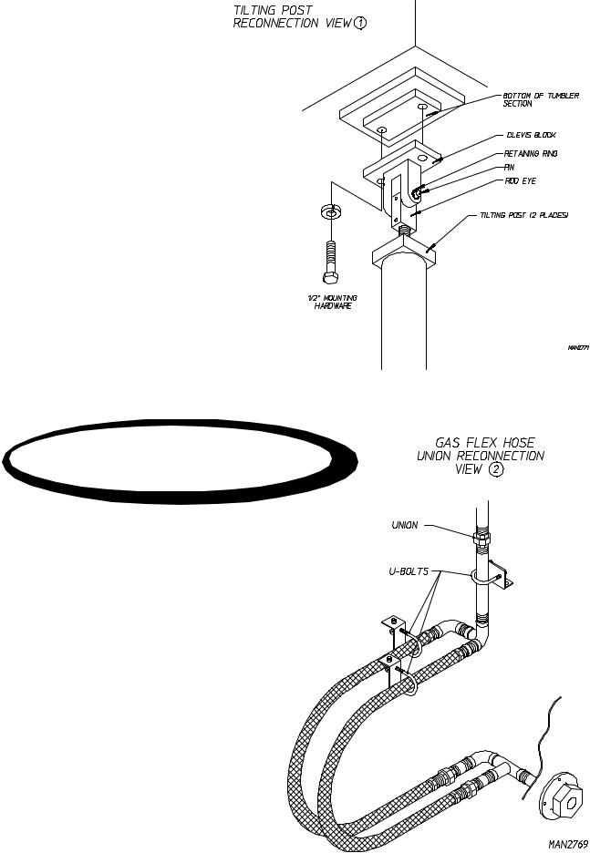
1)Forward tilt dryers have two (2) tilting pistons in the rear of the base. On the top of each piston is a clevis block. Use the four (4) 1/2” x 1-1/8” long hex head bolts with lock washers to secure each piston clevis block to the bottom of the basket (tumbler) section. (Refer to [top] View 1 on the previous page.)
2)The flexible gas hose union is disconnected when the dryer is shipped in two (2) pieces. The flexible gas hoses are located in the right side of the base. Insert the flexible hoses with the union half up through the hole on the bottom of the basket (tumbler) section and retighten the union. The flex hoses must not be kinked. (Refer to [bottom] View 2 on the previous page.)
3)There are two (2) electrical reconnections:
a)A plug and cable is located in the right side of the base. This must be lifted up and reconnected into the mating socket located at the bottom of the right basket (tumbler) section.
b)The basket (tumbler) section power cable must be lifted up from the base and reconnected into the junction box next to the basket (tumbler) drive motor in the left side of the basket (tumbler) section.
Make sure both reconnected cables have enough slack in them to allow the dryer to tilt freely in both directions.
4)Reattach the tilt guard panels:
a)Use 1/4” self-tapping screws to secure the right side and left side tilt guards.
b)Use 1/4” self-tapping screws to secure the rear tilt guards on the rear of the base. Also secure both outside edges of the rear tilt guard to each side guard using sheet metal screws.
5)Secure the 24-inch (60.96 cm) diameter exhaust duct transition piece to the dryer’s rectangular exhaust duct with the 1/4-20 self-tapping screws supplied with the dryer. The exhaust duct exits from the rear of the base.
6)On dryers equipped with an automatic (piston operated) load door, reconnect the two (2) poly-flo air lines that run from the base up to the door pistons.
13
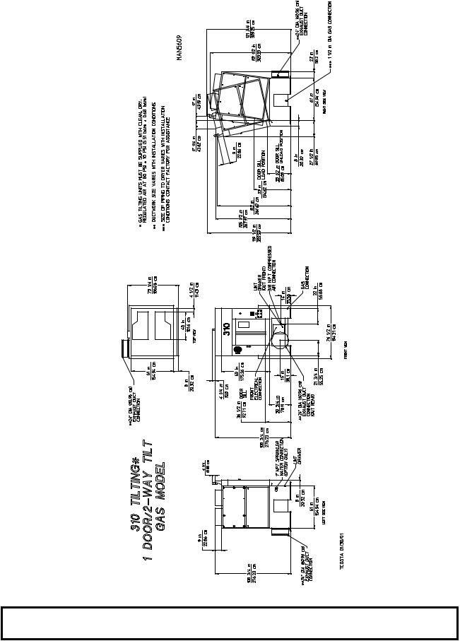
2. Reassembly Instructions For Gas Dryer Shipped In Two (2) Pieces
310 Gas - 1 Door/2-Way Tilt
NOTE: ADC reserves the right to make changes in specifications at any time without notice or obligation.
14
310 Gas - 1 Door/2-Way Tilt
15
a.Reassembly For 1 Door/2-Way Tilt Gas Dryers:
Lift the basket (tumbler) section onto the base.
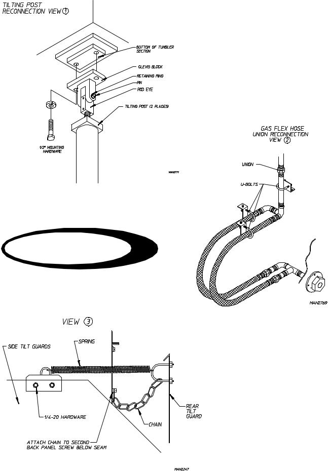
1)2-Way tilt dryers have four (4) tilting pistons in the base, one (1) on each corner. On the top of each piston is a clevis block to the bottom of the basket (tumbler) section. (Refer to [top] View 1 on the previous page.)
2)The flexible gas hose union is disconnected when the dryer is shipped in two (2) pieces. The flexible gas hoses are located in the right side of the base. Insert the flexible hoses with the union half up through the hole on the bottom of the basket (tumbler) section and retighten the union. The flex hoses must not be kinked. (Refer to [middle] View 2 on the previous page.)
3)There are two (2) electrical connections:
a)A plug and cable is located in the right side of the base. This must be lifted up and reconnected into the mating socket located at the bottom of the right basket (tumbler) section.
b)The drive motor wires must be lifted up from the base and reconnected into the junction box next to the basket (tumbler) drive motor in the left side of the basket (tumbler) section.
Make sure both reconnected cables have enough slack in them to allow the dryer to tilt freely in both directions.
4)Reattach the tilt guard panels:
a)Use 1/4-20 x 3/8” hex head bolts with lock washers to bolt the top of the front tilt guard up into the bottom of the front of the basket (tumbler) section.
b)Use 1/4” self-tapping screws to secure the side tilt guards on the top sides of the base.
c)Use 1/4” self-tapping screws to secure the rear tilt guards on the rear of the base.
Reconnect the spring and claw assembly, which connects the rear tilt guard to each side tilt guard. (Refer to [bottom] View 3 on the previous page.) This spring keeps the rear tilt guards close to the dryer’s back as the dryer is tilted forward and back.
d)Reconnect both chains to the back panel.
5)Secure the 24-inch (60.96 cm) diameter exhaust duct transition piece to the dryer’s rectangular exhaust duct with the 1/4-20 self-tapping screws supplied with the dryer. The exhaust duct exits from the rear of the base.
6)On dryers equipped with an automatic (piston operated) load door, reconnect the two (2) poly-flo air lines that run from the base up to the door pistons.
16
3. Reassembly Instructions For Gas Dryer Shipped In Two (2) Pieces
310 Gas - 2 Door/Rear Tilt
(Pass Thru)
NOTE: ADC reserves the right to make changes in specifications at any time without notice or obligation.
17
310 Gas - 2 Door/Rear Tilt
(Pass Thru)
18
a.Reassembly For 2 Door/Rear Tilt (Pass Thru) Gas Dryers:
Lift the basket (tumbler) section onto the base.
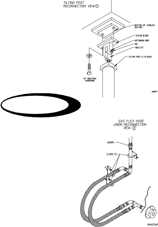
1)Rear tilt dryers have two (2) tilting pistons. The two (2) pistons are in the front corners of the base and there are two (2) piston posts in the rear corners of the base. On the top of both tilting pistons and both piston posts are clevis blocks. Use the four (4) 1/2” x 1-1/8” long hex head bolts with lock washers to secure each clevis block to the bottom of the basket (tumbler) section. (Refer to [top] View 1 on the previous page.)
2)The flexible gas hoses are located in the right side of the base. Insert the flexible hoses with the union half up through the hole on the bottom of the basket (tumbler) section and retighten the union. The flex hoses must not be kinked. (Refer to [bottom] View 2 on the previous page.)
3)There are two (2) electrical reconnections:
a)A plug and cable is located in the right side of the base. This must be lifted up and reconnected into the mating socket located at the bottom of the right basket (tumbler) section.
b)The basket (tumbler) section power cable must be lifted up from the base and reconnected into the junction box next to the basket (tumbler) drive motor in the left side of the basket (tumbler) drive section.
Make sure both reconnected cables have enough slack in them to allow the dryer to tilt freely in both directions.
4)Reattach the tilt guard panels:
a)Use 1/4-20 x 3/8” hex head bolts with lock washers to bolt the top of the front tilt guard up into the bottom of the front of the basket (tumbler) section.
b)Use 1/4” self-tapping screws to secure the right side and left side tilt guards.
5)Secure the 24-inch (60.96 cm) diameter exhaust duct transition piece to the dryer’s rectangular exhaust duct with the 1/4-20 self-tapping screws supplied with the dryer. The exhaust duct exits from the left side of the base.
6)On dryers equipped with two (2) automatic (piston operated) load and unload doors, reconnect the poly-flo air lines that run from the base up to each set of door pistons.
19
 Loading...