


TRACER CH532 Chiller controller User guide
CG-SVU01B-E4

General information
Foreword
These Installation Operation and Maintenance instructions are given as a guide to good practice in the installation, start-up, operation and periodic maintenance by the user of TRACER CH532 chiller controller. They do not contain the full service procedures necessary for the continued successful operation of this equipment. The services of a qualified service technician should be employed, through the medium of a maintenance contract with a reputable service company.
Warranty
Warranty is based on the general terms and conditions of the constructor. The warranty is void if the equipment is modified or repaired without the written approval of the constructor, if the operating limits are exceeded, or if the control system or the electrical wiring is modified.
Damage due to misuse, lack of maintenance, or failure to comply with the manufacturer’s instructions, is not covered by the warranty obligation.
If the user does not conform to the rules of “Maintenance”, it may entail cancellation of warranty and liabilities by the constructor.
Reception
When the unit arrives on site, check it has not been damaged in any way during transport. If damage is observed, or even merely suspected, notify the carrier within 24 hours by registered letter. Notify the local Trane Sales office at the same time. The unit should be totally inspected within 3 days of delivery. If damage is observed, notify the last carrier by registered letter and notify the local sales office.
General information
About this manual
Cautions appear at appropriate places in this instruction manual. Your personal safety and the proper operation of this machine require that you follow them carefully. The constructor assumes no liability for installations or servicing performed by unqualified personnel.
©American Standard Inc. 2004 |
CG-SVU01B-E4 |

Contents
Foreword |
2 |
|
|
Warranty |
2 |
|
|
Reception |
2 |
|
|
General information |
2 |
|
|
TRACER CH532 Presentation |
4 |
|
|
Hardware architecture |
5 |
|
|
Starting/stopping the unit |
9 |
|
|
Menus |
10 |
|
|
Display menu: “Data display” |
11 |
|
|
Customer settings menu: “Settings” |
12 |
|
|
Clock Setting menu: “Clock” |
15 |
|
|
Unit configuration menu: “Configuration” |
17 |
|
|
Alarms |
22 |
|
|
Lon Talk® option |
25 |
|
|
Safety recommendations |
32 |
|
|
Maintenance contract |
32 |
|
|
Training |
32 |
CG-SVU01B-E4 |
3 |
TRACER CH532 Presentation
Important note: This document describes all the functions available on TRACER CH532 with software version 2.0 and explains how to program it.
Certain parameters must only be modified by qualified personnel. Before changing any parameter, always check that the change does not affect the good and safe operation of the equipment. Operation must always stay in the catalogued limits.
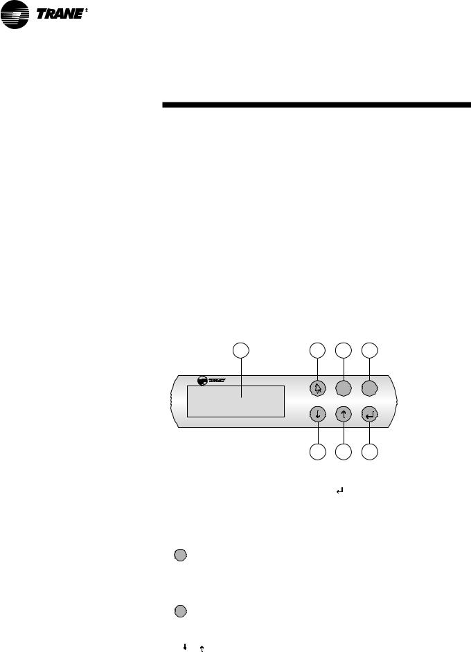
Built-in control terminal features: An LCD display (1), 4 lines x 20 characters with back lighting
6 buttons (2) to (7)
Figure 1 - TRACER CH532 user interface
1 |
2 |
3 |
4 |
Prg Esc
5 6 7
2.  Alarm button:
Used for displaying or manually resetting the alarms. The red LED lights up , when at least one alarm has been detected.
3. Prg Program button:
Allows the various operating parameters to be set (safety parameters, thresholds).
4. Esc Escape button:
Allows the return to default display
5.6. 
 Downward and Upward arrows
Allows management of currently displayed screen and setting of values of control parameters
7  Validation button
Allows to move from line to line in the currently displayed screen and to confirm the set data.
4 |
CG-SVU01B-E4 |

Hardware architecture
Figure 2 - TRACER CH532 inputs and
outputs
9
9
Prg Esc
11
10
CG-SVU01B-E4 |
5 |

Hardware architecture
Table 1 - TRACER CH532 General description
Item |
Description |
1 |
24 V Power supply (G+,GO-) |
2 |
Yellow LED (Power on) |
|
Red LED (Alarm) |
3 |
Fuse (2A , 5x20) |
4 |
Universal Analog inputs: NTC,0/1V,0/10V,0/20mA, 4/20mA) |
5 |
Passive Analog Inputs (NTC,PT1000 , ON/OFF) |
6 |
Analog Outputs (0/10V) |
7 |
Digital Inputs (24Vac / Vdc) |
8 |
Digital Inputs (230Vac or 24Vac / Vdc) |
9 |
Relays digital output |
10 |
User interface |
11 |
Communication interface |
6 |
CG-SVU01B-E4 |

Hardware architecture
Table 2 - Inputs and output summary list
|
TRACER CH532 Medium |
TRACER CH532 Large |
|
Single circuit units |
Dual circuit units |
AI: Leaving water temperature sensor |
B3: NTC |
B3: NTC |
AI: Entering water temperature sensor |
B4: NTC |
B4: NTC |
AI: Ambient temperature sensor |
B5: NTC |
B5: NTC l |
AI: Suction pressure circuit 1 - LP1 transducer |
B1: 4..20mA |
B1: 4..20mA |
AI: Suction pressure circuit 2 - LP2 transducer |
|
B6: 4..20mA |
AI: Discharge pressure circuit 1 - HP1 transducer |
B2: 4..20mA |
B2: 4..20mA |
AI: Discharge pressure circuit 2 - HP2 transducer |
|
B7: 4..20mA |
AI: External water setpoint reset (option) |
B8: 0..10V-0..20mA |
B8: 0..10V-0..20mA |
AI: Unused |
B6, B7 |
B9, B10 |
DI: Compressor C circuit 1 fault |
ID1: 24Vac |
ID1: 24Vac |
DI: Compressor C circuit 2 fault |
|
ID17: 24Vac |
DI: Compressor A circuit 1 fault |
ID3: 24Vac |
ID3: 24Vac |
DI: Compressor B circuit 1 fault |
ID4: 24Vac |
ID4: 24Vac |
DI: Compressor A circuit 2 fault |
|
ID11: 24Vac |
DI: Compressor B circuit 2 fault |
|
ID12: 24Vac |
DI: High pressure Cut-out circuit 1 - HP1 switch |
ID14H: 230Vac |
ID14H: 230Vac |
DI: High pressure Cut-out circuit 2 - HP2 switch |
|
ID15H: 230Vac |
DI: Auxiliary set point On/Off |
ID8: 24Vac |
ID8: 24Vac |
DI: Fans circuit 1 fault |
ID5: 24Vac |
ID5: 24Vac |
DI: Fans circuit 2 fault |
|
ID18: 24Vac |
DI: Circuit 1 On/Off (or Unit On/Off CH 532 medium) |
ID13H: 230Vac |
ID13H: 230Vac |
DI: Circuit 2 On/Off |
|
ID16H: 230Vac |
DI: Water flow control input |
ID2: 24Vac |
ID2: 24Vac |
DI: Water pump 1 fault |
ID9: 24Vac |
ID9: 24Vac |
DI: Water pump 2 fault |
ID10: 24Vac |
ID10: 24Vac |
DI: Faults external reset |
ID6: 24Vac |
ID6: 24Vac |
DI: Cooling/Heating mode switch |
ID7: 24Vac |
ID7: 24Vac |
DI: Unused |
ID11, ID12 |
- |
DO: Compressor A circuit 1 output |
NO7: NO-230Vac |
NO7: NO-230Vac |
DO: Compressors B and C circuit 1 output |
NO8: NO-230Vac |
NO8: NO-230Vac |
DO: Compressor A circuit 2 output |
|
NO13: NO-230Vac |
DO: Compressors B and C circuit 2 output |
|
NO14: NO-230Vac |
DO: Fan 1 output Wye (Y) contactor - circuit 1 |
NO3: NO-230Vac |
NO3: NO-230Vac |
DO: Fan 1 output Delta (D) contactor - circuit 1 |
NO4: NO-230Vac |
NO4: NO-230Vac |
DO: Fan 2 output circuit 1 |
NO5: NO-230Vac |
NO5: NO-230Vac |
DO: Fan 3 output circuit 1 |
NO6: NO-230Vac |
NO6: NO-230Vac |
DO: Fan 1 output Wye (Y) contactor - circuit 2 |
|
NO15: NO-230Vac |
DO: Fan 1 output Delta (D) contactor - circuit 2 |
|
NO16: NO-230Vac |
DO: Fan 2 output circuit 2 |
|
NO17: NO-230Vac |
DO: Fan 3 output circuit 2 |
|
NO18: NO-230Vac |
DO: Water pump 1 |
NO1: NO-230Vac |
NO1: NO-230Vac |
DO: Water pump 2 |
NO2: NO-230Vac |
NO2: NO-230Vac |
DO: Antifreeze heater |
NC12: NO-230Vac |
NC12: NO-230Vac |
DO: Circuit 1 fault |
NO9: NO-230Vac |
NO9: NO-230Vac |
DO: Circuit 2 fault |
|
NO11: NO-230Vac |
DO: Unit status or additional heating demand |
NO10: NO-230Vac |
NO10: NO-230Vac |
DO: Unused |
NO11, NO13 |
- |
AO: Speed inverter - fan circuit 1 - HP1 output |
Y1: 0..10V |
Y1: 0..10V |
AO: Speed inverter - fan circuit 2 - HP2 output |
|
Y2: 0..10V |
AO: 4-way valve circuit 1 |
Y3: 0..10V + CONVONOFF |
Y3: 0..10V + CONVONOFF |
AO: Unused |
Y4 |
Y4 |
AO: 4-way valve circuit 2 |
|
Y5: 0..10V + CONVONOFF |
AO: Unused |
|
Y6 |
AO: Unused |
Y2 |
Y2 |
Legend: |
|
|
AI: Analog Input |
|
|
DI: Digital Input |
|
|
AO: Analog Output |
|
|
DO: Digital Output |
|
|
CONVONOFF: ON/OFF converter |
|
|
CG-SVU01B-E4 |
7 |
Hardware architecture
TRACER CH532 offers customer the possibility to use inputs or outputs in order to:
-use an external water setpoint reset using an analog input (refer to figure 3)
-use an auxiliary setpoint
-connect a remote on/off of the unit or a circuit
-reset faults
-connect a remote Cooling/Heating switch
-return a circuit fault
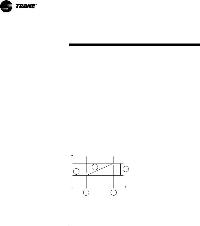
Note: External water setpoint
Based on a external signal input, it will be possible to offset the active setpoint from 0°C to 20°C. This function can be used in conjunction with the automatic setpoint reset function.
Figure 3
setpoint |
|
5 |
4 |
1 |
|
||
|
|
||
Water |
|
|
|
|
|
|
|
|
2 |
Ambient |
3 |
|
temperature |
1.Leaving water temperature setpoint
2.Minimum value
3.Maximum value
4.Reset = 20°C
5.Active setpoint
Table 3: Customer Inputs and output summary list
|
|
TRACER CH532 Medium |
TRACER CH532 Large |
|
|
Single circuit units |
Dual circuit units |
AI |
External water setpoint reset (option) |
B8: 0..10V-0..20mA |
|
DI |
Auxiliary setpoint On/Off |
ID8: 24Vac |
|
DI |
Circuit 1 On/Off (or Unit On/Off |
|
|
|
for single circuit units) |
ID13H: 230Vac |
|
DI |
Circuit 2 On/Off |
- |
ID16H: 230Vac |
DI |
Faults external reset |
ID6: 24Vac |
|
DI |
Cooling/Heating mode switch |
ID7: 24Vac |
|
DO |
Circuit 1 fault |
NO9: NO-230Vac |
|
DO |
Circuit 2 fault |
- |
NO11: NO-230Vac |
DO |
Unit status or additional |
|
|
|
heating demand |
NO10: NO-230Vac |
|
Legend:
AI: Analog Input
DI: Digital Input
DO: Digital Output
8 |
CG-SVU01B-E4 |
Starting/stopping the unit
Once the unit is powered on (main disconnect switch closed) TRACER CH532 returns to the following display:
TRACER CH532 |
V2.0 |
01/05/04 |
00:00 |
Water Temp |
20.0°C |
OFF BY KEYB. |
|
|
|
Line 2 gives current date and time Line 3 gives current leaving water temperature
Line 4 gives the unit status:
OFF BY KEYB = Local stop UNIT ON = Unit running
Pressing Esc from any screen will return to this screen.
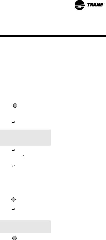
1. Starting the unit:
1.Press 
2.Following screen will be displayed:
Status Unit
OFF BY KEYB.
Switch on unit ? |
N |
3.Press 
4.Press  or
or  to change from “N” to “Y”
5.Press  . Following screen will be displayed:
TRACER CH532 |
V2.0 |
01/05/04 |
00:00 |
Water Temp |
20.0°C |
UNIT ON |
|
|
|
2.Stopping the unit
1.Press Esc to exit from any menu and return to default display.
2.Press  for 3 seconds unit will stop, and following screen will be displayed:
Unit Switched Off
3. Press Esc to return to default display
Note: In case of power failure unit will restart in the state (operating mode, setpoints…) it was in before the power failure and default screen will be displayed.
CG-SVU01B-E4 |
9 |
Menus
TRACER CH532 allows the user to access 4 menus to display or adjust operation parameters:
•“Data display” menu - This menu allows the user to visualize all operation parameters:
-Water and air temperatures
-Refrigerant pressures
-Saturated refrigerant temperatures
-Compressors status
-Compressor running hours
-Number of compressors starts
-Unit operating mode
-Compressors failures counters
•“Settings” menu - This menu is password protected. It allows access to the settings of:
-Setpoints
-Offset of cooling and heating setpoints
-Unit operation validation
-Customer inputs and outputs
•“Clock” menu - This menu is password protected. It allows access to the settings of:
-Day of the week, hour, date
-Daily or weekly program
-Hourly zone program
•“Configuration” menu - This menu is password protected. It allows to adjust or change:
-Unit definition
-Compressors timers
-High pressure control
-Dead band, antifreeze and heater setpoints
-Type of sensors and transducers
-Operation protections
-Cooling mode limitations
-Defrost parameters
-Compressor alarms
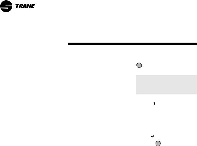
Accessing the menus
From any screen displayed, press
Esc , TRACER CH532 will then display the following screen:
Data Display
Settings
Clock
Configuration
1.  or
or  allow the cursor to move from line to line thus selecting one of the 4 menus.
Note: The selection is displayed in capital characters
2.Once one line is selected, press  to validate the choice.
3.Pressing Esc will exit the menu selection mode and return to default display.
10 |
CG-SVU01B-E4 |
 Loading...