


Smartups
120 VAC
Uninterruptible Power Source Fonte de Energia Ininterrupta
Models 450, 700, 1000, 1400, 2200, 3000
Português English
User’s Guide/Guia do Usuário English/Português
Part Number 990-7042A
Revision 2 |
Revised 7/97 |

Contents/Índice |
|
English ......................................................................................... |
1 |
Português ................................................................................... |
27 |
Please note: The troubleshooting section (section 8) offers solutions for most of the difficulties you may encounter with this unit. Before calling customer service, please have available your unit’s serial number (see label on the rear of the unit). A returned materials authorization (RMA) number is required for all return shipments to APC. Do not send return shipments to APC without an RMA number. See section 9.
Por favor, observe: A seção sobre resolução de problemas (seção 8) oferece soluções para a maioria das dificuldades que você pode encontrar com o No-Break. Antes de ligar para o serviço de atendimento ao cliente, por favor, tenha em mãos o número de série de seu No-Break (veja o selo na parte de trás do No-Break). É necessário um número de autorização para devolução de materiais (RMA) em todas as devoluções para a APC. Não envie produtos para devolução à APC sem um número de RMA. Veja a seção 9.
Serial number:/Número de série:
Português English
Toll free technical support:
Assistência Técnica Gratuita:
Brasil |
0800-12-7221 |
United States and Canada |
1-800-800-4272 |
Ireland |
1-800-702000 |
U. K. |
0800-132990 |
Others/Outros:
+1 401 789 5735 (USA) or
+353 91 702020 (Ireland)
Return shipment addresses:
Endereços para devolução de produtos:
American Power Conversion Corporation 132 Fairgrounds Road
P. O. Box 278
West Kingston, Rhode Island 02892 USA
American Power Conversion Corporation (A. P. C.) b. v.
Ballybritt Business Park Galway
Ireland
Entire contents copyright © 1997 American Power Conversion. All rights reserved; reproduction in whole or in part without permission is prohibited. All other trademarks are the property of their respective owners.

1. |
Introduction............................................................................ |
1 |
2. |
Safety ..................................................................................... |
4 |
3. |
Presentation ........................................................................... |
5 |
4. |
Installation .............................................................................. |
8 |
5. |
Operation ............................................................................. |
11 |
6. |
Alarms .................................................................................. |
15 |
7. |
Options ................................................................................. |
16 |
8. |
Troubleshooting..................................................................... |
17 |
9. |
Service .................................................................................. |
18 |
10. |
Replacing the battery ............................................................. |
19 |
11. |
Storage ................................................................................. |
22 |
12. |
Specifications ......................................................................... |
23 |
13. |
How to Determine On-battery Run Time ................................. |
24 |
14. |
User Configuration Items ........................................................ |
26 |
1.Introduction
1.1Thank you!
Thank you for selecting this uninterruptible power source. It is designed for many years of reliable, maintenance-free service.
Important!
Please read this manual. It provides safety, installation, and operating instructions that will help you get the fullest performance and service life from your unit. This manual describes the inner workings of the unit and how they relate to providing superior protection from utility power problems such as blackouts, brownouts, sags, swells, EMI/RFI noise, and surges. The manual includes instructions for obtaining factory service if necessary.
If you have a problem with the unit, please refer to this manual before calling customer service. The troubleshooting section (section 8) can help with most situations typically encountered when using the unit.
Please save the packaging materials!
The unit’s shipping materials are designed with great care to provide protection during shipping. These materials are invaluable if you ever have to return the unit for service. Damage sustained during transit is not covered under the warranty.
English
1
1.2 Radio Frequency Interference
450 VA - 1400 VA
Warning: Changes or modifications to this unit not expressly approved by the party responsible for compliance could void the user’s authority to operate the equipment.
Note: This equipment has been tested and found to comply with the limits for a Class B digital device, pursuant to Part 15 of the FCC Rules and the Class B limits for radio noise emissions from digital apparatus set out in the Radio Interference Regulations of the Canadian Department of Communications. These limits are designed to provide reasonable protection against harmful interference in a residential installation. This equipment generates, uses and can radiate radio frequency energy and, if not installed and used in accordance with the instructions, may cause harmful interference to radio communications.
However, there is no guarantee that interference will not occur in a particular installation. If this equipment causes interference to radio or television reception, which can be determined by turning the equipment off and on, the user is encouraged to try to correct the interference by one or more of the following measures:
■reorient the receiving antenna
■increase the separation between the equipment and the receiver
■connect the equipment to an outlet on a circuit different from that to which the receiver is connected
■consult the dealer or an experienced radio/TV technician for help.
Shielded communications interface cables must be used with this product.
2200 VA and 3000 VA
Warning: Changes or modifications to this unit not expressly approved by the party responsible for compliance could void the user's authority to operate the equipment.
Note: This equipment has been tested and found to comply with the limits for a Class A digital device, pursuant to Part 15 of the FCC Rules and the Class A limits for radio noise emissions from digital apparatus set out in the Radio Interference Regulations of the Canadian Department of Communications. These limits are designed to provide reasonable protection against harmful interference when the equipment is operated in a commercial environment. This equipment generates, uses, and can radiate radio frequency energy and, if not installed and used in accordance with the instruction manual, may cause harmful interference to radio communications. Operation of this equipment in a residential area is likely to cause harmful interference in which case the user will be required to correct the interference at his own expense.
Shielded signal cables must be used with this unit to ensure compliance with the Class A FCC limits.
2

1.3 Theory of Operation
English
This high-performance, line-interactive, uninterruptible power source provides clean, reliable, AC power to computer systems — protecting them from power blackouts, brownouts, swells, sags, surges, and interference.
Normally, the unit operates “on-line,” supplying power from theutility input to the load (workstation, server, or other device). The converter circuitry is used to maintain an optimal float charge level on thebattery.
When the utility fails, the converter supplies AC power to the load and the disconnect switch opens. The loads operate normally until shut down or until the battery is exhausted. The unit automatically transfers the load back to utility power when the line voltage returns to normal.
The unit also provides surge protection and EMI/RFI filtering, as well as Smart-Boost™ and SmartTrim™, which correct high and low input voltage without drawing power from the battery. Output control uses the unit’s remote interface to turn the load on or off, without disabling other unit functions.
1.4 Features
Intelligent Battery Management
The unit provides visual and audible indications of the battery’s present status including capacity, low battery condition, and replace battery condition.
The unit exercises the battery during its self-test, and detects a weak battery before it is put into service. The unit normally performs a self-test at power up and every 14 days. Self-tests can also be conducted manually with the on/test button at any time.
The unit features user-replaceable batteries. Batteries can be replaced without having to remove power from the loads or send the unit in for service.
Computer Interface and Accessory Slot
Advanced monitoring, power management, and customizing functions are available through the computer interface and accessory slot. See section 7 for more information.
3

2. Safety
CAUTION!
■To reduce the risk of electric shock in conditions where load equipment grounding cannot be verified, disconnect the unit from the AC power outlet before installing a computer interface or accessory slot signal cable. Reconnect the power cord only after all signaling connections are made.
■Connect the unit to a two-pole, three-wire grounding AC power outlet. The receptacle must be connected to appropriate branch protection (fuse or circuit breaker). Connection to any other type of receptacle may result in a shock hazard and violate local electrical codes.
■The unit has an internal energy source (the battery). The output may be energized when the unit is not connected to an AC power outlet.
■To deenergize the outputs of the unit, first press the Off button for more than one second to switch the unit off. Next disconnect the unit from the AC power outlet. To deenergize the unit completely, disconnect the battery. See section 10.
■This unit’s protective Earth conductor carries the leakage current from the load devices (computer equipment). This unit generates approximately 1.5 mA of leakage current. To ensure a safe limit of 3.5 mA, limit the total leakage current of the load devices to 2 mA.
■Use of this equipment in life support applications where failure of this equipment can reasonably be expected to cause the failure of the life support equipment or to significantly effect its safety or effectiveness is not recommended.
4
3.Presentation
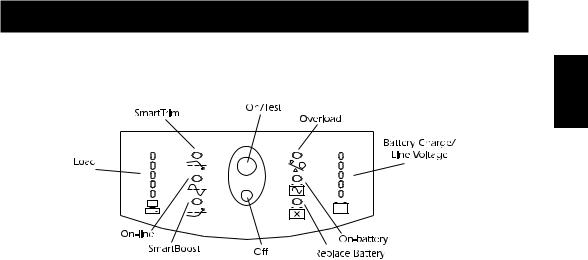
3.1Front panel
With the unit plugged in, press the on/test button to turn on the unit and power the loads. See Sec. 5.1. On/test also activates the unit’s self-test and utility line voltage displays. See sections 5.3 and 5.6. The overload LED lights when the loads connected to the unit exceed the unit’s capacity. See section 6.2.
The battery charge/line voltage display shows the present battery charge as a percentage of battery capacity. See section 5.5. It also displays the voltage of the utility line. See section 5.6.
The on-battery LED comes on when the unit is supplying battery power to the loads.
The replace battery LED comes on when the unit’s battery is no longer useful and must be replaced. See section 10.
Press the off button to turn off the unit and the load. See section 5.2.
The SmartBoost LED comes on when the unit is correcting a low utility voltage condition. The loads receive normal power.
The on-line LED comes on when the unit is supplying utility power to the loads. The load display shows the power being drawn by the load. See section 5.4.
The SmartTrim LED comes on when the unit is correcting a high utility voltage condition. The loads receive normal power.
English
5

3.2 Rear Panel
2200 and 3000 VA
1000 and 1400 VA
6
English
450 and 700 VA
Use the computer interface port for unit monitoring and control. See section 7.
The configuration button changes the unit’s sensitivity to utility voltage variations and the low battery warning interval. See sections 5.9 and 5.10.
The configuration LED indicates the voltage sensitivity setting and the low battery warning interval. See sections 5.9 and 5.10.
The site wiring fault indicator comes on when the unit is connected to an improperly wired AC power outlet. See section 4.8.
The output circuit breakers (2200 VA and 3000 VA models only) trip when the connected loads exceed the protected receptacle’s capacity. The center plunger of the circuit breakers extend when tripped.
The input circuit breaker trips when loads exceed the unit’s capacity. The center plunger of the circuit breaker extends when tripped.The paddle handle on 3000VA model input circuit breaker shows“off” when tripped.
Use the transient voltage surge suppression(TVSS) ground connector for the ground leads of telephone or network line protectors. See section 4.9.
The input power connector is a power cord with a NEMA 5-15P connector for 450 through 1400 VA models. See the table below for input power connectors on 2200 VA and 3000 VA models.
The output power receptacles are NEMA 5-15R type. Optional output power receptacle kits are available from the factory for the 2200 VA and 3000 VA models. See your dealer or call the number at the front of this manual for more information.
Optional accessories can be installed in the accessory slot. See section 4.4 and section 7.
Use the battery pack connector to connect the optional external battery pack (3000 VA model only).
7
2200 VA and 3000 VA Input Power Connectors
|
Standard input |
Maximum output |
Available input |
Maximum output |
|
Model |
power with standard |
power with available |
|||
power connector |
power connectors |
||||
|
connector |
connector |
|||
|
|
|
|||
|
|
|
|
|
|
|
|
|
NEMA 5-15 |
1200 VA/1200 W |
|
|
|
|
|
|
|
2200 VA |
NEMA 5-20P |
1600 VA/1600 W |
NEMA L5-20 |
1600 VA/1600 W |
|
|
|
|
|
|
|
|
|
|
NEMA L5-30 |
2200 VA/2200 W |
|
|
|
|
|
|
|
3000 VA |
NEMA 5-30P |
2550 VA/2250 W |
NEMA L5-50 |
3000 VA/3000 W |
|
|
|
|
|
|
4. Installation
To obtain warranty coverage fill out and return the warranty registration card now.
4.1 Inspection
Inspect the unit upon receipt. Notify the carrier and dealer if there is damage. The packaging is recyclable; save it for reuse or dispose of it properly.
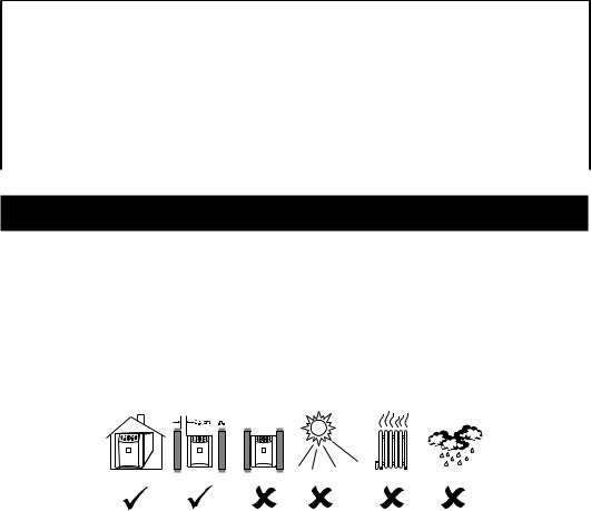
4.2 Placement
Install the unit in a protected area with adequate air flow and free of excessive dust. Do not operate the unit where the temperature and humidity is outside the specified limits. See section 12. Allow the unit to come to room temperature before continuing.
4.3 Protection Strategies
This unit provides high performance power line protection to the loads. There are, however, other potential entry points for damaging surges in information systems. These include serial ports (RS232, RS-422, RS-485, etc.), parallel ports, telephone lines, and network connections. These other entry points must be considered in developing a comprehensive system protection strategy. Contact your dealer or call the number in the front of this manual for information on a complete set of related products designed to accomplish total system protection.
8
Sensitive information systems can be further safeguarded by following these guidelines: ■ Verify that all electrical outlets are properly grounded.
■ Connect information systems to a different electrical service branch than heavy motor loads
|
like air conditioners, copiers, refrigerators, and heavy industrial machinery. |
English |
|
■ |
Plug all power protection and information system equipment into the same branch where |
||
|
|||
|
possible. |
|
|
|
|
|
4.4 Install Accessory (Optional)
Some accessories connect to the computer interface (DB-9) port, while others install in the accessory slot. See the literature accompanying the accessory to determine proper installation. The screws holding the slot cover are #2 Phillips head type.
To use the computer interface port, connect the accessory to the DB-9 connector and tighten down the connector’s screws.
Connect the optional battery pack (3000 VA model only) according to the instructions with the battery pack.
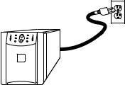
4.5 Connect to Utility
Plug the unit into a two-pole, three-wire, grounding receptacle only. Avoid using extension cords and adapter plugs.
4.6 Charge the Battery
The unit charges its battery whenever it is connected to utility power. For best results, charge the battery for 2.5 hours before use. It is acceptable to use the unit without first charging the battery, but on-battery run time may be reduced until the battery charges.
9
4.7 Connect the Loads
Plug the loads into the output connectors on the rear of the unit. To use the unit as a master on/ off switch, make sure that all of the loads are switched on.
Caution: Do not connect a laser printer to the unit along with other computer equipment unless the unit is rated 1400 VA or higher. A laser printer periodically draws significantly more power than when idle, and may overload the unit. Verify that the unit can support the loads when the printer is in full operation (printing).
Test the system with all loads operating to make sure that the unit is not overloaded. See section 6.2.
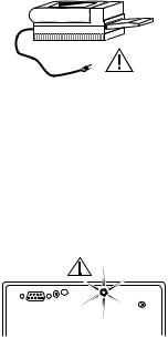
4.8 Check the Site Wiring Fault Indicator
After plugging in the loads and the unit, check the site wiring fault indicator on the rear panel. See section 3.2 for the location of the indicator on the back panel. It lights if the unit is plugged into an improperly wired AC power outlet. Wiring faults detected include missing ground, hot-neutral polarity reversal, and overloaded neutral circuit.
Caution: If the unit indicates a site wiring fault, get a qualified electrician to correct the building wiring.
4.9 Connect Ground Leads to TVSS Connector (Optional)
The unit features a TVSS connector for connecting the ground lead on transient voltage surge-sup- pression (TVSS) devices such as telephone and network line protectors. The TVSS connector provides grounding through the unit’s power cord ground conductor.
Note: Do not use the TVSS connector if the site wiring fault indicator is lit.
To make a connection to the TVSS connector, loosen the screw and connect the surge suppression device’s ground lead. See section 3.2 for the location of the connector. Tighten the screw to secure the lead.
10
5.Operation
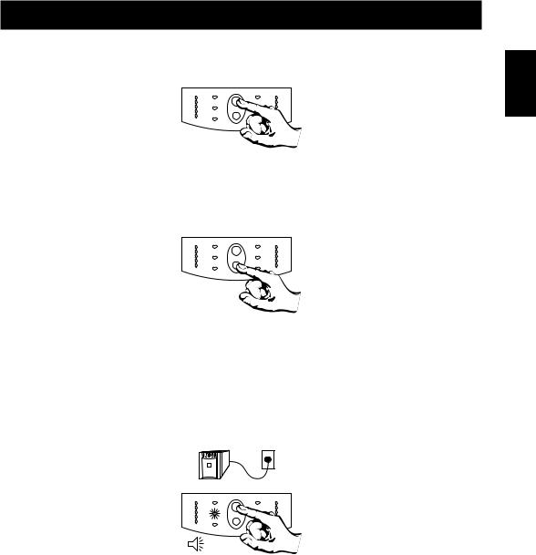
5.1Switch On
With the unit plugged in, press the on/test (upper) button to supply power to the loads. The loads are immediately powered while the unit beeps and performs a self-test. See section 5.3.
5.2 Switch Off
To switch off the unit’s output power, press the off (lower) button. It may be convenient to use the on and off buttons of the unit as a master on/off switch for the protected equipment.
Note: The unit is on (the internal processor is operating) whenever it is plugged in and utility voltage is present. Even when switched off the unit maintains the battery charge and will respond to commands received through the computer interface port and the accessory slot.
5.3 Self-test
Use the self-test to verify both the operation of the unit and the condition of the battery. With the unit plugged in to normal utility power, activate the self-test by pressing the on/test button until the unit beeps and the on-line LED flashes.
Note: By default the unit performs a self-test at power up and once every two weeks.
English
11
During the self-test, the unit briefly operates the loads on-battery (the on-battery LED comes on). If the unit passes the self-test, it returns to on-line operation. The on-battery LED goes off and the on-line LED goes on steady.
If the unit fails the self-test it immediately returns to on-line operation and lights the replace battery LED. The loads are not affected. Recharge the battery overnight and perform the self-test again. If the replace battery LED is still on, see section 10 for information on replacing the battery.
5.4 Load Bar Graph
The 5-LED display on the left of the front panel shows the power drawn from the unit by the load. The display indicates the percentage of the unit’s rated capacity. For example, if three LEDs are lit, the load is drawing between 50% and 67% of the unit’s capacity.
If all five LEDs light, thoroughly test your complete system to make sure that the unit will not become overloaded.
If the unit is overloaded, the overload LED lights and an alarm sounds. See section 6.2.
5.5 Battery Charge Bar Graph
The 5-LED display on the right of the front panel shows the present charge of the unit’s battery as a percentage of the battery’s capacity. When all five LEDs light, the battery is fully charged. When the lowest LED is flashing, the battery can supply less than two minutes of run time for the load.
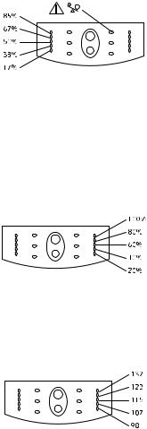
5.6 Utility Voltage Bar Graph
This unit has a diagnostic feature that displays the utility voltage. With the unit plugged into the normal utility power, press and hold the on/test button to see the utility voltage bar graph display. After four seconds the 5-LED display on the right of the front panel shows the utility input voltage. Refer to the list for the voltage reading.
12
The display indicates that the voltage is between the displayed value from the list and the next higher value. For example, with three LEDs lit, the input voltage is between 115 and 123 VAC.
If no LEDs come on and the unit is plugged into a working AC power outlet, the line voltage is extremely low.
If all five LEDs come on, the line voltage is extremely high and should be checked by an electrician.
Note: The unit will start a self-test as part of this procedure. The self-test does not affect the voltage display.
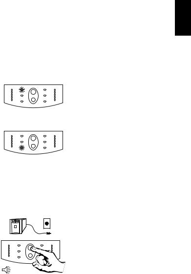
5.7 SmartBoost and SmartTrim
The unit automatically corrects high and low utility voltages so that the loads receive voltage within the normal range.
The unit’s SmartTrim LED comes on to indicate that the unit is compensating for a high voltage level.
The SmartBoost LED comes on to indicate that the unit is compensating for a low voltage condition.
SmartTrim and SmartBoost indications are advisory. No user action is required. To check the utility voltage use the utility voltage display. See section 5.6.
5.8 Cold Start
When the unit is off and there is no utility power, use the cold start feature to apply power to the loads from the unit’s battery. Press the on/test button until the unit beeps. Release the button during the beep and the loads are powered within 4 seconds. Cold start is not a normal operating condition.
English
13
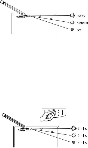
5.9 Voltage Sensitivity
The unit detects line voltage distortions such as spikes, notches, dips, and swells, as well as distortions caused by operation with inexpensive fuel powered generators. By default, the unit reacts to distortions by transferring to on-battery operation to protect the loads. Where power quality is poor, the unit may frequently transfer to on-battery operation. If the loads can operate normally under such conditions, battery capacity and service life may be conserved by reducing the sensitivity of the unit.
To reduce unit’s sensitivity, press the configuration button on the rear panel. Use a pointed object such as a pen to press the button. Press it once to set the unit’s sensitivity to reduced. Press it again to set the sensitivity to low. Press the button again to reset normal sensitivity.
When the unit is set to normal sensitivity, the configuration LED is brightly lit.When it is set to reduced sensitivity, the LED is dimly lit.When it is set to low sensitivity, the LED is off.
5.10 Low Battery Warning Interval
By default, the low battery warning occurs when there are approximately two minutes of on-bat- tery run time remaining. This may not be enough time to gracefully shut down some protected computer systems. To change the warning interval, press the rear panel configuration button while pressing and holding the front-panel on/test button. Use a pointed object such as a pen to press the configuration button.
Press the configuration button once to set the low battery warning interval to approximately five minutes. Press it again to set the interval to approximately seven minutes. Press the button again to reset the interval to two minutes.
14
 Loading...