


APC Smart-UPS® RT
1000/2000 VA
220/230/240 VAC
Tower/Rack Mount 2U
Uninterruptible Power Supply
User Manual
English
990-1060B 12/2005
1: SAFETY INFORMATION
American Power Conversion Corporation (APC) is the leading national and international manufacturer of state-of-the-art uninterruptible power supplies, redundant switches, power management software, and related equipment. APC products protect hardware, software, and data from the threat of power disturbances in business and government offices throughout the world.
The APC Uninterruptible Power Supply (UPS) is designed to prevent blackouts, brownouts, sags, and surges from reaching your computer and other valuable electronic equipment. The UPS filters out small utility line fluctuations and isolates your equipment from large disturbances by internally disconnecting from the utility line. The UPS provides continuous power from its internal battery until the utility line returns to safe levels.
Changes or modifications to this unit not expressly approved by the party responsible for compliance could void the warranty.
HANDLING SAFETY
Be careful. Do not lift heavy loads without assistance.
<18 kg (<40 lb) |
32–55 kg (70–120 lb) |
|
18–32 kg (40–70 lb) |
>55 kg (>120 lb) |
|
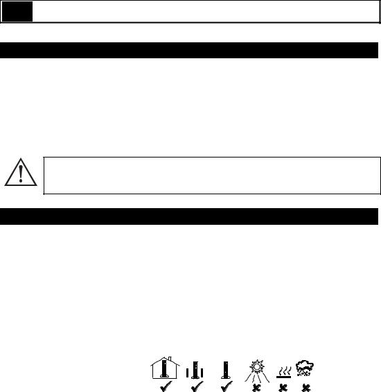
This equipment is intended for installation in a temperature-controlled indoor area free of conductive contaminants. Refer to Specifications at the APC web site for the actual temperature range.
ELECTRICAL SAFETY
•To reduce the risk of fire, connect only to a circuit provided with a 30 Amp maximum branch circuit overcurrent protection in accordance with the National Electrical Code ANSI/NFPA or country specific electrical code.
•Do not work alone under hazardous conditions.
•Check that the power cord(s), plug(s), and sockets are in good condition.
•To reduce the risk of electric shock when grounding, disconnect the equipment from the AC power outlet before installing or connecting to other equipment. Reconnect the power cord only after all connections are made.
•Use one hand, whenever possible, to connect or disconnect signal cables to avoid a possible shock from touching two surfaces with different electrical grounds.
•Connect the equipment to a three wire AC outlet (two poles plus ground). The receptacle must be connected to appropriate branch circuit/mains protection (fuse or circuit breaker). Connection to any other type of receptacle may result in a shock hazard.
1 |
990-1060B 12/2005 |

•In order to maintain compliance with the EMC directive, output cords attached to the UPS should not exceed 10 meters in length.
DEENERGIZING SAFETY
•If the equipment has an internal energy source (battery), the output may be energized when the unit is not connected to an AC power outlet.
•To deenergize pluggable equipment: first press the OFF button for more than one second to switch the equipment off. Disconnect the equipment from the AC power outlet. Unplug the battery connector. Push the ON button to deenergize the capacitors.
•Pluggable equipment includes a protective earth conductor that carries the leakage current from the load devices (computer equipment). Total leakage current must not exceed 3.5 mA.
•Use of this equipment in life support applications where failure of this equipment can reasonably be expected to cause the failure of the life support equipment or to significantly affect its safety or effectiveness is not recommended.
BATTERY SAFETY
•This equipment contains potentially hazardous voltages. Do not attempt to disassemble the unit. The only exception is for equipment containing batteries. Battery replacement using the procedures below is permissible. Except for the battery, the unit contains no user serviceable parts.
Repairs are to be performed only by factory trained service personnel.
•Do not dispose of batteries in a fire. The batteries may explode.
•Do not open or mutilate batteries. They contain an electrolyte that is toxic and harmful to the skin and eyes.
•Do not connect the terminals of a battery or battery pack with a wire or other electrically conductive objects.
•To avoid personal injury due to energy hazard, remove wristwatches and jewelry such as rings when replacing the batteries. Use tools with insulated handles.
•Replace batteries with the same number and type of batteries or battery packs as originally installed in the equipment.
BATTERY REPLACEMENT AND RECYCLING
See your dealer or visit the APC web site, www.apc.com/support for information on replacement battery kits and battery recycling.
Be sure to return the spent battery to APC for recycling. Ship it to APC in the replacement battery packing material.
990-1060B 12/2005 |
2 |
2: INSTALLATION
UNPACKING
Inspect the UPS upon receipt. APC designed robust packaging for your product. However, accidents and damage may occur during shipment. Notify the carrier and dealer if there is damage.
The packaging is recyclable; save it for reuse or dispose of it properly.
Check the package contents. The shipping package contains the UPS (with batteries disconnected); its front bezel (packaged separately); feet (required in tower configuration); and a literature kit containing a software CD, one serial cable, power cord(s), screws for the feet, and product documentation.
The UPS is shipped with the battery disconnected and the front bezel removed. You will connect the battery and install the plastic bezel (described later) during the installation procedure.
POSITIONING THE UPS
Place the UPS where it will be used. The UPS is heavy. It requires two people for installation due to its weight. To lighten the UPS, you may remove the battery while you position the UPS. See Removing the Battery Pack, below, for instructions. Select a location sturdy enough to handle the weight.
You must install the UPS in a protected area that is free of excessive dust and has adequate airflow. Ensure the air vents on the front and rear of the UPS are not blocked. Allow at least one inch of space on each side.
Do not operate the UPS where the temperature and humidity are outside the specified limits. Refer to the Specifications at the APC web site (www.apc.com).
Placement
3 |
990-1060B 12/2005 |

INSTALLATION
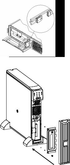
1. ATTACH THE SUPPORT FEET
If the UPS is to be operated in Tower Configuration the support feet must be attached for proper stability.
1.Locate the two feet and the plastic bag containing the four screws packed with the UPS.
2.Gently lay the UPS on its side as shown.
3. Use the screws to attach the support feet securely to the bottom of the UPS in the holes provided.
4. Carefully stand the unit upright upon the support feet.
2. REMOVE THE BATTERY DOOR
1. Facing the front of the UPS, locate the battery compartment. The battery connector is hanging from cables that lead through a hole in the battery door and into the battery compartment.
2.Use a screwdriver to remove the two battery door screws located at the left side corners of the battery door. Set the screws aside in a safe place. You will replace them later.
3.Remove the battery door by sliding it along the
cables and past the connector (the connector will fit through the hole in the battery door). Set the battery door aside.
990-1060B 12/2005 |
4 |
3. CONNECT THE BATTERY
1.To connect the battery, push the battery connector into the receptacle in the battery compartment. Press firmly to ensure a tight connection. You will hear a “snap” when the connector is seated properly.
2.Push the battery cables and white cord into the space with the battery connector.
4.ATTACH BATTERY DOOR AND FRONT BEZEL
1.Replace the battery door and screw the two battery door screws back into the corners of the battery door. The battery door will cover the battery cables and white cord.
2.The UPS is shipped with the front bezel removed and packed separately within the main box. Unpack the bezel and hold it with the cut-
out section on top. Slide the tab on the bottom of the bezel into the slot on the bottom of the UPS. Gently snap the top of the bezel into place. The bezel can be removed by carefully unsnapping the top, and then sliding the bezel up and out of the tab on the bottom of the UPS.
5. CONNECT THE EQUIPMENT TO THE UPS AND CONNECT THE UPS TO THE AC POWER SUPPLY
1.On the back panel, plug the female end of the power cord into the receptacle. Then plug the male end into a two-pole, three-wire, grounding receptacle. Avoid using extension cords and adapter plugs.
2.Connect the equipment to the UPS using the power cords provided with the equipment.
3.Turn on all connected equipment. To use the UPS as a master ON/OFF switch, be sure all connected equipment is switched on. The equipment will not be powered until the UPS is turned on.
5 |
990-1060B 12/2005 |
 Loading...