


 Loading...
Operation, Maintenance,
and Troubleshooting
NetworkAIR® FM DX
Precision Air Conditioner
60 Hz
American Power Conversion Legal Disclaimer
The information presented in this manual is not warranted by the American Power Conversion Corporation to be authoritative, error free, or complete. This publication is not meant to be a substitute for a detailed operational and site specific development plan. Therefore, American Power Conversion Corporation assumes no liability for damages, violations of codes, improper installation, system failures, or any other problems that could arise based on the use of this Publication.
The information contained in this Publication is provided as is and has been prepared solely for the purpose of evaluating data center design and construction. This Publication has been compiled in good faith by American Power Conversion Corporation. However, no representation is made or warranty given, either express or implied, as to the completeness or accuracy of the information this Publication contains.
IN NO EVENT SHALL AMERICAN POWER CONVERSION CORPORATION BE LIABLE FOR ANY DIRECT, INDIRECT, CONSEQUENTIAL, PUNITIVE, SPECIAL, OR INCIDENTAL DAMAGES (INCLUDING, WITHOUT LIMITATION, DAMAGES FOR LOSS OF BUSINESS, CONTRACT, REVENUE, DATA, INFORMATION, OR BUSINESS INTERRUPTION) RESULTING FROM, ARISING OUT, OR IN CONNECTION WITH THE USE OF, OR INABILITY TO USE THIS PUBLICATION OR THE CONTENT, EVEN IF AMERICAN POWER CONVERSION CORPORATION HAS BEEN EXPRESSLY ADVISED OF THE POSSIBILITY OF SUCH DAMAGES. AMERICAN POWER CONVERSION CORPORATION RESERVES THE RIGHT TO MAKE CHANGES OR UPDATES WITH RESPECT TO OR IN THE CONTENT OF THE PUBLICATION OR THE FORMAT THEREOF AT ANY TIME WITHOUT NOTICE.
Copyright, intellectual, and all other proprietary rights in the content (including but not limited to software, audio, video, text, and photographs) rests with American Power Conversion Corporation or its licensors. All rights in the content not expressly granted herein are reserved. No rights of any kind are licensed or assigned or shall otherwise pass to persons accessing this information.
This Publication shall not be for resale in whole or in part.

Contents |
|
General Information......................................................... |
1 |
Modules, Systems, and Groups. . . . . . . . . . . . . . . . . . . . . |
. . . . . . . . .1 |
Module . . . . . . . . . . . . . . . . . . . . . . . . . . . . . . . . . . . . . . . . . . . . |
1 |
System . . . . . . . . . . . . . . . . . . . . . . . . . . . . . . . . . . . . . . . . . . . . |
1 |
Group . . . . . . . . . . . . . . . . . . . . . . . . . . . . . . . . . . . . . . . . . . . . . |
2 |
Safety................................................................................ |
3 |
Symbols Used in this Manual. . . . . . . . . . . . . . . . . . . . . . . . . . . . . . . .3
Save these instructions . . . . . . . . . . . . . . . . . . . . . . . . . . . . . . . . 3
Safety symbols that may be used in this manual . . . . . . . . . . . . . 3 Cross-reference symbols used in this manual . . . . . . . . . . . . . . . 3
Safety Hazards. . . . . . . . . . . . . . . . . . . . . . . . . . . . . . . . . . . . . . . . . . . .4
Lockout/tagout . . . . . . . . . . . . . . . . . . . . . . . . . . . . . . . . . . . . . . |
4 |
Electrical hazards . . . . . . . . . . . . . . . . . . . . . . . . . . . . . . . . . . . . |
4 |
Static discharge . . . . . . . . . . . . . . . . . . . . . . . . . . . . . . . . . . . . . |
4 |
Safe refrigerant handling . . . . . . . . . . . . . . . . . . . . . . . . . . . . . . . |
4 |
Moving parts . . . . . . . . . . . . . . . . . . . . . . . . . . . . . . . . . . . . . . . . |
4 |
Tools and parts . . . . . . . . . . . . . . . . . . . . . . . . . . . . . . . . . . . . . . |
4 |
Operation.......................................................................... |
5 |
Display Interface . . . . . . . . . . . . . . . . . . . . . . . . . . . . . . . . . . . . . . . . . .5
Using the Display Interface . . . . . . . . . . . . . . . . . . . . . . . . . . . . . . . . .6
Scrolling status screens . . . . . . . . . . . . . . . . . . . . . . . . . . . . . . . 6 Main menu screen . . . . . . . . . . . . . . . . . . . . . . . . . . . . . . . . . . . . 7 Navigating the interface . . . . . . . . . . . . . . . . . . . . . . . . . . . . . . . . 7 Password entry . . . . . . . . . . . . . . . . . . . . . . . . . . . . . . . . . . . . . . 7 Start the System . . . . . . . . . . . . . . . . . . . . . . . . . . . . . . . . . . . . . 8 Change settings . . . . . . . . . . . . . . . . . . . . . . . . . . . . . . . . . . . . . 8 Stop the System . . . . . . . . . . . . . . . . . . . . . . . . . . . . . . . . . . . . . 8 Factory default settings . . . . . . . . . . . . . . . . . . . . . . . . . . . . . . . . 8
Commissioning . . . . . . . . . . . . . . . . . . . . . . . . . . . . . . . . . . . . . . . . . . .9
Power On/Off Procedure. . . . . . . . . . . . . . . . . . . . . . . . . . . . . . . . . . .10
NetworkAIR FM DX 60 Hz Operation, Maintenance, and Troubleshooting |
i |
Commissioning Checklists . . . . . . . . . . . . . . . . . . . . . . . . . . . . . . . . 11
Initial Inspection Checklist . . . . . . . . . . . . . . . . . . . . . . . . . . . . .11
Electrical Inspection Checklist . . . . . . . . . . . . . . . . . . . . . . . . . .12
Mechanical and Refrigeration Inspection Checklist . . . . . . . . . .12
Mechanical Inspection: Air-cooled Checklist . . . . . . . . . . . . . . .13
User Interface Box Inspection Checklist . . . . . . . . . . . . . . . . . . .13
Start-up Inspection Checklist . . . . . . . . . . . . . . . . . . . . . . . . . . .14
Final Inspection Checklist . . . . . . . . . . . . . . . . . . . . . . . . . . . . .15
Owner Acceptance . . . . . . . . . . . . . . . . . . . . . . . . . . . . . . . . . . .15
System Configuration . . . . . . . . . . . . . . . . . . . . . . . . . . . . . . . . . . . . 16
System options . . . . . . . . . . . . . . . . . . . . . . . . . . . . . . . . . . . . .16 System delays . . . . . . . . . . . . . . . . . . . . . . . . . . . . . . . . . . . . . .19 Building management . . . . . . . . . . . . . . . . . . . . . . . . . . . . . . . .20 Sensor setup . . . . . . . . . . . . . . . . . . . . . . . . . . . . . . . . . . . . . . .20
Settings for fluid-cooled options . . . . . . . . . . . . . . . . . . . . . . . .21
Valve types . . . . . . . . . . . . . . . . . . . . . . . . . . . . . . . . . . . . . . . .22 Actuator types . . . . . . . . . . . . . . . . . . . . . . . . . . . . . . . . . . . . . .22
Economizer isolation valve (optional) . . . . . . . . . . . . . . . . . . . . .23 Coil fluid temperature activation threshold and deadband . . . . .24
Contacts and Relays . . . . . . . . . . . . . . . . . . . . . . . . . . . . . . . . . . . . . 25
Input contacts . . . . . . . . . . . . . . . . . . . . . . . . . . . . . . . . . . . . . .25 Output relays . . . . . . . . . . . . . . . . . . . . . . . . . . . . . . . . . . . . . . .27
Module Configuration. . . . . . . . . . . . . . . . . . . . . . . . . . . . . . . . . . . . . 28
Configure Module . . . . . . . . . . . . . . . . . . . . . . . . . . . . . . . . . . . .28 Alarm detectors . . . . . . . . . . . . . . . . . . . . . . . . . . . . . . . . . . . . .28
Module Control . . . . . . . . . . . . . . . . . . . . . . . . . . . . . . . . . . . . . . . . . . 29
Calibrate airflow manually . . . . . . . . . . . . . . . . . . . . . . . . . . . . .29
Calibrate airflow automatically . . . . . . . . . . . . . . . . . . . . . . . . . .29 Reset Variable Frequency Drive . . . . . . . . . . . . . . . . . . . . . . . . .30
Reset humidifier . . . . . . . . . . . . . . . . . . . . . . . . . . . . . . . . . . . . .30 Set up humidifier . . . . . . . . . . . . . . . . . . . . . . . . . . . . . . . . . . . .30
Control the Environment . . . . . . . . . . . . . . . . . . . . . . . . . . . . . . . . . . 31
How the modes work . . . . . . . . . . . . . . . . . . . . . . . . . . . . . . . . .31 Setpoints . . . . . . . . . . . . . . . . . . . . . . . . . . . . . . . . . . . . . . . . . .33 Deadbands . . . . . . . . . . . . . . . . . . . . . . . . . . . . . . . . . . . . . . . . .34 Modes . . . . . . . . . . . . . . . . . . . . . . . . . . . . . . . . . . . . . . . . . . . .37 Essential functions . . . . . . . . . . . . . . . . . . . . . . . . . . . . . . . . . .37 PID controls . . . . . . . . . . . . . . . . . . . . . . . . . . . . . . . . . . . . . . . .38 How to tune the PIDs . . . . . . . . . . . . . . . . . . . . . . . . . . . . . . . . .38 Humidification sensitivity . . . . . . . . . . . . . . . . . . . . . . . . . . . . . .39
ii |
NetworkAIR FM DX 60 Hz Operation, Maintenance, and Troubleshooting |
Alarms . . . . . . . . . . . . . . . . . . . . . . . . . . . . . . . . . . . . . . . . . . . . . . . . .40
Temperature alarms . . . . . . . . . . . . . . . . . . . . . . . . . . . . . . . . . . 40 Humidity alarms . . . . . . . . . . . . . . . . . . . . . . . . . . . . . . . . . . . . 40 Maintenance intervals . . . . . . . . . . . . . . . . . . . . . . . . . . . . . . . . 40 Alarm delay . . . . . . . . . . . . . . . . . . . . . . . . . . . . . . . . . . . . . . . . 41
Group . . . . . . . . . . . . . . . . . . . . . . . . . . . . . . . . . . . . . . . . . . . . . . . . . .42
Group configuration . . . . . . . . . . . . . . . . . . . . . . . . . . . . . . . . . 42 Group settings . . . . . . . . . . . . . . . . . . . . . . . . . . . . . . . . . . . . . 43 System failure events . . . . . . . . . . . . . . . . . . . . . . . . . . . . . . . . 44
Display . . . . . . . . . . . . . . . . . . . . . . . . . . . . . . . . . . . . . . . . . . . . . . . . .45
Password and time-out . . . . . . . . . . . . . . . . . . . . . . . . . . . . . . . 45 Date and time . . . . . . . . . . . . . . . . . . . . . . . . . . . . . . . . . . . . . . 45
Temperature and pressure units . . . . . . . . . . . . . . . . . . . . . . . . 45
Adjust display . . . . . . . . . . . . . . . . . . . . . . . . . . . . . . . . . . . . . . 46 How to update the firmware . . . . . . . . . . . . . . . . . . . . . . . . . . . . 46 Reset to defaults . . . . . . . . . . . . . . . . . . . . . . . . . . . . . . . . . . . . 47 Product data . . . . . . . . . . . . . . . . . . . . . . . . . . . . . . . . . . . . . . . 47
Network Configuration . . . . . . . . . . . . . . . . . . . . . . . . . . . . . . . . . . . .48
View Status Readings . . . . . . . . . . . . . . . . . . . . . . . . . . . . . . . . . . . . .49
Scrolling status screens . . . . . . . . . . . . . . . . . . . . . . . . . . . . . . 49 Module status . . . . . . . . . . . . . . . . . . . . . . . . . . . . . . . . . . . . . . 49 System status . . . . . . . . . . . . . . . . . . . . . . . . . . . . . . . . . . . . . . 50 Group status . . . . . . . . . . . . . . . . . . . . . . . . . . . . . . . . . . . . . . . 50
View Event Log . . . . . . . . . . . . . . . . . . . . . . . . . . . . . . . . . . . . . . . . . .51
Respond to Alarms . . . . . . . . . . . . . . . . . . . . . . . . . . . . . . . . . . . . . . .52
Major or minor alarm LEDs . . . . . . . . . . . . . . . . . . . . . . . . . . . . 52 Control beeper . . . . . . . . . . . . . . . . . . . . . . . . . . . . . . . . . . . . . 52 View active alarms . . . . . . . . . . . . . . . . . . . . . . . . . . . . . . . . . . . 52 Clear active alarms . . . . . . . . . . . . . . . . . . . . . . . . . . . . . . . . . . 52 Reset System failure . . . . . . . . . . . . . . . . . . . . . . . . . . . . . . . . . 52
Alarm messages and suggested actions . . . . . . . . . . . . . . . . . . 53
NetworkAIR FM DX 60 Hz Operation, Maintenance, and Troubleshooting |
iii |
Network Management Card .......................................... |
61 |
Quick Configuration . . . . . . . . . . . . . . . . . . . . . . . . . . . . . . . . . . . . . . 61
Overview . . . . . . . . . . . . . . . . . . . . . . . . . . . . . . . . . . . . . . . . . .61 TCP/IP configuration methods . . . . . . . . . . . . . . . . . . . . . . . . . .61
APC Device IP Configuration Wizard . . . . . . . . . . . . . . . . . . . . .62
BOOTP and DHCP configuration . . . . . . . . . . . . . . . . . . . . . . . .62
Remote access to the control console . . . . . . . . . . . . . . . . . . . .64
Control console . . . . . . . . . . . . . . . . . . . . . . . . . . . . . . . . . . . . .65
Access a Configured Unit . . . . . . . . . . . . . . . . . . . . . . . . . . . . . . . . . 66
Overview . . . . . . . . . . . . . . . . . . . . . . . . . . . . . . . . . . . . . . . . . .66 Web interface . . . . . . . . . . . . . . . . . . . . . . . . . . . . . . . . . . . . . . .66 Telnet/SSH . . . . . . . . . . . . . . . . . . . . . . . . . . . . . . . . . . . . . . . . .66 SNMP . . . . . . . . . . . . . . . . . . . . . . . . . . . . . . . . . . . . . . . . . . . . .67 FTP/SCP . . . . . . . . . . . . . . . . . . . . . . . . . . . . . . . . . . . . . . . . . .67
Recover From a Lost Password . . . . . . . . . . . . . . . . . . . . . . . . . . . . 68
Maintenance................................................................... |
69 |
Monthly Preventive Maintenance . . . . . . . . . . . . . . . . . . . . . . . . . . . 69
Environment . . . . . . . . . . . . . . . . . . . . . . . . . . . . . . . . . . . . . . .69
Cleanliness . . . . . . . . . . . . . . . . . . . . . . . . . . . . . . . . . . . . . . . .69
Mechanical . . . . . . . . . . . . . . . . . . . . . . . . . . . . . . . . . . . . . . . . .70
Electrical . . . . . . . . . . . . . . . . . . . . . . . . . . . . . . . . . . . . . . . . . .70
Quarterly Preventive Maintenance . . . . . . . . . . . . . . . . . . . . . . . . . . 71
Mechanical . . . . . . . . . . . . . . . . . . . . . . . . . . . . . . . . . . . . . . . . .71 Electrical . . . . . . . . . . . . . . . . . . . . . . . . . . . . . . . . . . . . . . . . . .71 Functional tests . . . . . . . . . . . . . . . . . . . . . . . . . . . . . . . . . . . . .72
Semi-Annual Preventive Maintenance . . . . . . . . . . . . . . . . . . . . . . . 73
Cleanliness . . . . . . . . . . . . . . . . . . . . . . . . . . . . . . . . . . . . . . . .73 Mechanical . . . . . . . . . . . . . . . . . . . . . . . . . . . . . . . . . . . . . . . . .73 Electrical . . . . . . . . . . . . . . . . . . . . . . . . . . . . . . . . . . . . . . . . . .73 Functional tests . . . . . . . . . . . . . . . . . . . . . . . . . . . . . . . . . . . . .74
iv |
NetworkAIR FM DX 60 Hz Operation, Maintenance, and Troubleshooting |
Troubleshooting ............................................................ |
75 |
Warranty ......................................................................... |
81 |
One-Year Factory Warranty . . . . . . . . . . . . . . . . . . . . . . . . . . . . . . . .81
Terms of warranty . . . . . . . . . . . . . . . . . . . . . . . . . . . . . . . . . . . 81 Non-transferable warranty . . . . . . . . . . . . . . . . . . . . . . . . . . . . . 81 Exclusions . . . . . . . . . . . . . . . . . . . . . . . . . . . . . . . . . . . . . . . . 81 Warranty claims . . . . . . . . . . . . . . . . . . . . . . . . . . . . . . . . . . . . 82
Warranty Procedures . . . . . . . . . . . . . . . . . . . . . . . . . . . . . . . . . . . . .83
Claims . . . . . . . . . . . . . . . . . . . . . . . . . . . . . . . . . . . . . . . . . . . . 83
Parts . . . . . . . . . . . . . . . . . . . . . . . . . . . . . . . . . . . . . . . . . . . . . 83
NetworkAIR FM DX 60 Hz Operation, Maintenance, and Troubleshooting |
v |
General Information
Modules, Systems, and Groups
NetworkAIR Modules and Expansion Modules can be combined electronically to create Systems and Groups.
Module
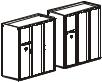
A Module is an independent Computer Room Air Conditioner (CRAC) that operates based on its own temperature and humidity sensors.
System
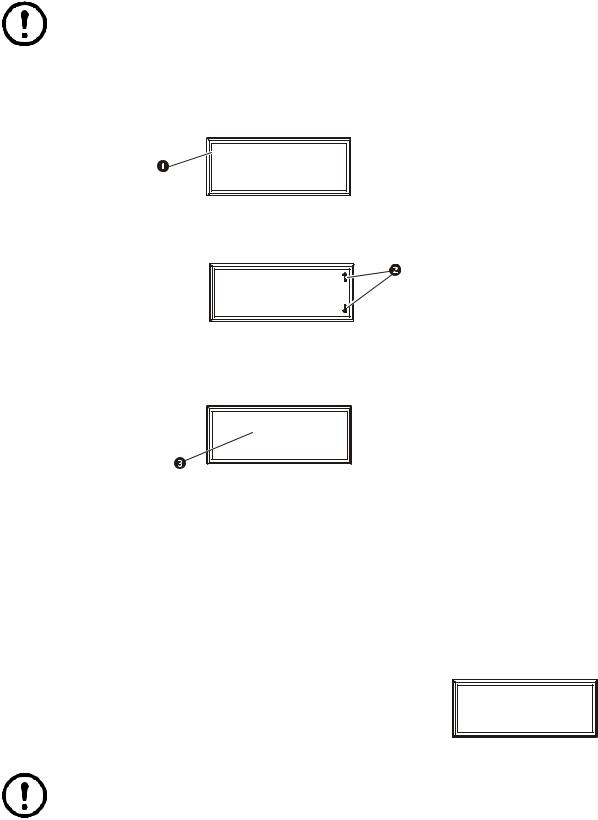
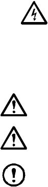
 na0267a
A System is a set of one to three Modules or CRACs. System operation is based on an average of the combined temperature and humidity sensors of all the Modules in the System. The Modules in a System work together as a single unit to increase cooling capacity.
Main Module
Expansion Module 1
 na0269a
Expansion Module 2
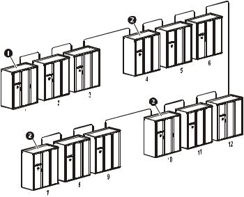
In a System, one of the Modules is designated as the Main Module and the rest of modules are designated as Expansion Modules. The Main Module is the controller for all the Modules in the System. It contains the Programmable Customer Input/Output Module (PCIOM) boards, the webcard, and establishes communications with the Building Management System (BMS).
Note: When using the System configuration, only the Main Module display will be operational. The Expansion Module displays will not operate.
NetworkAIR FM DX 60 Hz Operation, Maintenance, and Troubleshooting |
1 |
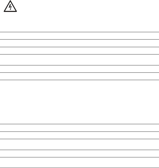
Group
A Group is a set of two, three or four Systems that work together to provide redundancy and load sharing capabilities.
To enable the Modules to work in a System or Group, the only requirement is to connect them together with a CAT 5 cable terminated with RJ-45 connectors and to set the DIP switches on the controller board of each module to assign the Main Module, the Expansion Modules, and the System number.
Main Module
Expansion Modules
System 2
System 1
na0270a
System 4
System 3
2 |
NetworkAIR FM DX 60 Hz Operation, Maintenance, and Troubleshooting |
Safety
Symbols Used in this Manual
Save these instructions
This manual contains important instructions that must be followed when servicing this equipment.
Safety symbols that may be used in this manual
Electrical Hazard: Indicates an electrical hazard which, if not avoided, could result in injury or death.
Danger: Indicates a hazard which, if not avoided, could result in severe personal injury or death.
Warning: Indicates a hazard which, if not avoided, could result in personal injury or damage to product or other property.
Heavy: Indicates a heavy load that should not be lifted without assistance.
Caution: Indicates a potential hazard which, if not avoided, could result in damage to the equipment or other property.
Tip Hazard: This equipment is easily tipped. Use extreme caution when unpacking or moving.
Note: Indicates important information.
Cross-reference symbols used in this manual
Indicates that more information is available in another location.
NetworkAIR FM DX 60 Hz Operation, Maintenance, and Troubleshooting |
3 |

Safety Hazards
Lockout/tagout
Warning: Make sure to follow the lockout/tagout procedures for your site to remove access to a device and physically label the device as intentionally out of service while servicing this equipment.
Electrical hazards
Electrical Hazard: Unless otherwise indicated, remove power before attempting to service this unit. Remove power at the upstream breaker and disconnect the power cords before servicing. Failure to do so could result in serious injury or death.
Electrical Hazard: Follow all local and national electrical codes when installing or servicing a NetworkAIR FM.
Static discharge
Static Discharge: Circuit boards contained within the unit are sensitive to static electricity. Whenever possible, touch only the end-plates and use one or more of these electrostatic-discharge devices (ESDs) while handling the boards: wrist straps, heel straps, toe straps, or conductive shoes. Failure to do so may cause damage to the board and improper operation of the unit.
Safe refrigerant handling
Note: Service to components in the refrigeration loop should be performed only by a certified HVAC technician.
Note: Follow all local and national regulations when handling refrigerants.
Caution: Use applicable safety precautions when working with pressurized systems. Some piping in this unit contains refrigerant that is under pressure. Use care when working with piping or pipe fittings.
Moving parts
Warning: This equipment contains moving parts such as fans. Use care around components that are behind air blocks or separated by doors or access panels.
Tools and parts
Caution: Ensure that all spare parts and tools are removed from the equipment before operation.
4 |
NetworkAIR FM DX 60 Hz Operation, Maintenance, and Troubleshooting |
Operation
Display Interface
Status |
ESC |
|
Check |
|
|
Log |
? |
|
Minor |
||
|
||
Alarm |
|
|
Major |
|
|
Alarm |
|
na0262a
Item |
Function |
|
|
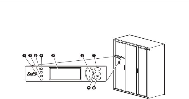
Major Alarm LED |
When lit, a major alarm condition exists. |
|
|
Minor Alarm LED |
When lit, a minor alarm condition exists. |
|
|
Check Log LED |
When lit, at least one new major alarm or minor alarm |
|
or event has occurred. |
|
|
Status LED |
When lit, the Module is on. |
|
|
Liquid Crystal Display (LCD) |
View alarms, status data, instructional help, and |
|
configuration items. |
|
|
Up and down arrow keys |
Select menu items and access information. |
|
|
ESC key |
Return to previous screen. |
|
|
ENTER key |
Open menu items and input changes to Module, |
|
System, and Group settings. |
|
|
HELP key |
Display context-sensitive help. Press the HELP key |
|
for information about each option on the screen and |
|
for instructions on how to perform tasks. |
NetworkAIR FM DX 60 Hz Operation, Maintenance, and Troubleshooting |
5 |
Using the Display Interface
Scrolling status screens
The first time you apply power to the Module, the display initializes and runs an LED and alarmtone test.
After start-up, the interface displays the firmware revision number (if the fast start-up is disabled). The display interface then scrolls automatically and continuously through the following nine screens of status information.
Status Screen Name |
Status Information Displayed |
|
|
Control Temp & Humidity |
• Temperature and humidity at the sensors being used to control the |
|
environment |
|
• Remote Temperature and Humidity (optional) |
|
• Humidity Control Method (dew point or relative humidity) |
|
|
Cool/Dehum Demands |
• Cool Demand % |
|
• Dehumidify Demand % |
|
• Actual Output % |
|
|
Reheat Demand |
• Reheat Demand % |
|
(Electric SCR only) |
|
|
Humidify Demand |
• Humidify Demand % |
|
• Humidify Actual % |
|
|
Group Status |
• Number of Systems |
|
• Setpoint Share: On/Off |
|
• Demand Fighting: On/Off |
|
|
Group Status |
• System number |
|
• Role |
|
• State |
|
|
Active Alarms |
• Alarm number |
|
• Module identifier |
|
• Alarm name |
|
• Time stamp |
|
|
Setpoints |
• Cool °C (or °F) |
|
• Reheat °C (or °F) |
|
|
Setpoints |
• Dehumidify % RH |
|
• Humidify % RH |
|
|
Press the up or down arrow key to interrupt the automatic scrolling and view a specific status screen. To return to the scrolling status screens, press the ESC key from the main menu screen.
6 |
NetworkAIR FM DX 60 Hz Operation, Maintenance, and Troubleshooting |
Main menu screen
On any top-level status screen, press the ENTER or ESC key to open the main menu screen.
Note: If the display interface is inactive for ten minutes (the default delay), it will return to the scrolling status screens. To change this delay, use the Time-out setting under the Password menu.
Navigating the interface
Selector arrows. Press the up or down arrow key to move the selector arrow to a menu option or setting. Press the ENTER key to view the selected screen or modify the setting.

 Date: 18-Jun-2007
Time: 13:15:23
na0158a
Continue arrows. Continue arrows indicate that additional options or settings are available on a menu or status screen. Press the up or down arrow key to view the additional items.

 Date: 18-Jun-2007
Time: 13:15:23
na0281a
Input arrows. Input arrows next to a selected setting indicate that the setting can be modified by pressing the up or down arrow key. Press the ENTER key to save the change or the ESC key to cancel the change.
Date: 18-Jun-2007
Time: 13:15:23
na0254a
Password entry
The Module has two levels of password protection:
•User password for users who need to change basic and environmental settings
•Service password for users who need to change advanced options or modify settings that control the components in the Module
When you try to change any of the settings, the display prompts you to enter your password.
The default value for both the User and Service password is APC (upper case). To enter your password, use the up or down arrow keys to scroll through the alphabet. At the desired letter, press the ENTER key to select the letter and move the cursor to the next letter position. After selecting the last letter of your password, press the ENTER key once more to submit your password.
Service Password:
********
User Password:
APC*****
na0436a
Note: Passwords are case-sensitive.
NetworkAIR FM DX 60 Hz Operation, Maintenance, and Troubleshooting |
7 |

Start the System
Path: Main Menu > On/Off
To start the System, select the On/Off option on the main menu and change the setting to On. The System will run according to the current settings under Control Environment.
Change settings
To change a setting, use the up or down arrow keys to move the selector arrow to the setting, and press the ENTER key.
List of choices. If the setting is a list of choices, an input arrow is displayed next to the setting. Press the up or down arrow key to make your selection. Press the ENTER key to save the setting and exit from input mode. Press the ESC key to exit without saving.
Numbers or text fields. If the setting is a number or text field, use the arrow keys to select the value for the first character, and press the ENTER key to move to the next character position. Repeat this procedure to select and set each character. After the last character is set, press the ENTER key to save the setting and exit from input mode. Press the ESC key to exit without saving.
Stop the System
Path: Main Menu > On/Off
To stop the System, select the On/Off option on the main menu and change the setting to Off.
Note: Change the setting to Off to shut down all modes of operation and the blower fan; the display interface and the controller will continue to receive power.
For Systems with electric reheat, the blower fans may continue to operate for up to 60 seconds to purge heat from the System.
Factory default settings
All Module settings are controlled through the display interface on the front of the Main Module for each System. The factory default temperature is set at 22.2°C (72°F ) in the cooling mode, and 20°C (68°F ) in the reheat mode. The default deadband is set at 1.1°C (2°F).
8 |
NetworkAIR FM DX 60 Hz Operation, Maintenance, and Troubleshooting |
Commissioning
After installation, verify that all components are working properly and that the Module is ready to begin operation. Before you commission the Module, make sure that the following inspections are completed:
•Initial
•Electrical
•Mechanical
•User interface
After these inspections are complete, the Module is ready for the functional test and charging. Complete the following procedures to begin operation of the Module:
•Functional test
•Module charging
After you complete the following two checklists, the Module is ready to begin normal operation:
•Start-up
•Final
Electrical Hazard: Perform Lockout/Tagout procedures on the equipment being serviced. Failure to remove power before servicing this equipment could result in serious injury or death.
The initial inspection ensures that the Module has been securely mounted to the floor stand or sub-base and that the air distribution system is properly installed. The room must be sealed with a vapor barrier and the Module must be free of damage.
 To perform the inspection, see “Initial Inspection Checklist” on page 11.
Caution: Do not run service utilities in front of the blower outlets.
Caution: The vapor barrier minimizes moisture infiltration. Without a vapor barrier, your equipment will have difficulty maintaining the humidity in the room.
Do not introduce unconditioned outside air into the space.
Note: 914 mm (36 in ) of clear floor space in front of the equipment is required for service access.
Electrical inspection. The electrical inspection verifies that all electrical connections are secure and correct and that the Module is properly grounded.
NetworkAIR FM DX 60 Hz Operation, Maintenance, and Troubleshooting |
9 |

Power On/Off Procedure
Power on
1.Turn utility power on.
2.Set each main breaker located behind the left door to the “1” (ON) position by pushing each breaker lever to the left.
Note: The main breakers may be in the trip position (visible yellow indication) due to a previous power off. Reset the breakers by pushing the levers first to the right (off) then to the left (on).
Note: Wait approximately 30 seconds for the system to start.
 See “Start the System” on page 8 for system startup procedure.
Note: If power is lost, the system will continue in the last selected mode when power returns. No action is required.
Power off
1. Stop the System.
 See “Stop the System” on page 8.
2.Push the red power interrupt button on the left front door.
3.Turn utility power off.
10 |
NetworkAIR FM DX 60 Hz Operation, Maintenance, and Troubleshooting |
Commissioning Checklists
Initial Inspection Checklist
Warning: Review the safety and data sheet (MSDS-Material Safety Data Sheet) for R-22 for safe handling of the refrigerant.
The equipment operates under pressure — 276-2930 kPa (40-425 psi ). Take proper safety precautions when connecting gauges or servicing the refrigerant/condenser loop or chilled water piping.
Never operate this equipment with any cover, guard, door, or panel removed unless instructions indicate otherwise and do so using extreme caution.
Electrical Hazard: Perform Lockout/Tagout procedures on the equipment being serviced. Failure to remove power before servicing this equipment could result in serious injury or death.
Caution: Do not run service utilities in front of the fan outlets.
Caution: The vapor barrier minimizes moisture infiltration. Without a vapor barrier, it will be difficult to maintain the humidity in the room.
Do not introduce unconditioned outside air into the space.
Ensure that:
The installation procedure is complete according to the installation manual.
Walls, floor, and ceiling are sealed with vapor barrier.
Raised floor space (downflow only) beneath the equipment is a minimum of 18 in (457 mm).
Optional floorstands are installed correctly and that the equipment is secured to them.
Duct work is properly installed.
The equipment shows no signs of damage.
Clearance around the system is in accordance with ASHRAE, local and national codes and the installation manual.
Shipped components (leak detection devices, firestats, smoke detectors, remote sensors, etc.) are installed securely.
Any optional remote temperature and humidity probes installed are supported by the NetworkAIR FM DX.
NetworkAIR FM DX 60 Hz Operation, Maintenance, and Troubleshooting |
11 |
Electrical Inspection Checklist
Electrical Hazard: All electrical wiring must comply with national and local codes. The equipment must be grounded to an earth ground (do not use a water-pipe ground). Three-phase electrical service is required.
Ensure that:
Incoming voltages match the phase and voltage listing on the nameplate.
The equipment is properly grounded.
Internal electrical components and terminal blocks do not have any loose connections.
Electrical connections are tight, including: contactors, terminal blocks, circuit breakers, controllers, switches, relays, auxiliary devices, and field connections.
Circuit breakers are correct and securely attached to the DIN rail.
Interconnecting control wiring from the equipment to the outdoor heat exchanger/pump is correct.
Mechanical and Refrigeration Inspection Checklist
Ensure that:
Condenser fans and blowers are turning freely and that the blades are not distorted or bent.
Condensate drain line is at least the size of the drain connection.
Condensate drain line is pitched (10 mm/m, 1/8 in/foot minimum) and properly trapped (100-130 mm, 4-5 in).
Humidifier water-supply piping is connected and is the correct size.
Mechanical connections are tight, including compressor roto-lock connections and the receiver roto-lock connections. Also check that the humidifier cylinders are seated on the fill/drain block.
12 |
NetworkAIR FM DX 60 Hz Operation, Maintenance, and Troubleshooting |
Mechanical Inspection: Air-cooled Checklist
Warning: Air-cooled equipment is shipped from the factory with a nitrogen holding charge. Remove the nitrogen holding charge using the multiple Schrader valves located on the internal refrigerant piping.
Caution: Do not block air distribution (fan discharge openings) with field-installed piping. Failure to properly install piping and traps may result in improper operation and poor oil return through the refrigerant piping system.
Ensure that:
Refrigerant piping size is correct according to the line-size table in the installation manual.
Vertical, horizontal, and total run lengths are recorded for liquid and discharge lines .
Number of 45and 90-degree ells in the refrigerant piping are recorded.
Field-installed traps and piping are in accordance with the installation manual and follow proper piping practices.
Refrigerant piping is adequately supported and isolated when necessary.
Field-installed service valves are open.
Relief valves are installed in accordance with the installation manual.
Piping in the building and on the roof is properly insulated.
User Interface Box Inspection Checklist
Ensure that:
System CAN bus is connected to each System, Main Module, and Expansion Module.
OHE interlock is connected.
Input contacts and output relays are connected correctly.
Module CAN bus is connected to each PCIOM board.
Building management system RS-485 port is connected properly (if connecting to a building management system).
NetworkAIR FM DX 60 Hz Operation, Maintenance, and Troubleshooting |
13 |

Start-up Inspection Checklist
While the equipment is operating, ensure that:
The sight glass moisture sensor is green.
The current draw of all fan motors, heaters, compressors, humidifiers, transformers, and fans for each mode of operation (cool, reheat, dehumidify, humidify) are within the ratings of their circuit breaker.
1.Record the current at the main power connection of the main circuit breaker.
2.Record all current draws on the load side of any circuit breakers used for each device.
3.Compare the circuit breaker setting for each device to the actual current measured and the full load amps of the device to verify that the current draws are acceptable.
Compressor suction and discharge pressures are recorded.
Superheat and sub-cooling temperatures are recorded.
The equipment is free from malfunctions, including refrigeration leaks, unusual vibrations, or other irregularities in each mode of operation.
The low pressure switch is operating correctly.
1.Disconnect power to the liquid line solenoid at the wiring harness connector.
2.Record the low-pressure shutoff point with a manifold.
3.Reconnect the wiring harness to the solenoid.
The high-pressure switch is operating correctly.
1.Shut down the condenser.
2.The head-pressure will rise until the high-pressure switch shuts down the compressor.
3.Record the shutoff point.
4.Restore power to the condenser.
5.Manually reset the high head pressure switch.
The cool, reheat, dehumidification, and humidification cycles engage.
Filters are clean and free of debris.
The clogged filter alarm is operating properly.
1.Cover 2/3 of the filter area.
2.Check the display interface for a Filter Clogged alarm condition
Setpoints for the following are recorded:
•Condenser fan minimum starting pressure.
•Condenser fan speed control operating range.
14 |
NetworkAIR FM DX 60 Hz Operation, Maintenance, and Troubleshooting |

Final Inspection Checklist
Ensure that:
The system interior and exterior are clean and free from debris.
Installed options (smoke detectors, firestat, water detector, remote sensor, remote relay shutdown, dry contact alarm, essential/non-essential lockout, Redundant Unit Group control, condensate pump, etc.) are operating correctly.
Setpoints and deadbands are set.
Packaging materials are disposed of properly.
You have sent the start-up form to APC.
Owner Acceptance
To ensure proper unit operation and trouble free operation the following procedures must be completed and filed with the customer for future reference.
•Review installation of the equipment. Verify that installation is in compliance with Installation manual instructions/recommendations.
•Complete start-up checklist and file with owner and factory to activate warranty policy.
•Train personnel responsible for maintenance and minor adjustments to temperature & humidity set points.
•Recommend spare parts for the owner to keep on hand, especially for critical operation installations.
•Offer a list of contacts for service, technical assistance, replacement parts.
NetworkAIR FM DX 60 Hz Operation, Maintenance, and Troubleshooting |
15 |

System Configuration
The System configuration options are defined both at the factory and during the commissioning of the Modules in the System.
Caution: Changing the settings incorrectly can cause serious malfunctions and damage to your System. Only qualified service personnel should make changes to these settings.
Note: Some System configuration settings may not apply to your APC NetworkAIR FM DX Precision Air Conditioner.
System options
Path: Main > Setup > System # > System Config > System Options
The System Options menu contains settings that identify the hardware installed in this System and the methods used to control that hardware.
Mains In. Indicates the primary operating voltage required for this System. The configuration is based on the voltage of the electrical components in the System and is printed on the nameplate attached to the door on the right side of the electrical box.
Coil Cfg. Indicates the coil configuration installed in the Modules of this System.
•DX—Direct expansion (DX) coil
•Econ—Economizer and DX coils
•MultiCool—MultiCool® (chilled water) and DX coils
16 |
NetworkAIR FM DX 60 Hz Operation, Maintenance, and Troubleshooting |

Humid Ctrl. Indicates the humidity control method. The System can control the humidity based on the relative humidity (RH) of the return air and the dew point (DewPt) of the return air.
•Relative humidity (RH): The System activates humidification modes based on the difference between the humidify/dehumidify setpoint and the return humidity value.
•Dew point (DewPt): The dew point method corrects for hotspots near the environmental sensors, and is calculated from the temperature and relative humidity of the room air.
–The System activates humidification based on the dew point setpoint and the calculated dew point in the room.
–The dew point setpoint is calculated from the humidification setpoint and the reheat setpoint. If there is no reheat mode, then the cooling setpoint is used.
Example. If the reheat setpoint is 20°C (68°F) and the humidification setpoint is 50%, the dew point setpoint is 27°C (80°F). If the room temperature is 23°C (74°F) and the return humidity is 40% the dew point of the room is 26°C (78°F).
The humidifier demand is calculated as the difference between the actual room dew point and the desired room dew point divided by the sensitivity.
In this example: Demand = (49 - 48) / 2 = 0.5 or 50% demand. The humidifier output will be about 50%.
Note: The System will always use the dew point method when the remote sensor readings are used to control the room environment or if the System is part of a redundant Group.
NetworkAIR FM DX 60 Hz Operation, Maintenance, and Troubleshooting |
17 |

# PCIOMs. Set the number of Programmable Customer Input/Output Modules (PCIOMs) installed in the user interface box. This setting controls the number of input contacts and output relays available in the Input/Output menu.
See “Contacts and Relays” on page 25 to set up the contacts and relays from the display interface.
See the NetworkAIR FM DX 60 Hz Installation manual to connect the contacts and relays to the Main Module.
# Modules in Sys. Indicates the number of Modules in this System. Up to three Modules can be joined together to work as a single System.
Air Filter. Set the type of air filters installed in the Modules of this System to either standard (3040%) or high efficiency (65-85%).
Fast Startup. Set the System to bypass the normal start-up sequence and start-up delay the next time power is applied to the System.
Note: The Fast Startup option is not recommended for typical installations.
Airflow. Set the airflow pattern for the Modules in this System.
•Up
•Down
Rej. Method. Indicates the method used for heat rejection by the refrigeration system.
•Air
•Water
•Glycol
Dehum Capacity. The dehumidify mode can be set to use half capacity or full capacity of the cooling coil.
•Half capacity uses one compressor and half of the cooling coil to dehumidify. Rooms with small heat loads should use half capacity to avoid over-cooling while dehumidifying.
•Full capacity uses the entire coil and both compressors.
When the unit is in dehumidification mode the dehumidification solenoid valve on the secondary liquid line is not energized and remains closed. All refrigerant is directed through the expansion valve which feeds three quarters of the cooling coil.
Module Rot. The System rotates the order in which the compressors are engaged to equalize the total number of hours that each compressor runs. Set the number of hours at which to change the order in which the compressors are engaged. A setting of zero indicates that the order in which the compressors are engaged should not be changed.
Refrigerant. Set to the type of refrigerant charge used in the direct expansion refrigeration system..
Suction Pressure Compensation. Allows the System to slow the blowers if the suction pressure gets too high. Use this setting if you are using the FM in a high-density application.
18 |
NetworkAIR FM DX 60 Hz Operation, Maintenance, and Troubleshooting |

System delays
Path: Main > Setup > System # > System Config > System Delays
The System Delays protect the Modules in the System from excessive wear and damage and keep the modes (cooling, reheat, and dehumidify) from working against each other.
Comp Min ON. The delay begins when the compressor engages and then prevents the compressor from disengaging until the delay has expired. It protects the compressors from rapidly cycling between on and off and pushing all of their lubricating oil out into the refrigerant line.
Caution: Reducing the Comp Min ON delay can shorten the compressor life by causing excessive wear and damage.
Comp Min OFF. The delay begins when the compressor disengages and then prevents the compressor from engaging until the delay has expired. It protects the compressors from rapidly cycling between on and off and pushing all of their lubricating oil out into the refrigerant line.
Caution: Reducing the Comp Min OFFdelay can shorten the compressor life by causing excessive wear and damage.
Cndsr Vlv Dly. The condenser fluid valve close delay begins when the compressors disengage, and then keeps coolant flowing through the heat exchanger until the delay expires. Once the delay expires, the condenser fluid valve closes.
Intrstg Dly. The interstage delay begins when the first compressor (stage 1) in a Module engages. It prevents a second compressor (stage 2) in a System from engaging until the delay has expired.
Start-up Dly. The start-up delay begins when the System is started and initialized. The System cannot begin operation until this delay has expired. Use the start-up delay to restart equipment sequentially in your room after a power loss.
Mode Dly. The start-up delay begins when the blowers start. It allows the sensors to obtain an accurate reading of the room conditions and it allows the System to check for major alarms before engaging environmental control functions.
Communication Loss Shutdown Delay. Set the communication loss shutdown delay. The delay begins when an Expansion Module loses communication with the Main Module of a System. If communication is not restored before the delay expires, the Expansion Module will shut down. Set the delay for up to twenty-four hours, or set the Expansion Modules to continue operating if communication with the Main Module is lost by selecting Disabled.
NetworkAIR FM DX 60 Hz Operation, Maintenance, and Troubleshooting |
19 |
Loading...