


 Loading...
NetworkAIR™ IR Precision
Air Conditioner
In-row
Operation, Maintenance, and
Troubleshooting

Contents
Operation ................................................................ |
1 |
Display Interface . . . . . . . . . . . . . . . . . . . . . . . . . . . . . . . . . . . . 1
Using the Display . . . . . . . . . . . . . . . . . . . . . . . . . . . . . . . . . . . 2
Scrolling status screens . . . . . . . . . . . . . . . . . . . . . . . . . . . . 2
Main menu screen . . . . . . . . . . . . . . . . . . . . . . . . . . . . . . . 3
Navigating the interface . . . . . . . . . . . . . . . . . . . . . . . . . . . 3
Password entry . . . . . . . . . . . . . . . . . . . . . . . . . . . . . . . . . 4
Start the System . . . . . . . . . . . . . . . . . . . . . . . . . . . . . . . . 4
Change settings . . . . . . . . . . . . . . . . . . . . . . . . . . . . . . . . 4
Stop the System . . . . . . . . . . . . . . . . . . . . . . . . . . . . . . . . 5
Set Up System Configuration . . . . . . . . . . . . . . . . . . . . . . . . . . . 6
System Options . . . . . . . . . . . . . . . . . . . . . . . . . . . . . . . . . 6
System Delays . . . . . . . . . . . . . . . . . . . . . . . . . . . . . . . . . . 8
Building management . . . . . . . . . . . . . . . . . . . . . . . . . . . . 9
Sensor setup . . . . . . . . . . . . . . . . . . . . . . . . . . . . . . . . . . . 9
Options for Fluid-Cooled Modules . . . . . . . . . . . . . . . . . . . . . . 10
Valve Types . . . . . . . . . . . . . . . . . . . . . . . . . . . . . . . . . . 11
Actuator Types . . . . . . . . . . . . . . . . . . . . . . . . . . . . . . . . 11
Coil Fluid Temp Activation Threshold and Deadband . . . . . . . 12
Set Up Contacts and Relays . . . . . . . . . . . . . . . . . . . . . . . . . . . 13
Input contacts . . . . . . . . . . . . . . . . . . . . . . . . . . . . . . . . . 13
Output relays . . . . . . . . . . . . . . . . . . . . . . . . . . . . . . . . . 14
Set Up Module Configuration . . . . . . . . . . . . . . . . . . . . . . . . . 16
Configure Module . . . . . . . . . . . . . . . . . . . . . . . . . . . . . . 16
Alarm detectors . . . . . . . . . . . . . . . . . . . . . . . . . . . . . . . . 16
NetworkAIR IR Operation, Maintenance, and Troubleshooting |
i |
Set Up Module Control. . . . . . . . . . . . . . . . . . . . . . . . . . . . . . . 17
Calibrate airflow manually . . . . . . . . . . . . . . . . . . . . . . . . 17
Calibrate airflow automatically . . . . . . . . . . . . . . . . . . . . . 17
Reset variable frequency drive . . . . . . . . . . . . . . . . . . . . . . 18
Reset humidifier . . . . . . . . . . . . . . . . . . . . . . . . . . . . . . . 18
Set up Humidifier . . . . . . . . . . . . . . . . . . . . . . . . . . . . . . 18
Reset compressors . . . . . . . . . . . . . . . . . . . . . . . . . . . . . . 19
Control the Environment . . . . . . . . . . . . . . . . . . . . . . . . . . . . . 20
How the modes work . . . . . . . . . . . . . . . . . . . . . . . . . . . 20
Setpoints . . . . . . . . . . . . . . . . . . . . . . . . . . . . . . . . . . . . 21
Deadbands . . . . . . . . . . . . . . . . . . . . . . . . . . . . . . . . . . 22
Modes . . . . . . . . . . . . . . . . . . . . . . . . . . . . . . . . . . . . . . 22
Essential Functions . . . . . . . . . . . . . . . . . . . . . . . . . . . . . 22
PID controls . . . . . . . . . . . . . . . . . . . . . . . . . . . . . . . . . . 23
How to tune the PIDs . . . . . . . . . . . . . . . . . . . . . . . . . . . 24
Humidification sensitivity . . . . . . . . . . . . . . . . . . . . . . . . . 25
Set Up Alarms . . . . . . . . . . . . . . . . . . . . . . . . . . . . . . . . . . . . . 26
Temperature alarms . . . . . . . . . . . . . . . . . . . . . . . . . . . . . 26
Humidity alarms . . . . . . . . . . . . . . . . . . . . . . . . . . . . . . . 26
Maint intervals . . . . . . . . . . . . . . . . . . . . . . . . . . . . . . . . 27
Alarm delay . . . . . . . . . . . . . . . . . . . . . . . . . . . . . . . . . . 27
Coil fluid thresholds . . . . . . . . . . . . . . . . . . . . . . . . . . . . 27
Set Up Group. . . . . . . . . . . . . . . . . . . . . . . . . . . . . . . . . . . . . . 28
Group config . . . . . . . . . . . . . . . . . . . . . . . . . . . . . . . . . 28
Group settings . . . . . . . . . . . . . . . . . . . . . . . . . . . . . . . . 29
Sys failure events . . . . . . . . . . . . . . . . . . . . . . . . . . . . . . 29
Set Up the Display . . . . . . . . . . . . . . . . . . . . . . . . . . . . . . . . . . 31
Password & Time-out . . . . . . . . . . . . . . . . . . . . . . . . . . . . 31
Date and time . . . . . . . . . . . . . . . . . . . . . . . . . . . . . . . . 31
Temperature & pressure units . . . . . . . . . . . . . . . . . . . . . . 31
Adjust display . . . . . . . . . . . . . . . . . . . . . . . . . . . . . . . . . 32
How to update the firmware . . . . . . . . . . . . . . . . . . . . . . . 32
Reset to defaults . . . . . . . . . . . . . . . . . . . . . . . . . . . . . . . 33
Product data . . . . . . . . . . . . . . . . . . . . . . . . . . . . . . . . . 33
Set Up Network Configuration . . . . . . . . . . . . . . . . . . . . . . . . . 34
Network config . . . . . . . . . . . . . . . . . . . . . . . . . . . . . . . . 34
ii |
NetworkAIR IR Operation, Maintenance, and Troubleshooting |
View Status Readings . . . . . . . . . . . . . . . . . . . . . . . . . . . . . . . 35
Scrolling status screens . . . . . . . . . . . . . . . . . . . . . . . . . . . 35
Module status . . . . . . . . . . . . . . . . . . . . . . . . . . . . . . . . . 35
System status . . . . . . . . . . . . . . . . . . . . . . . . . . . . . . . . . 36
Group status . . . . . . . . . . . . . . . . . . . . . . . . . . . . . . . . . . 37
View Event Log . . . . . . . . . . . . . . . . . . . . . . . . . . . . . . . . 37
View Log . . . . . . . . . . . . . . . . . . . . . . . . . . . . . . . . . . . . 37
Respond to Alarms . . . . . . . . . . . . . . . . . . . . . . . . . . . . . . . . . 38
Major or minor alarm LEDs . . . . . . . . . . . . . . . . . . . . . . . . 38
Control beeper . . . . . . . . . . . . . . . . . . . . . . . . . . . . . . . . 38
View active alarms . . . . . . . . . . . . . . . . . . . . . . . . . . . . . . 38
Clear active alarms . . . . . . . . . . . . . . . . . . . . . . . . . . . . . . 39
Reset sys failure . . . . . . . . . . . . . . . . . . . . . . . . . . . . . . . 39
Alarm messages and suggested actions . . . . . . . . . . . . . . . . 40
Network Management Card |
...................................47 |
Quick Configuration . . . . . . . . . . . . . . . . . . . . . . . . . . . . . . . . |
47 |
Overview . . . . . . . . . . . . . . . . . . . . . . . . . . . . . . . . . . . . 47
TCP/IP configuration methods . . . . . . . . . . . . . . . . . . . . . . 48
APC Device IP Configuration Wizard . . . . . . . . . . . . . . . . . . 48
BOOTP & DHCP configuration . . . . . . . . . . . . . . . . . . . . . . 48
Local access to the control console . . . . . . . . . . . . . . . . . . . 51
Remote access to the control console . . . . . . . . . . . . . . . . . 52
Control console . . . . . . . . . . . . . . . . . . . . . . . . . . . . . . . . 52
How to Access a Configured Unit . . . . . . . . . . . . . . . . . . . . . . 54
Overview . . . . . . . . . . . . . . . . . . . . . . . . . . . . . . . . . . . . 54
Web interface . . . . . . . . . . . . . . . . . . . . . . . . . . . . . . . . . 54
Telnet/SSH . . . . . . . . . . . . . . . . . . . . . . . . . . . . . . . . . . . 54
SNMP . . . . . . . . . . . . . . . . . . . . . . . . . . . . . . . . . . . . . . 55
FTP/SCP . . . . . . . . . . . . . . . . . . . . . . . . . . . . . . . . . . . . . 56
How to Recover From a Lost Password . . . . . . . . . . . . . . . . . . 57 How to Upgrade Firmware . . . . . . . . . . . . . . . . . . . . . . . . . . . 58
NetworkAIR IR Operation, Maintenance, and Troubleshooting |
iii |
Maintenance ......................................................... |
61 |
Monthly Preventive Maintenance . . . . . . . . . . . . . . . . . . . . . . . 61
Environment . . . . . . . . . . . . . . . . . . . . . . . . . . . . . . . . . 61
Cleanliness . . . . . . . . . . . . . . . . . . . . . . . . . . . . . . . . . . . 62
Mechanical . . . . . . . . . . . . . . . . . . . . . . . . . . . . . . . . . . 62
Electrical . . . . . . . . . . . . . . . . . . . . . . . . . . . . . . . . . . . . 62
Quarterly Preventive Maintenance . . . . . . . . . . . . . . . . . . . . . . 63
Mechanical . . . . . . . . . . . . . . . . . . . . . . . . . . . . . . . . . . 63
Electrical . . . . . . . . . . . . . . . . . . . . . . . . . . . . . . . . . . . . 63
Functional tests . . . . . . . . . . . . . . . . . . . . . . . . . . . . . . . 64
Semi-Annual Preventive Maintenance. . . . . . . . . . . . . . . . . . . . 65
Cleanliness . . . . . . . . . . . . . . . . . . . . . . . . . . . . . . . . . . . |
65 |
Electrical . . . . . . . . . . . . . . . . . . . . . . . . . . . . . . . . . . . . |
65 |
Functional tests . . . . . . . . . . . . . . . . . . . . . . . . . . . . . . . |
65 |
Troubleshooting .................................................... |
67 |
Warranty............................................................... |
71 |
Limited Product Warranty for APC Products . . . . . . . . |
. . . . . . . 71 |
APC product covered . . . . . . . . . . . . . . . . . . . . . . . . . . . . |
71 |
Terms of warranty . . . . . . . . . . . . . . . . . . . . . . . . . . . . . . |
71 |
Non-transferable Warranty extends to first purchaser for use . 71 |
|
Assignment of warranties . . . . . . . . . . . . . . . . . . . . . . . . . |
72 |
Drawings, descriptions . . . . . . . . . . . . . . . . . . . . . . . . . . . |
72 |
Exclusions . . . . . . . . . . . . . . . . . . . . . . . . . . . . . . . . . . . |
72 |
Warranty Procedures . . . . . . . . . . . . . . . . . . . . . . . . . |
. . . . . . . 74 |
Claims . . . . . . . . . . . . . . . . . . . . . . . . . . . . . . . . . . . . . . |
74 |
Labor . . . . . . . . . . . . . . . . . . . . . . . . . . . . . . . . . . . . . . |
74 |
Parts . . . . . . . . . . . . . . . . . . . . . . . . . . . . . . . . . . . . . . . |
75 |
iv |
NetworkAIR IR Operation, Maintenance, and Troubleshooting |
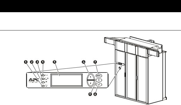
Operation
Display Interface
Item |
Function |
|
|
! Major Alarm LED |
When red, a major alarm condition exists. |
|
|
" Minor Alarm LED |
When yellow, a minor alarm condition exists. |
|
|
# Check Log LED |
When yellow, at least one new major alarm, minor |
|
alarm, or event has occurred. |
|
|
$ Status LED |
When green, the Module is on. |
|
|
% Liquid Crystal Display (LCD) |
View alarms, status data, instructional help, and |
|
configuration items. |
|
|
& Up and down arrow keys |
Select menu items and access information. |
|
|
' ESC key |
Return to previous screen. |
|
|
( ENTER key |
Open menu items and input changes to System and |
|
Module settings. |
|
|
) HELP key |
Display context-sensitive help. Press the HELP key for |
|
information about each option on the screen and for |
|
instructions on how to perform tasks. |
|
|
NetworkAIR IR Operation, Maintenance, and Troubleshooting |
1 |

Using the Display
The first time you apply power to the NetworkAIR IR In-row Precision Air Conditioner the display initializes and runs an LED and alarm-tone test.
Scrolling status screens
After start-up, the interface displays the firmware revision number (if the fast start-up is disabled). The display interface then scrolls automatically and continuously through nine screens of status information.
Status Screen Name |
Status Information Displayed |
|
|
Control Temp & Humidity |
• Temperature and Humidity at the sensors being used to control |
|
the environment |
|
• Remote Temperature and Humidity (optional) |
|
• Humidity Control Method (dew point or relative humidity) |
|
|
Cool/Dehum Demands |
• Cool Demand % |
|
Note: If you have more than one cooling coil (i.e., DX and |
|
MultiCool), the demands are distributed between them. |
|
• Dehumidify Demand % |
|
• Actual Output % |
|
|
Reheat Demand |
• Reheat Status: On/Off |
|
(Steam, hot water, or hot gas only) |
|
• Reheat Demand % |
|
(Electric SCR only) |
|
|
Humidify Demand |
• Humidify Demand % |
|
• Humidify Actual % |
|
|
Group Status |
• Number of Systems |
|
• Setpoint Share: On/Off |
|
• Demand Fighting: On/Off |
|
|
Group Status |
• System number |
|
• Role |
|
• State |
|
|
Active Alarms |
• Alarm number |
|
• Module identifier |
|
• Alarm name |
|
• Time stamp |
|
|
Setpoints |
• Cool °C (or °F) |
|
• Reheat °C (or °F) |
|
|
Setpoints |
• Dehumidify % RH |
|
• Humidify % RH |
|
|
Press the up or down arrow key to interrupt the automatic scrolling and view a specific status screen. To return to the scrolling status screens, press the ESC key from the main menu screen.
2 |
NetworkAIR IR Operation, Maintenance, and Troubleshooting |
Operation: Using the Display
Main menu screen
On any top-level status screen, press the ENTER or ESC key to open the main menu screen.
If the display interface is inactive for ten minutes (the default delay), it returns to the scrolling status screens. To change this delay, use the time-
out setting under the Password menu.
Note
Navigating the interface
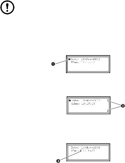
Selector arrows. Press the up or down arrow key to move the selector arrow ! to a menu option or setting. Press the ENTER key to view the selected screen or modify the setting.
Continue arrows. Continue arrows " indicate that additional options or settings are available on a menu or status screen. Press the up or down arrow key to view the additional items.
Input arrows. Input arrows # next to a selected setting indicate that the setting can be modified by pressing the up or down arrow key. Press the ENTER key to save the change or the ESC key to cancel the change.
NetworkAIR IR Operation, Maintenance, and Troubleshooting |
3 |
Operation: Using the Display
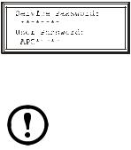
Password entry
The Module has two levels of password protection:
•User password for users who need to change basic and environmental settings
•Service password for users who need to modify settings that control the components in the Module or change advanced options
When you try to change any of the settings, the display prompts you to enter your password.
The default value for both the User and Service password is APC (upper case). To enter your password, use the up or down arrow keys to scroll through the alphabet. Press the ENTER key to select the current letter, and move the cursor to the next letter position. After selecting the last letter of your password, press the ENTER key once more to submit your password.
Passwords are case-sensitive.
Note
Start the System
Path: Main Menu > On/Off
To start the System, select the On/Off option on the main menu, and change the setting to On. The System will run according to the current settings under Control Environment.
Change settings
Use the up or down arrow key to move the selector arrow to the setting that you wish to change, and press the ENTER key.
•List of choices. If the setting is a list of choices, an input arrow is displayed next to the setting. Press the up or down arrow key to select the choice you want, and then press the ENTER key to exit the input mode and save the setting. Press the ESC key to exit without saving.
•Numbers or text fields. If the setting is a number or text field, use the arrow keys to select the value of the first character and press the ENTER key to move to the next. Press the ENTER key after the last character is set to exit the input mode and save the setting. Press the ESC key to exit without saving.
4 |
NetworkAIR IR Operation, Maintenance, and Troubleshooting |
Operation: Using the Display
Stop the System
Path: Main Menu > On/Off
To stop the System, select the On/Off option on the main menu and change the setting to Off.
Change the setting to Off to shut down all modes of operation and the blower fan; the display and the controller continue to receive power.
Note For Systems with electric reheat, the blower fans may continue to operate for up to 60 seconds to purge heat from the System.
NetworkAIR IR Operation, Maintenance, and Troubleshooting |
5 |

Set Up System Configuration
The System configuration options are set at the factory and may be modified during the commissioning of the Modules in the System.
Changing the settings incorrectly can cause serious malfunctions and damage to your System. Only qualified service personnel should make changes to these settings.
Not all the System configuration settings apply to the NetworkAIR IR In-row Precision Air Conditioner.
Note
System Options
Path: Main > Setup > System # > System Config > System Options
The System Options menu contains settings that identify the hardware installed in this System and the methods used to control that hardware.
Mains In. Indicate the primary operating voltage required for this System. The configuration is based on the voltage of the electrical components in the System, and is printed on the nameplate attached to the door on the left side of the electrical box.
UPS In. Indicate the operating voltage rating for the back-up power supply. The configuration is based on the voltage of the electrical components in the System, and is printed on the nameplate attached to the door on the left side of the electrical box.
Coil Cfg. Indicate the coil configuration installed in the Modules of this System. Available coil configurations include:
•Chilled liquid only — Chilled water coil only
•DX — Direct expansion (DX) coil
•Econ — Economizer and DX coils
•MultiCool — MultiCool (chilled water) and DX coils
Humid Ctrl. Indicate the humidity control method. The System can control the humidity based on the following:
•Relative humidity (RH) of the return air.
•Dew point (DewPt) of the return air. The dew point method corrects for hotspots near the environmental sensors.
The System will always use the dew point method, regardless of this setting:
• When using the remote sensor readings to control the room environment
• When the System is part of a redundant Group.
Note
6 |
NetworkAIR IR Operation, Maintenance, and Troubleshooting |

Operation: Set Up System Configuration
# PCIOMs. Set the number of Programmable Customer Input/Output Modules (PCIOMs) installed in the user interface box. This setting controls the number of input contacts and output relays available in the Input/Output menu.
See “Set Up Contacts and Relays” on page 13 to set up the contacts and relays from the display interface.
See the Installation Manual to connect the contacts and relays to the Main Module.
# Modules in Sys. Indicate the number of Modules in this System. Up to three Modules can be joined together to form a single System.
Air Filter. Set the type of air filters installed in the Modules of this System to either standard or high efficiency.
Fast Startup. Set the System to bypass the normal start-up sequence and delay the next time power is applied to the System.
Fast Startup is not recommended for typical installations.
Note
Airflow. Set the airflow pattern for the Modules in this System:
•Up
•Down
•Horizontal
Dehum Capacity. The Dehum Capacity setting does not apply to Systems without compressors. For Systems with compressors (direct expansion), the dehumidify mode can be set to use half capacity or full capacity of the cooling coil.
•Half capacity—uses one compressor and half of the cooling coil to dehumidify. Rooms with small heat loads should use half capacity to avoid over-cooling while dehumidifying.
•Full capacity—uses the entire coil and both compressors.
Module Rot. The Module Rot. setting does not apply to Systems without compressors. For Systems with compressors (direct expansion), the System rotates the order in which the compressors are engaged to equalize the total number of hours that each compressor runs. Set the number of hours at which to change the order in which the compressors are engaged. A setting of zero indicates that the order in which the compressors are engaged should not be changed.
Refrigerant. The Refrigerant setting applies only to Systems with compressors. Set the type of refrigerant charge used in the direct expansion refrigeration system.
NetworkAIR IR Operation, Maintenance, and Troubleshooting |
7 |

Operation: Set Up System Configuration
System Delays
Path: Main > Setup > System # > System Config > System Delays
The System delays protect the Modules in the System from excessive wear and damage, and keep the modes from working against each other.
Comp Min ON. The Comp Min ON setting does not apply to Systems without compressors. For Systems with compressors (direct expansion), the delay begins when the compressor engages, and then prevents the compressor from disengaging until the delay has expired. It protects the compressors from rapidly cycling between on and off and pushing all of their lubricating oil out into the refrigerant line.
Reducing the Comp Min ON delay can shorten the lives of your compressors by causing excessive wear and damage.
Comp Min OFF. The Comp Min OFF setting does not apply to Systems without compressors. For Systems with compressors (direct expansion), the delay begins when the compressor disengages, and then prevents the compressor from engaging until the delay has expired. It protects the compressors from rapidly cycling between on and off and pushing all of their lubricating oil out into the refrigerant line.
Reducing the Comp Min OFF delay can shorten the lives of your compressors by causing excessive wear and damage.
Cndsr Vlv Dly. The Cndsr Vlv Dly setting does not apply to Systems without compressors. For Systems with compressors (direct expansion), the "condenser fluid valve close delay" begins when the compressors disengage, and then keeps coolant flowing through the heat exchanger until the delay expires. Once the delay expires, the condenser fluid valve closes.
Intrstg Dly. The Intrstg Dly setting does not apply to Systems without compressors. For Systems with compressors (direct expansion), the interstage delay begins when the first compressor (stage 1) in a Module engages. It prevents a second compressor (stage 2) in a System from engaging until the delay has expired.
Start-up Dly. The Start-up Dly applies to all System configurations. The delay begins when the System is started and initialized. The System cannot begin operation until this delay has expired. Use the start-up delay to restart equipment sequentially in your room after a power loss.
Mode Dly. The Mode Dly setting applies to all System configurations. The delay begins when the blowers start. It allows the sensors to obtain an accurate reading of the room conditions, and the System to check for major alarms before engaging environmental control functions.
Communication Loss Shutdown Delay. The Comm Loss Shutdown Dly applies to MultiModule Systems. The delay begins when an Expansion Module loses communication with the Main Module of a System. If communication is not restored before the delay expires, the Expansion Module shuts down. Set the delay for up to twenty-four hours, or select Disabled to cause the Expansion Modules to remain operating if communication with the Main Module is lost.
8 |
NetworkAIR IR Operation, Maintenance, and Troubleshooting |

Operation: Set Up System Configuration
Building management
Path: Main > Setup > System # > System Config > Building Management
If you are using a building management system with your NetworkAIR IR In-row Precision Air Conditioner, you must set the following values:
Address. The address of the Main Module on the RS-485 bus for a building management system.
Baud Rate. The bus speed for the RS-485 bus.
Parity. The parity for the RS-485 bus.
Stop Bits. The stop bits for the RS-485 bus.
See the Installation Manual to wire the electrical connections to the RS-485 bus for connecting to a building management system.
Sensor setup
Path: Main > Setup > System # > System Config > Sensor Setup
Specify the set of sensors the NetworkAIR IR In-row Precision Air Conditioner will use to calculate the environmental control demands. These settings apply only to NetworkAIR IR Systems.
Temp/Hum Snsrs: Choose the set of temperature and humidity sensors the controller will use when determining the need for environmental control. The return sensors and the remote sensor string are available.
Dflt Snsrs: Choose the sensor group that the System will use when the System settings are reset to their default values.
Rmt Snsr Data: When determining the environmental controls, choose the measurement from the remote sensors for the controller to use.
•Max — Use the value reported by the remote temperature and humidity probe reporting the maximum value on the remote sensor string.
•Avg — Use the average of all of the remote temperature and humidity probe values.
NetworkAIR IR Operation, Maintenance, and Troubleshooting |
9 |

Options for Fluid-Cooled Modules
Water-cooled Modules have settings for the valves and piping needed to accommodate the heat of rejection method. The NetworkAIR IR In-row Precision Air Conditioner provides cooling by using a fluid coil without a compressor.
The following settings apply to each type of fluid-cooled Module. See the rest of this section for a description of each setting:
Fluid-Coil Type |
Applicable Settings |
|
|
Chilled Water |
• Coil Cfg (System Configuration) |
|
• Flow Switch |
|
• Coil Fluid Valve |
|
• Coil Fluid Valve Actuator |
|
• Coil Fluid Temp Activation |
|
– Threshold |
|
– Deadband |
|
• PID Control (Control Environment) |
|
|
10 |
NetworkAIR IR Operation, Maintenance, and Troubleshooting |
Operation: Options for Fluid-Cooled Modules
Valve Types
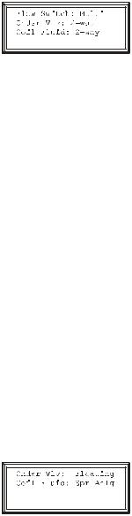
Path: Main > Setup > System # > System Config > Valve Types
Set the type of valves installed in your piping system. Each valve can be either two-way or three-way. Economizer-equipped Systems use three-way valves.
Flow Switch. Set the location of the optional flow switch in this System. The flow switch detects whether there is adequate liquid coolant (water) flow to maintain coil operation.
The Flow Switch setting indicates where the flow switch is installed:
•DX, for the liquid line entering the heat exchanger (to maintain head pressure in DX Systems)
•Multi, for the chilled water input to the MultiCool coil or chilled water coil (Systems using chilled water only)
•None, for air-cooled Modules with no MultiCool coil
Cndsr Vlv. The condenser fluid valve controls the flow of coolant into the heat exchanger or to the Economizer coil in direct expansion. Set the condenser fluid valve as either a twoor three-way valve.
Coil Fluid. The coil fluid valve controls the flow of coolant to the MultiCool, Chilled Water, or Economizer coil. Set the coil fluid valve as either a twoor three-way valve, depending on the configuration.
Actuator Types
Path: Main > Setup > System # > System Config > Actuator Types
Cndsr Vlv. Set the type of condenser valve actuator as Floating or None. The condenser valve is not present in In-row Modules.
•Floating Control maintains the position of the valve when the power is off.
•None indicates that no condenser valve is installed. Air-cooled Systems with no external water piping do not require a condenser valve actuator.
Coil Fluid. Set the Coil Fluid valve actuator to Floating, Spr Anlg, or None.
•Floating Control maintains the position of the valve when the power is off.
•Spring (Return) Analog closes the valve when the power is off.
•None indicates that the Module does not have a MultiCool, Chilled Water, or Economizer coil.
NetworkAIR IR Operation, Maintenance, and Troubleshooting |
11 |
Operation: Options for Fluid-Cooled Modules
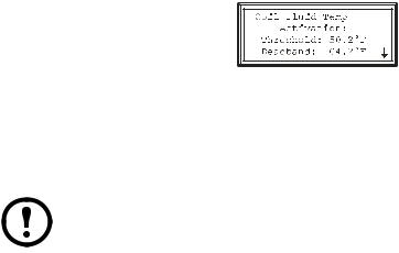
Coil Fluid Temp Activation Threshold and Deadband
Path: Main > Setup > System # > System Config > Coil Fluid Options
The selections for Coil Fluid Options help control the optional MultiCool coil or Economizer coil in equipped Systems. Set the temperature threshold and deadband for using the MultiCool coil or the Economizer coil. The System will compare the actual coolant temperature with the setpoint and deadband to determine if the coolant is at a temperature low enough to operate the coils.
The Coil Fluid Temp Activation threshold and deadband do not apply to Modules that use only a chilled water coil for cooling.
Note
Coil Fluid Temp Activation: Threshold. Set the coil fluid temperature activation threshold. The coolant temperature must be below the threshold to use the optional MultiCool coil or Economizer coil.
Coil Fluid Temp Activation: Deadband. Set the MultiCool or Economizer activation deadband. The deadband is the sensitivity range above the coil fluid temperature activation: threshold that determines when the controller will stop using the MultiCool coil or Economizer coil and when it will reengage the coil. For example, if the threshold is 50° F (10° C) and the deadband is
4° F (2.2° C), the controller will disengage the MultiCool coil or Economizer coil when the coolant temperature exceeds 54° F (12.2° C),and will not reengage the coil until the coolant temperature reaches 50° F (10° C).
12 |
NetworkAIR IR Operation, Maintenance, and Troubleshooting |
Set Up Contacts and Relays
The System can monitor external contact closure events. Possible applications include:
•Magnetic contact switches
•Window foil
•Tamper switches
•Heat detectors
•Water sensors
•Pressure sensors
•Building smoke and fire detection systems
You can set input contacts to cause alarm conditions based on their current state and a user-defined normal state. Output contacts can map internal alarms and events to outside devices.
See the Installation Manual to connect contacts and relays to your Programmable Customer Input/Output Module (PCIOM).
Input contacts
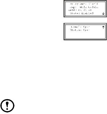
Path: Main > Setup > System # > Input/Output > Input Contacts
Each Main Module supports up to 16 user-defined input contacts. Each contact monitors a sensor and responds to changes in the state of the sensor (open or closed).
Name. Provide a unique name for each input contact.
Normal. Choose the normal state of the sensor. If the state changes, the controller takes the action defined by the Alarm Map setting.
Delay. Set how long the contact should be out of its normal state before the controller takes action (controlled by the Alarm Map setting).
NetworkAIR IR Operation, Maintenance, and Troubleshooting |
13 |
Operation: Set Up Contacts and Relays
Action. Set the System controller to respond to the change of status for an input in one of the following ways:
Map |
Description/Function |
|
|
Status Only |
Displays the event on the Active Alarms |
|
screen. Status-only events are not logged. |
|
|
Minor Alarm |
Activates the Warning LED and the alarm |
|
beeper. It also creates an entry in the event log. |
|
|
Major Alarm |
Activates the Alarm LED and the alarm |
|
beeper. It also creates an entry in the event log. |
|
|
Remote Run/Stop |
Shuts down the Modules normally, waiting for |
|
delay timers. |
|
|
Nonessential Lockout |
Deactivates modes set as nonessential and |
|
continues operation. |
|
|
Immediate Shutdown |
Shuts down the Modules immediately. It does |
|
not wait for the blower delay or compressor |
|
timers. |
|
|
Output relays
Path: Main > Setup > System # > Input/Output > Output Relays
The Main Module supports up to 16 user-defined output relays. Output relays respond to internal alarms and events by changing state to notify outside devices.
Relay Out. Choose the relay number to view or modify.
Map. Choose alarms or events to map to this relay:
•The first line of the map field displays the location of the event that is mapped to this relay. It can be a System, Main Module, Expansion Module 1, or Expansion Module 2 event.
•The second line displays the name of the event mapped to this relay.
Any input contact and output relay available in this System can be mapped to this relay.
Note
14 |
NetworkAIR IR Operation, Maintenance, and Troubleshooting |
Operation: Set Up Contacts and Relays
Action. The Action field changes as you scroll through the list of events that can be mapped to this relay. Remove indicates that the event is already associated with this relay. Add indicates that the event is not associated with this relay. Press the ENTER key and change the setting to map the displayed event to this relay or remove the displayed event from the list of events mapped to this relay.
Normal. Set the normal state for this relay. If the state of an alarm or event mapped to this relay changes from the normal state, the relay also changes state.
Reset Mappings. Set all of the output mappings back to their default settings.
NetworkAIR IR Operation, Maintenance, and Troubleshooting |
15 |
Set Up Module Configuration
The Module configuration settings help the controller determine which components are available and how the Module should operate.
The settings in the Module Configuration menu are defined at the factory. Changing the settings incorrectly can cause serious malfunctions and damage to your System. Only qualified service personnel should make changes to these settings.
Configure Module
Paths: Main > Setup > Module > Main Module > Module Config >Config Module
Main > Setup > Module > Expansion Module 1 > Module Config > Config Module
The Config Module menu contains settings that define the optional equipment available in the Module.
Output Cap. Indicate the output capacity of the Module, in kilowatts.
Heater. Indicate the type of heating equipment installed to run the reheat mode.
Humid. Indicate the type of humidifier equipment installed to run the humidification mode.
Conds Pump. Indicate the presence of a condensate pump. The pump feeds the condensate from the reservoir into the drain.
Blower. Indicate the type of blower controller for this Module.
ElecHeater Cap: indicate the capacity of the electric heater.
Alarm detectors
Paths: Main > Setup > Module > Main Module > Module Config > Set Alarm Detectors Main > Setup > Module > Expansion Module 1 > Module Config > Set Alarm Detectors
The Set Alarm Detectors settings indicate the presence of sensors in the Modules:
•Smoke — Indicate whether a smoke detector is installed in the Module.
•Fire — Indicate whether a fire detector (thermal sensor) is installed in the Module.
•Water — Indicate whether water leak detectors (loop detectors) are installed in the Module.
16 |
NetworkAIR IR Operation, Maintenance, and Troubleshooting |

Set Up Module Control
The Module Control options are configured and tuned during the commissioning of each Module.
The settings in the Module Control menu are defined at the factory. Changing the settings incorrectly can cause serious malfunctions and damage to your System. Only qualified service personnel should make changes to these settings.
Calibrate airflow manually
The System must be on and the blowers operating to calibrate the airflow manually. If either condition does not exist, the display will prompt you to turn on the System and
Note blowers.
Nom Coil DP: Set the nominal coil differential pressure.
Blower Spd. Adjust the frequency of the blower.
Coil DP: Displays the coil differential pressure at the bottom of the screen. As the blower frequency is adjusted, the coil differential pressure will change. The Std Dry column in the table below gives the recommended coil differential pressure for each Precision Air Conditioner model.
|
|
Coil Differential Pressure Values |
|
|
|
Model |
Std Dry |
Min |
Max |
Alarm Clear |
Airflow Alarm |
|
|
|
|
|
|
IR 40 CA |
0.44 |
0.34 |
0.54 |
0.24 |
0.20 |
All values are displayed in inches water column ("WC)
Calibrate airflow automatically
Nom Coil DP: Set the nominal coil differential pressure.
Start/Abort. Start the automatic calibration. If calibration is in progress, this line displays Abort.
Coil DP: Displays the coil differential pressure at the bottom of the screen. As the blower frequency is adjusted, the coil differential pressure will change. When the Coil DP value matches the Nom Coil DP value, the System will display Calibration Complete. If the System cannot align the two values, the System will display Calibration Failed after two minutes. You must manually calibrate the airflow if automatic calibration fails.
NetworkAIR IR Operation, Maintenance, and Troubleshooting |
17 |

Operation: Set Up Module Control
Reset variable frequency drive
Paths: Main > Setup > Module > Main Module > Module Control > Reset VFD # Main > Setup > Module > Expansion Module > Module Control > Reset VFD #
The Reset VFD option resets the variable frequency drive (VFD). The drive shuts down during a VFD # Fault Tolerance Exceeded alarm. The alarm occurs when the VFD detects three faults within thirty minutes. Use this function to restart the drive manually when the alarm condition is resolved.
VFD Fault Tolerance Exceeded alarms indicate a problem with the VFD. Check the event log for other VFD alarms before resetting the VFD.
Reset humidifier
Paths: Main > Setup > Module > Main Module > Module Control > Reset Humidifier Main > Setup > Module > Expansion Module > Module Control > Reset Humidifier
The Reset Humidifier option resets the humidifier. The humidifier shuts down during a Humidifier Fault Tolerance Exceeded alarm. The alarm occurs when the humidifier detects three faults within thirty minutes. Use this function to restart the humidifier manually when the alarm condition is resolved.
Humidifier Fault Tolerance Exceeded alarms indicate a problem with the humidifier. Check the event log for other humidifier alarms before resetting the humidifier.
The steam-electrode humidifier must be in Auto mode to operate.
Note
Set up Humidifier
Paths: Main > Setup > Module > Main Module > Module Control > Set up Humidifier Main > Setup > Module > Expansion Module > Module Control > Set up Humidifier
The Set up Humidifier option controls the steam-electrode humidifier mode.
Humidifier Mode. The steam-electrode humidifier can be set to one of three modes:
•Off — Removes power from the electrodes in the humidifier, while the cylinder remains filled.
•Drain — Removes power from the electrodes and drains the cylinder.
•Auto — Applies power to the humidifier and sets the humidifier to operate according to the Module controller.
18 |
NetworkAIR IR Operation, Maintenance, and Troubleshooting |

Operation: Set Up Module Control
Reset compressors
Paths: Main > Setup > Module > Main Module > Module Control > Reset Compressors Main > Setup > Module > Expansion Module > Module Control > Reset Compressors
The Reset Compressors option resets the compressors after an alarm. The compressors shut down during a Suction Pressure Low alarm. Use this function to restart the compressors manually when the alarm condition is resolved.
Low Suction Pressure alarms indicate a problem with the refrigeration system. Check the event log for other alarms before resetting the compressors.
NetworkAIR IR Operation, Maintenance, and Troubleshooting |
19 |
Control the Environment
The System controls the room environment by engaging one of four modes: Cool, Dehumidify, Reheat, or Humidify. These modes may work differently depending on the options and equipment installed in your Modules.
The environmental controls are set when your System is installed. Changing settings described in this section after the system has been commissioned may result in improper operation.
How the modes work
Cool. When the cool mode uses a Chilled Water coil, the output is determined by the difference between the setpoint and the measured air temperature (control temperature) of each of the Modules in the System (if more than one Module is present). The control temperature can be the average return sensor value, the average remote sensor value, or the maximum remote sensor value, depending on the System settings (Path: Main > Setup > System > System Setup > System Config > Sensor Setup)
See “Sensor setup” on page 9 to choose the source of the temperature value which the Module uses to calculate demand.
The Proportional plus Integral plus Derivative (PID) control loop calculates the output as demand increases and opens the valve controlling the flow of coolant into the coil. The PID adjusts the output as required to maintain the temperature at the setpoint.
See “PID controls” on page 23 for a description of the PID controls and instructions on tuning the fluid coil PID loop.
Reheat (Electric SCR and Modulating Hot Water). The SCR (silicon-controlled rectifier) electric reheat function is controlled by the reheat PID controller. The PID controller adjusts the output as required to maintain the temperature at the setpoint.
See “PID controls” on page 23 for a description of the PID controls and instructions on tuning the reheat PID loop.
Reheat (Hot Gas, Steam, Hot Water On/Off). The output of the hot gas, steam, and hot water on/off reheat options is determined by the difference between the setpoint and control temperature of the Module. When the control temperature at the Module reaches the setpoint minus the deadband, the reheat mode activates until the control temperature rises to the setpoint.
See “Deadbands” on page 22 for acceptable reheat deadband values.
20 |
NetworkAIR IR Operation, Maintenance, and Troubleshooting |
Loading...