


Analog Microelectronics AME8530AEEVLFX46, AME8530AEEVLFX44, AME8530AEEVLFX31, AME8530AEEVLFX29, AME8530AEEVLFX26 Datasheet
...
AME, Inc.
AME8510 / 8520 / 8530 |
Micropower μP Watch Dog Timer |
n General Description
The AME8510/8520/8530 family allows the user to customize the CPU monitoring function without any external components. The user has a large choice of reset voltage thresholds and output driver configurations, all of which are preset at the factory. Each wafer is trimmed to the customer's specifications.
These circuits will ignore fast negative going transients on VDD. The state of the reset output is guaranteed to be correct down to 1V.
After VDD crosses above a factory preset threshold, the AME8510/8520/8530 assert a reset signal. After a predetermined time (the “reset” interval) the reset is deasserted. If VDD ever drops below the threshold voltage a reset is asserted immediately. In addition to a supply monitoring function the AME8510/8520 also monitor transitions at the watch dog (WDI) input. If a logic transition does not occur at the WDI pin within a certain time interval (the “watchdog” interval) then a reset is asserted. The reset deasserts after the reset interval, as explained earlier.
n Features
lSmall packages: SOT-23-5
l7 voltage threshold options
lTight voltage threshold tolerance --- ±1.50%
l 12 output driver configuration options
lWide temperature range -------- -45oC to 85oC
lLow temperature coefficient --- 100ppm/oC (max)
lLow quiescent current < 3.0μA
l3 bonding options
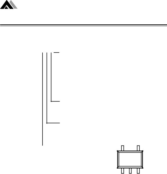
n Pin Configuration
The AME8510/8530 can both assert a reset manually |
SOT-25 Top View |
|
|
|
|
by pulling the MRB input to ground. |
|
|
|
VD D |
W D I |
Space saving SOT25 packages and micropower quiescent current make this family a natural for portable battery powered equipment.
AME8511 |
AME8510 |
RESET/
RESETB G N D M R B
n Applications |
V D D |
W D I |
|
lMotherboards
lComputer peripherals
lPortable electronics
lApplications using CPUs
lConsumer electronics
AME8511 |
AME8520 |
AME8510 |
RESET/ |
G N D |
RESETB/ |
|
R E S E T B |
R E S E T |
||
|
V D D M R B
AME851 |
AME8530 |
AME8530 |
RESET/ |
G N D |
RESETB/ |
R E S E T B |
R E S E T |
1
AME, Inc.
AME8510 / 8520 / 8530 |
Micropower μP Watch Dog Timer |
n Ordering Information
AME8510AEEV X X X XX
AME8520AEEV X X X XX
AME8530AEEV X X X XX
 VDD Threshold Voltage
22:VTH=2.19V
23:VTH=2.32V
26: VTH=2.63V
29: VTH=2.93V
31: VTH=3.08V
44: VTH=4.38V
46: VTH=4.63V
Watch Dog Interval (TWDNOM)
E: TD=1760mS
X: Without WDI option
Reset Time (TD2NOM)
F: TD=210mS
|
|
Output Driver Option |
|
|||
|
|
|
||||
|
|
|
|
|
|
|
|
|
|
Pin 1 |
|
Pin 3 |
|
|
|
|
Polarity |
* |
Polarity |
* |
|
|
|
|
|
|
|
|
|
A: |
RESETB |
PP |
N/A |
N/A |
|
|
B: |
RESETB |
OD |
N/A |
N/A |
|
|
|
|
|
|
|
|
|
C: |
RESET |
PP |
N/A |
N/A |
--For example-- |
|
D: |
RESET |
OD |
N/A |
N/A |
AME8520AEEVEFE29 means: |
|
E: |
RESETB |
PP |
RESET |
PP |
|
|
|
|
|
|
|
Output at pin 1 is RESETB, push pull |
|
F: |
RESETB |
PP |
RESET |
OD |
Output at pin 3 is RESET, push pull |
|
G: |
RESETB |
OD |
RESET |
PP |
|
|
|
|
|
|
|
Reset time is 210mS |
|
H: |
RESETB |
OD |
RESET |
OD |
Watch dog interval is 1760mS |
|
I: |
RESET |
PP |
RESETB |
PP |
VDD threshold voltage is 2.93V |
|
|
|
|
|
|
|
J: |
RESET |
PP |
RESETB |
OD |
|
No temperature shutdown |
|
K: |
RESET |
OD |
RESETB |
PP |
|
|
L: |
RESET |
OD |
RESETB |
OD |
|
|
|
|
|
|
|
VDD |
WDI/MRB |
AME851 |
8510/20/30 |
AME8530 |
PIN 1 GND PIN 3
*Output Driver Chart Explanation: PP = Push pull output
OD = Open drain output N/A = Not available (8510) RESET = Active high RESETB = Active low
Please consult AME sales office or authorized Rep. for other RESET TIME interval and Watch Dog time interval.
2

AME, Inc.
AME8510 / 8520 / 8530 |
Micropower μP Watch Dog Timer |
|||
|
|
|
|
|
|
|
|
|
|
n Absolute Maximum Ratings |
|
|
|
|
|
|
|
|
|
|
Parameter |
Maximum |
Unit |
|
|
|
|
|
|
|
Supply Voltage |
6 |
V |
|
|
|
|
|
|
|
ESD Classification |
B |
|
|
|
|
|
|
|
Caution: Stress above the listed absolute rating may cause permanent damage to the device |
||||
n Recommended Operating Conditions |
|
|
|
|
|
|
|
|
|
|
Parameter |
Rating |
|
|
|
|
|
|
|
|
Supply Voltage |
0.9 - 5 V |
|
|
|
|
|
|
|
|
Ambient Temperature Range |
- 40 to +85 oC |
|
|
|
|
|
|
|
|
Junction Temperature |
- 40 to +125 oC |
|
|
|
|
|
|
|
n Thermal Information |
|
|
|
|
|
|
|
|
|
|
Parameter |
Maximum |
Unit |
|
|
|
|
|
|
|
Thermal Resistance (SOT-25) |
256 |
oC /W |
|
|
|
|
|
|
|
Maximum Junction Temperature |
150 |
oC |
|
|
Maximum Lead Temperature ( 10 Sec) |
300 |
oC |
|
|
|
|
|
|
3
 Loading...