


 Loading...
R-410A REMOTE OUTDOOR UNIT
USER’S INFORMATION MANUAL
R
C R
Thank you for investing in our quality Comfort System. The air conditioner you have purchased is part of a Split System and has both indoor and outdoor components. With proper installation and maintenance, it should provide you with years of dependable service.
Take time to familiarize yourself with the information concerning unit features, operation, and maintenance contained within this manual.
Check the serial plate for model identification. Record this information on the last page of this booklet.
Please read this User’s Manual carefully, and follow the instructions given. Keep it in a safe place for future reference.
Your warranty certificate is supplied with this unit. Read it carefully and note what is covered. Keep it and a copy of the bill received from your dealer in a safe place for future reference. This can serve as proof of the date of installation.


 ®is a trademark of Maytag Corporation and is used under license to Goodman Company, L.P. All rights reserved.
Part No. 10659207 |
Goodman Company, L.P. |
|
1810 Wilson Parkway • Fayetteville, Tennessee 37334 |
||
Printed in USA |
||
www.amana-hac.com |
||
|
2003-2004 Goodman Company, L.P.
Effective: June 2004

ATTENTION INSTALLING PERSONNEL
As a professional installer you have an obligation to know the product better than the customer. This includes all safety precautions and related items.
Prior to actual installation, thoroughly familiarize yourself with this Manual. Pay special attention to all safety warnings. Often during installation or repair it is possible to place yourself in a position which is more hazardous than when the unit is in operation.
Remember, it is your responsibility to install the product safely and to know it well enough to be able to instruct a customer in its safe use.
Safety is a matter of common sense...a matter of thinking before acting. Most dealers have a list of specific good safety practices...follow them.
The precautions listed in this Installation Manual are intended as supplemental to existing practices. However, if there is a direct conflict between existing practices and the content of this manual, the precautions listed here take precedence.
Remember to leave this manual with the homeowner.
Table of Contents |
|
Typical Thermostat Operation ................................................................ |
3 |
General Information ................................................................................ |
5 |
Electrical Power Supply.................................................................................... |
5 |
Refrigerant ....................................................................................................... |
5 |
Annual Maintenance ........................................................................................ |
6 |
Routine Maintenance ....................................................................................... |
6 |
Replace or Clean Indoor Filter ............................................................................ |
6 |
Clean Outside Coil (Qualified Servicer only) ....................................................... |
6 |
Compressor ........................................................................................................... |
6 |
Motors ................................................................................................................... |
6 |
IMPORTANT SYSTEM INFORMATION ......................................................... |
10 |
2
Typical Thermostat Operation
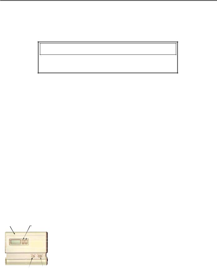
Your thermostat is the control center for your Split System. It is very important that the thermostat be located where it can best “sense” the average room temperature. It must not be located where it is exposed to hot or cold drafts or to hot or cold spots on the wall, such as those received from outside walls, walls with pipes inside, or from openings into the attic. Because of the wide variety of programmable thermostats available, we cannot describe how all of them work. However, a typical thermostat has two switches: a SYSTEM switch and a FAN switch.
 WARNING
To avoid possible equipment damage, personal injury, fire or death, the following instructions must be observed regarding unit location, air requirements and operating procedures.
The SYSTEM switch can include settings of HEAT, OFF, COOL, AUTO:
HEAT – Your comfort system provides heat when the temperature in the room falls below the temperature selected. No matter how warm the room becomes, cooling will not be provided.
OFF – Your comfort system will not provide heating or cooling, no matter how cold or hot the room becomes.
COOL– Your comfort system provides cooling when the temperature in the room rises above the temperature selected. No matter how cold the room becomes, heat will not be provided.
AUTO– Your comfort system will provide heat when the temperature in the room falls below the temperature selected, and will provide cooling when the temperature in the room rises above the temperature selected. With most of these thermostats, you will have a temperature range in which neither heating or cooling is being provided. The AUTO setting will help your building avoid temperature extremes, but it may increase your operating costs.
Room Temperature |
|
Cool/Heat |
|
|
|
Thermostat |
|
|
|
||
Temperature |
|
|
|||
|
Control Dials |
|
|
||
|
|
|
|
|
|
|
|
|
System |
Fan |
Action |
|
|
|
Switch |
Switch |
|
|
|
|
OFF |
AUTO |
None |
|
|
|
COOL |
AUTO |
System only cools, fan |
|
|
|
cycles off and on. |
||
|
|
|
COOL |
ON |
System only cools, fan |
|
|
|
runs all the time. |
||
|
|
|
HEAT |
AUTO |
System only heats, fan |
|
|
|
cycles off and on. |
||
|
|
|
HEAT |
ON |
System only heats, fan |
|
|
|
runs all the time. |
||
|
|
|
OFF |
ON |
No heating or cooling, |
|
|
|
fan runs all the time. |
||
|
Fan Switch |
Cool/Heat |
|
|
|
|
Switch |
|
|
||
Typical Thermostat
EMERGENCY
HEAT – EMERGENCY HEAT is only used with heat pumps. Emergency heat means the compressor (i.e., the outdoor unit) is turned off, and your backup source (if present) will provide heat when the temperatures in the room falls below the temperature selected. (No matter how warm the room becomes, cooling will not be provided.) The backup source is usually electricity, but it may be a gas or oil furnace. The EMERGENCY HEAT setting may be used if you suspect a problem exists with the heat provided by the compressor, but your dealer is not able to service it immediately. With some comfort systems, the EMERGENCY HEAT setting may also be used to provide a quicker warm-up of the room. Once the warm-up is completed, you should usually return the system switch to the HEAT or AUTO setting. If you leave the system switch in the EMERGENCY HEAT setting, it may increase your operating costs.
NOTE: Keeping your windows closed whenever the thermostat SYSTEM switch is in the HEAT, COOL or AUTO setting will keep operating costs down.
The Fan switch may include settings of AUTO and ON:
AUTO– The indoor fan is operating when heating or cooling is being provided. NOTE: With some comfort systems, the indoor fan may continue to run for a short time after the compressor shuts off. With most gas furnaces, the indoor fan will start a short time after the burners are lit, and will keep running for a short time after the burners shut off. When your comfort system is not heating or cooling, the fan will not run.
ON – The indoor fan runs continuously.
3
Loading...