


PTAC HYDRONIC HEAT KIT HVK03E AND HWK03E
INSTALLATION INSTRUCTIONS
DESCRIPTION
The PTAC Hydronic Kit is an enclosure kit that provides complete coverage of all PTAC plumbing and coils while still allowing access to controls. The kit can only be installed where there is a central boiler for heating the water. It does not affect unit heating and cooling operations. The hydronic kit chassis slides out for service without removing any hydronic plumbing. The electrical connections are plug-in type to assist in kit installation.
NOTE: Heat pump models will operate on heat pump function down to the switchover temperature before operating on hydronic heat.
Freeze Protection
For PTAC Hydronic Coil freeze protection on hot water systems, the hydronic system should use an antifreeze
solution. However, the addition of antifreeze will reduce the capacity of the hydronic coil and affect system sizing. The higher the antifreeze concentration, the greater the capacity reduction. Therefore, for optimum unit performance, only use an antifreeze concentration that will protect to the lowest ambient temperature expected. A 20% solution will protect to approximately 15°F. A 50% solution protect to -35°F.
Use an antifreeze that is formulated for hydronic use. DO
NOT USE AUTOMOTIVE OR PETROLEUM BASED PRODUCTS.
Tools Required
1/4 Inch Electric Drill
1/8 Inch Diameter Drill Bit Center Punch and Hammer 6 Foot Rule
Combination Square
1/4 Inch Nut Driver or Socket 5/16 Inch Nut Driver or Socket Torch, Solder, Flux, etc.
 RECOGNIZE THIS SYMBOL AS A SAFETY PRECAUTION.
ATTENTION INSTALLING PERSONNEL
As a professional installer you have an obligation to know the product better than the customer. This includes all safety precautions and related items.
Prior to actual installation, thoroughly familiarize yourself with this Instruction Manual. Pay special attention to all safety warnings. Often during installation or repair it is possible to place yourself in a position which is more hazardous than when the unit is in operation.
Remember, it is your responsibility to install the product safely and to know it well enough to be able to instruct a customer in its safe use.
Safety is a matter of common sense...a matter of thinking before acting. Most dealers have a list of specific good safety practices...follow them.
The precautions listed in this Installation Manual are intended as supplemental to existing practices. However, if there is a direct conflict between existing practices and the content of this manual, the precautions listed here take precedence.
|
Goodman Company, L.P. |
|
|
|
|
|
|
|
|
|
|
|
|
IO-386B |
5151 San Felipe, Suite 500 • Houston, TX 77056 |
|
|
|
|
|
|
|
|
|
|
|
|
|
|
|
|
|
|
|
|
|
|
|
|
||
February 2011 |
www.amana-ptac.com |
|
|
|
|
|
|
|
|
|
|
|
|
|
© 2010 - 2011 Goodman Company, L.P. |
|
|
|
|
|
|
|
|
|
|
|
|
JOB PREPARATION
Before installing the hydronic kit, determine the following:
•Whether a 2-way or 3-way normally open or normally closed valve is required.
•If an end switch is required to control the circulating pump. (Information relating to U.L. approved valves and current loads is shown on the kit label and is repeated in the following figure).
NOTE: WHEN HYDRONIC HEAT IS USED, DISREGARD THE MINIMUM CIRCUIT AMPACITY AND MAXIMUM FUSE SIZE SHOWN ON THE AUXILIARY NAMEPLATE FOR FIELD INSTALLED HEATERS. USE VALVES SHOWN ON THE MASTER UNIT NAMEPLATE.
CAUTION: VOLTAGE RATING OF VALVE IS 24VAC AND DOES NOT CORRESPOND TO
VOLTAGE RATING ON THE UNIT NAMEPLATE.
NOTE: WHEN HYDRONIC HEAT KIT IS
EMPLOYED, THE FOLLOWING LOADS
OPERATE CONCURRENTLY:
|
HOT WATER |
STEAM |
|
|
|
ERIE MANUFACTURING CO. |
654C0507EA01 |
654C0407EA01 |
UNIT VOLTAGE RATING |
230/208 |
265 |
|
654C0527EA01 |
654C0427EA01 |
FAN MOTOR AMPS |
.6 |
.6 |
|
654C0509EA01 |
VS2212G14A02A |
MOTORIZED VALVE, WATTS |
6.5 |
6.5 |
|
654C0529EA01 |
VS2212G24A02A |
|
|
|
|
VT2212G14A02A |
|
|
|
|
|
VT2212G24A02A |
|
|
|
|
|
VT3213G14A02A |
|
|
|
|
BARBER-COLMAN |
VA-1403-201 |
VA-9224-201 |
MAX. WATER TEMPERATURE |
200° F |
|
|
VA-1403-301 |
VA-9214-201 |
MAX. WATER PRESSURE |
200 PSIG |
|
|
VA-3403-201 |
|
MAX. STEAM PRESSURE |
5.0 PSIG |
|
HONEYWELL |
V8043A |
|
|
|
|
|
V8043B |
V8043J |
|
|
|
|
V8044A |
|
|
|
|
Also, ensure that the following steps are completed and a hydronic model chassis is installed before installation.
NOTE: The hydronic chassis MUST have a model number in which the 10th, 11th, 12th or 13th digit is H.
1.Wall sleeve is installed and completely sealed.
It must extend at least 3” and no more than 3-1/8” past the finished interior wall in order to properly install the hydronic kit.
2.All plumbing stub-outs are completed.
3.Unit chassis is uncrated, uninstalled, and not yet connected to an electrical source.
INSTALLATION
The installation and servicing of the equipment referred to in this booklet should be performed by qualified, experienced technicians.
Be sure to engage the services of a qualified water treatment specialist to determine what water treatment, if any, is needed. The manufacturer will not assume responsibility for equipment failures resulting from untreated or improperly treated water.


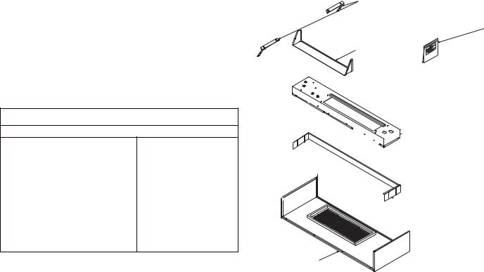
This Installation kit includes:
Item |
Qty |
Description |
A |
1 |
Transition |
B1 Hydronic Skirt
C1 Hydronic Top Assy
D1 Hydronic Front Assy
E2 Support Brackets
F1 Bag Assembly containing:
Installation Instructions, Gasket foam,
8 - 3/8” #8 screws
2 - 1/2” #8 screws
4 - 1/2” #10 screws
1 #10 machine screw
1 snap bushing
1 valve harness
4 wire nuts
2
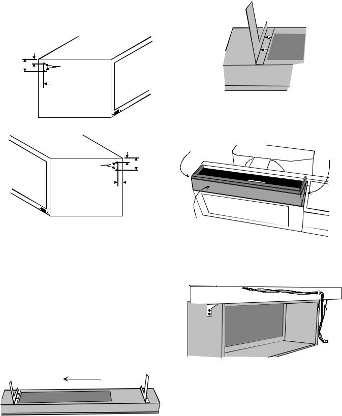
1.Drill two 1/8” diameter holes on both sides of wall sleeve as shown (Figure 1).
NOTE: If there is not enough room to drill holes from the side then drill holes from inside the wall sleeve.
Wall
3-1/4" Sleeve
5" |
|
1/8" Holes |
|
||
|
|
|
2-1/4" 
Indoor
Right
Side
Wall
Sleeve 3-1/4"
1/8" Holes |
|
|
|
5" |
||
|
|
|
||||
|
|
|
|
|
2-1/4" |
|
|
|
|
|
|
||
Indoor
Left
Side
Figure 1
2.Remove the hydronic kit from its packaging. Recycle the cardboard packaging material.
3.Mount the two support brackets to the bottom of the hydronic top (Figure 2) with four (4) 3/8-inch #8 supplied screws.
On HVK03E Hydronic Steam Kits, do not use 1/4 inch head, 3/8 inch long, #8 screws to attach the left support bracket to the hydronic top. Use the provided two 5/16 inch painted head, 1/4 inch long, #8 screws in place of these longer screws. (Figure 3)
NOTE: Failure to use the 1/4 inch long screws instead of the 3/8 inch long screws may result in leaks of the hydronic steam coil.
Slide Brackets Before Tightening Screws
Figure 2
Move the brackets to the left so that screws are located in right side of slot and tighten screws (Figure 3).
Figure 3
4.Mount the transition to the chassis with two 1/2-inch #8 supplied screws (Figure 4).
1/2" #8 Screw |
|
|
|
|
|
||
|
|
1/2" #8 Screw |
|||||
(May be covered |
|||||||
|
(May be covered |
||||||
by gasket) |
|
|
|
||||
|
|
|
|
by gasket) |
|
||
|
|
|
|
|
|
||
|
|
|
|
|
|
|
|
Transition
Figure 4
5.Position the hydronic top with support brackets to the wall sleeve and fasten the support brackets to the drilled holes in the wall sleeve with four 1/2-inch #10 supplied screws. (Figure 5)
Figure 5
6.Place the chassis back into the wall sleeve and secure chassis to wall sleeve.
7.Measure the actual distance “D” (Figure 6) from the bottom of the chassis basepan to the finished floor to determine how far to extend the skirt below the metal front. If the distance is less than two inches, trim the skirt per Figure 7 so that it will not interfere with the gasket or block the inlet air on the front. In Figure 7, “Y” dimension equals 2” minus actual “D” dimension.
3

Basepan
D = 1/2" to 3-3/4"
Floor 
W A L L
Hydronic Front
(Inside Surface)
Skirt
3/8" #8 Screws
(Two On Each Side)
Figure 9
9. Remove the six screws from the top of the hydronic top. Lift the hydronic top straight up and set aside along with the six screws (Figure 10).
Figure 6
Y = 2" - D
|
|
2 |
|
|
|
|
|
|
|
|
|
|
|
|
|
|
|
|
|
|
|
8 |
|
6- |
|
" |
|
|
|
||
3/ |
|
|
|
4" |
|
|
|
Figure 7
Exterior
Wall
Hydronic
Front Wall
Sleeve
Skirt
Between 0" to 3" Finished
Floor Figure 8
8.Mount the skirt to the metal front with the four remaining 3/8” #8 supplied screws (Figure 9).
NOTE: Skirt is attached to front of top piece during shipping.
Figure 10
10.Position the wires from the freeze thermostat found on the left side of the hydronic top so the wires slide through the slot opening in the hydronic top.
Place all wires into the supplied snap bushing (Figure 11.
SNAP BUSHING
Figure 11
11.Snap the grommet into the hydronic top and pull the wires forward to take out the slack in the wires (Figure 12).
4
 Loading...