


HDC12
Amana HDC12, HDC21, HDC10, HDC18, CRC21T2RL User Manual
...
Service
Commercial
Microwave Oven
This Base Manual covers Commercial
Microwave Ovens with 120/230 V, 60 Hz.
Refer to individual Technical Sheet for
information on specific models.
This manual includes, but is not limited to
the following:
CRC18T2OG P1323006M, P1323015M
CRC21T2RL P1323007M, P1323017M
HDC10 P1323008M
HDC12 P1323009M
HDC18 P1323003M, P1323013M
HDC18SD P1323004M, P1323014M
HDC21 P1323005M, P1323016M
Service Manual for
Amana
®
This manual is to be used by qualified appliance
technicians only. Amana does not assume any
responsibility for property damage or personal
injury for improper service procedures done by an
unqualified person.
RS2240002
Revision 1
October 2000

!
!
Important Product Information
!
WARNING
Precautions to be observed before and during servicing
to avoid possible exposure to excessive microwave
energy .
(A) Do not operate or allow oven to be operated with the
door open.
(B ) Make the following safety checks on all ovens to be
serviced before activating the magnetron or other
microwave source, and make repairs as necessary:
• Interlock operation
• Proper door closing
• Seal and sealing surfaces (arcing, wear, and other
damage)
• Damage to or loosening of hinges and latches
• Evidence of dropping or abuse
(C ) Before turning on microwave power for any service
test or inspection within the microwave generating
compartments, check the magnetron, wave guide or
transmission line, and cavity for proper alignment,
integrity , and connections.
(D ) Any defective or misadjusted components in the
interlock, monitor, door seal, and microwave
generation and transmission systems shall be
repaired, replaced, or adjusted by procedures
described in this manual before oven is released to
the consumer.
(E) Check microwave leakage to verify compliance with
the Federal Performance Standard should be
performed on each oven prior to release to the
consumer.
WIRING
Good service practice is to never route wiring over
terminals and/or sharp edges. This applies to any wiring
without regard to the circuit voltage. Wire insulation
material and thickness is designed and regulated for
electrical spacing purpose only , but cannot always be
relied upon because of possible cuts and/or abrasions,
which can occur during servicing.
WA RNING
To avoid risk of electrical shock, injury, or death, make
sure these grounding instructions are followed.
Grounding Instructions
WA RNIN G
Do not remove grounding prong when installing
grounded appliance in a home or business that does
not have three wire grounding receptacle, under no
condition is grounding prong to be cut off or removed. It
is the personal responsibility of the consumer to
contact a qualified electrician and have properly
grounded three prong wall receptacle installed in
accordance with appropriate electrical codes.
Should a two prong adapter plug be required temporarily
it is the personal responsibility of the consumer to have it
replaced with properly grounded three prong receptacle or
the two prong adapter properly grounded by a qualified
electrician in accordance with appropriate electrical
codes.
Servicing of Grounded Products
The standard accepted color coding for grounding wires
is GREEN or GREEN WITH YELLOW STRIPE. These
ground leads are NOT to be used as current carrying
conductors. It is extremely important that the technician
replace any and all grounds prior to completion of the
service call. Under no condition should ground wire be left
off causing a potential hazard to technicians and
consumer.
RS2240002 Rev. 1 2

Table of Contents
Important Product Information ..................................... 2
Impo rtant I nform ation .................................................. 4
Important Safety Information ....................................... 5
Product Information
Antenna Blade ......................................................... 8
Blower/Fan Assembly.............................................. 8
Grease Shield.......................................................... 8
Door Interlock and Monitoring Switch....................... 8
Auto Transformer ..................................................... 8
Transformer High V oltage......................................... 8
High Voltage Capacitor ............................................ 8
High Voltage Diode (Rectifier) .................................. 8
Magnetron ............................................................... 8
Thermal Cutout Protectors....................................... 8
T ouch Panels........................................................... 8
Triac ........................................................................ 8
Antenna Motor(s) ..................................................... 8
Installation
Unpacking Oven ...................................................... 9
Oven Placement ...................................................... 9
Radio Interference ....................................................9
Grounding Instructions ............................................. 9
Care and Cleaning
Changing Oven Light Bulb...................................... 10
Cleaning Interior, Exterior , and Door....................... 10
Cleaning Splatter Shield ........................................ 10
Cleaning Air Intake Filter ....................................... 1 1
Cleaning Discharge Air Vents ................................ 1 1
Control Panel Features ............................................. 1 2
Displays
Cooking Methods................................................... 13
Cooking Displays................................................... 13
Programming Displays........................................... 13
Operation
Interrupting Operation ............................................ 1 4
Canceling Mistakes ............................................... 14
Operating Preprogrammed Pads............................ 14
Using X2 Pad......................................................... 1 4
Manual Time Entry ................................................ 14
Programming Instructions
Memory Pads ........................................................ 15
Multiple Cooking Stages ........................................ 1 5
X2 Quantity Feature ............................................... 15
User Options ......................................................... 16
Component T esting Procedures ................................ 17
T est Modes
Power T est............................................................. 21
Microwave Energy Leakage T esting
Equipmen t ............................................................. 2 2
Procedure for Measuring Radiation Leakage.......... 22
Measurement With the Outer Case Removed ........ 22
Measurement With a Fully Assembled Oven ......... 22
Record Keeping and Notification
After Measurement ................................................ 22
Troubleshooting
Initial Power Up .................................................. 23
Standby Condition .............................................. 24
Cook Condition................................................... 25
Disassembly
Door Removal ........................................................ 26
Inner Door/Window Removal .................................. 26
Door Disassembly ................................................. 2 6
Door Handle........................................................... 26
Hinge ..................................................................... 26
Interlock Switch Assembly .................................... 27
Switch Replacement / Door Adjustment ................ 28
Outer Case ............................................................ 29
Back Panel............................................................ 29
Grease Shield........................................................ 29
Antenna Assembly–T op......................................... 29
Antenna Motor–T op................................................ 29
Oven Tray Removal ................................................ 29
Antenna Assembly–Bottom ................................... 29
Antenna Motor–Bottom.......................................... 30
T ouch Panel Assembly.......................................... 3 0
Control Board ........................................................ 30
Interlock Switch Assembly .................................... 30
Magnetron Cutout (TCO) ........................................ 3 0
Triac ...................................................................... 30
Diodes ................................................................... 30
Magnetron ............................................................. 30
Cavity Thermal Cutout Replacement ...................... 3 1
Fuse ...................................................................... 31
Blower Wheel and Motor........................................ 31
Fan Blade .............................................................. 3 1
Auto Transformer ................................................... 31
High Voltage T ransformer ....................................... 3 2
Capacitor ............................................................... 3 2
Power Cord............................................................ 32
Lamp Receptacle................................................... 32
Replacing Oven Lamp ............................................ 3 2
Component Location
Figure 1 .............................................................. 33
Figure 2 .............................................................. 34
Figure 3 .............................................................. 35
Amana Appliances • 2800 220thTrail • Amana, Iowa • 52204-0001 • Printed in the U.S.A.
3 RS2240002 Rev. 1
!
!
!
!
!
Important Information
Pride and workmanship go into every product to provide our customers with quality products. It is possible, however,
that during its lifetime a product may require service. Products should be serviced only by a qualified service
technician who is familiar with the safety procedures required in the repair and who is equipped with the proper tools,
parts, testing instruments and the appropriate service manual. REVIEW ALL SERVICE INFORMATION IN THE
APPROPRIATE SERVICE MANUAL BEFORE BEGINNING REPAIRS.
Important Notices for Consumers and Servicers
WARNING
T o avoid risk of serious injury or death, repairs should not be attempted by an unauthorized personnel, dangerous
conditions (such as exposure to electrical shock) may result.
CAUTION
Amana will not be responsible for any injury or property damage from improper service procedures. If prefroming
service on your own product, assume responsibility for any personal injury or property damage which may result.
To locate an authorized servicer, please consult your telephone book or the dealer from whom you purchased this
product. For further assistance, please contact:
CONSUMER AFFAIRS DEPT. OR 1-319-622-5511
AMANA REFRIGERATION, INC. CALL and ask for
AMANA, IOWA 52204 Consumer Affairs
If outside the United States contact:
AMANA
ATTN: CONSUMER AFFAIRS DEPT
2800 220th Trail
AMANA, IOWA 52204, USA
Telephone: (319) 622-5511
Facsimile: (319) 622-2180
TELEX: 4330076 AMANA
CABLE: "AMANA", AMANA, IOWA, USA
Recognize Safety Symbols, Words, and Labels
DANGER
DANGER - Immediate hazards which WILL result in severe personal injury or death.
WA RNIN G
WARNING - Hazards or unsafe practices which COULD result in severe personal injury or death.
CAUTION
CAUTION - Hazards or unsafe practices which COULD result in minor personal injury or product or property
damage.
RS2240002 Rev. 1 4

!
Important Safety Information
CAUTION
Do not become exposed to radiation from the
microwave generator or other parts conducting
microwave energy .
Basic design of this microwave oven makes it an
inherently safe device to both use and service. However,
there are some precautions which should be followed
when servicing microwave oven to maintain this safety .
These are as follows:
1. Always operate unit from an adequately grounded
outlet. Do not operate on a two-wire extension cord.
2. Before servicing unit (if unit is operable) perform
microwave leakage test.
3. Oven should never be operated if door does not fit
properly against seal, hinge/hinge bearings are
damaged or broken; choke is damaged, (pieces
missing, etc.); or any other visible damage can be
noted. Check choke area to ensure that this area is
clean and free of all foreign matter. If any above
problems occur take the following steps:
• T ell the user not to operate the oven.
• Contact Amana immediately.
4. If oven operates with door open and produces
microwave energy , take the following steps:
• T ell the user not to operate the oven.
• Contact Amana immediately.
5. Always have oven disconnected when outer case is
removed except when making "live" tests called for in
the service manual. Do not reach into equipment
area while unit is energized. Make all connections
for the test and check them for tightness before
plugging cord into outlet.
6. Always ground capacitors on magnetron filter box and
H.V . capacitor with an insulated-handle screwdriver
before working in high voltage area of equipment
compartment. Some types of failures will leave a
charge in capacitors and the discharge could cause a
reflex action which could make you injure yourself.
7. In the area of the transformer, capacitor , diode, and
magnetron there is HIGH VOL T AGE. When unit is
operating, keep area clean and free of anything which
could possibly cause an arc or ground, etc.
8. DO NOT for any reason defeat interlock switches,
there is no valid reason for this action at any time;
nor will it be condoned by Amana.
9. Microwave oven should never be operated with:
• Any components removed and/or bypassed
• Any of the safety interlocks are found to be
defective
• Any of the seal surfaces are defective, missing, or
damaged
10.To ensure that unit does not emit excessive
microwave leakage and to meet Department of Health
and Human Services guidelines check oven for
microwave leakage using Narda Model 8100, 8200,
Holaday HI1500, HI1501, or Simpson 380M leakage
monitor as outlined in instructions. Maximum leakage
level allowed is 4mw/cm2 .
1 1.If servicer encounters an emission reading over 4mw/
cm2, servicer is to cease repair and contact Amana
Service Department immediately for further direction.
Amana will contact the proper government agency
upon verification of test results.
12.Install or locate this equipment ONLY in accordance
with the installation instructions in this manual.
13.Some products such as whole eggs and sealed
containers – for example, closed glass jars – may
explode and SHOULD NOT be HEA TED in this
equipment.
14.Use this equipment ONLY for its intended use as
described in this manual. Do not use corrosive
chemicals or vapors in this equipment. This type of
equipment is specifically designed to heat or cook. It
is not designed for industrial or laboratory use.
15.As with any equipment, CLOSE SUPERVISION is
necessary when used by CHILDREN.
16.DO NOT operate this equipment if it has a damaged
cord or plug, if it is not working properly , or if it has
been damaged or dropped.
17.This equipment, including power cord, must be
serviced ONL Y by qualified service personnel. Special
tools are required to service equipment. Contact
nearest authorized service facility for examination,
repair, or adjustment.
18.DO NOT cover or block any openings on the
equipment.
19.DO NOT store this equipment outdoors. DO NOT use
this product near water – for example, near a kitchen
sink, in a wet basement, or near a swimming pool,
and the like.
20.DO NOT immerse cord or plug in water.
21.Keep cord AWA Y from HEATED surfaces.
22.DO NOT let cord hang over edge of table or counter.
5 RS2240002 Rev. 1

Important Safety Information
!
CAUTION
To avoid personal injury or property damage, observe the following:
1. Briskly stir or pour liquids before heating with
microwave energy to prevent spontaneous boiling
or eruption. Do not overheat. If air is not mixed
into a liquid, liquid can erupt in oven or after
removal from oven.
2. Do not deep fat fry in oven. Fat could overheat and
be hazardous to handle.
3. Do not cook or reheat eggs in shell or with an
unbroken yolk using microwave energy . Pressure
may build up and erupt. Pierce yolk with fork or
knife before cooking.
4. Pierce skin of potatoes, tomatoes, and similar
foods before cooking with microwave energy . When
skin is pierced, steam escapes evenly .
5. Do not operate equipment without load or food in
oven cavity .
6. Use only popcorn in packages designed and
labeled for microwave use. Popping time varies
depending on oven wattage. Do not continue to
heat after popping has stopped. Popcorn will
scorch or burn. Do not leave oven unattended.
7. Do not use regular cooking thermometers in oven.
Most cooking thermometers contain mercury and
may cause an electrical arc, malfunction, or
damage to oven.
8. Do not heat baby bottles in oven.
9. Do not use metal utensils in oven.
10. Never use paper, plastic, or other combustible
materials that are not intended for cooking.
11. When cooking with paper , plastic, or other
combustible materials, follow manufacturer's
recommendations on product use.
12. Do not use paper towels which contain nylonor
other synthetic fibers. Heated synthetics could melt
and cause paper to ignite.
13. Do not heat sealed containers or plastic bags
in oven. Food or liquid could expand quickly and
cause container or bag to break. Pierce or open
container or bag before heating.
14. To avoid pacemaker malfunction, consult physician
or pacemaker manufacture about effects of
microwave energy on pacemaker .
PRECAUTIONS TO AVOID POSSIBLE EXPOSURE
TO EXCESSIVE MICROWA VE ENERGY
a. DO NOT attempt to operate this oven with the door
open since open-door operation can result in harmful
exposure to microwave energy . It is important not to
defeat or tamper with the safety interlocks.
b. DO NOT place any object between the oven front
face and the door or allow soil or cleaner residue to
accumulate on sealing surfaces.
RS2240002 Rev. 1 6
c. DO NOT operater the oven if it is damaged. It
particularly important that the oven door close
properly and that there is no damage to the:
(1) door (bent), (2) hinges and latches (broken or
loosened), (3) door seal and sealing surface.
d. The oven should NOT be adjusted or repaired by
anyone except properly qualified service personnel.
!
Important Safety Information
!
Recognize this symbol as a SAFETY message
WARNING
When using electrical equipment, basic safety precautions should be followed to reduce the risk of burns, electrical
shock, fire, or injury to persons.
1. READ all instructions before using equipment.
2. READ AND FOLLOW the specific “PRECAUTIONS
TO A VOID POSSIBLE EXPOSURE TO
EXCESSIVE MICROWA VE ENERGY”.
3. This equipment MUST BE GROUNDED. Connect
only to properly GROUNDED outlet. See
“GROUNDING INSTRUCTIONS”.
4. Install or locate this equipment ONL Y in accordance
with the installation instructions in this manual.
5. Some products such as whole eggs and sealed
containers – for example, closed glass jars – may
explode and SHOULD NOT be HEA TED in this
oven.
6. Use this equipment ONLY for its intended use as
described in this manual. Do not use corrosive
chemicals or vapors in this equipment. This type of
oven is specifically designed to heat or cook. It is
not designed for industrial or laboratory use.
7. As with any equipment, CLOSE SUPERVISION is
necessary when used by CHILDREN.
8. DO NOT operate this equipment if it has a damaged
cord or plug, if it is not working properly , or if it has
been damaged or dropped.
9. This equipment, including power cord, must be
serviced ONLY by qualified service personnel.
Special tools are required to service equipment.
Contact nearest authorized service facility for
examination, repair, or adjustment.
10. DO NOT cover or block filter or other openings
on equipment.
11. DO NOT store this equipment outdoors. DO NOT
use this product near water – for example, near a
kitchen sink, in a wet basement, or near a
swimming pool, and the like.
12. DO NOT immerse cord or plug in water.
13. Keep cord AWA Y from HEA TED surfaces.
14. DO NOT let cord hang over edge of table or counter.
15. See door cleaning instructions in “Care and
Cleaning” section.
16. For commercial use only.
CAUTION
To reduce the risk of fire in the oven cavity:
a. DO NOT overcook food. Carefully attend equipment
if paper , plastic, or other combustible materials are
placed inside the oven to facilitate cooking.
b. Remove wire twist-ties from paper or plastic bags
before placing bag in oven.
c. KEEP oven DOOR CLOSED, turn oven off, and
disconnect the power cord, or shut off power at the
fuse or circuit breaker panel, if materials inside the
oven should ignite. Fire may spread if door is
opened.
d. DO NOT use the cavity for storage. DO NOT leave
paper products, cooking utensils, or food in the
cavity when not in use.
7 RS2240002 Rev. 1
!
Product Information
Antenna Blade
Distributes microwave energy throughout the cavity .
Blower/Fan Assembly
Circulates cooling air throughout the microwave oven
compartment and cavity .
Grease Shield
Covers and protects the antenna blade assembly .
Door Interlock and Monitoring Switch
NOTE: When the line fuse is open, Interlock Switch
Assembly must be replaced.
Interlock switch assembly mounts behind oven cavity
front bulkhead. Switches are actuated by the door
hooks.
Monitoring switch (contacts COM and NC) is actuated by
the top door hook.
The primary interlock switch (contacts COM and NO) is
actuated by the top door hook.
The logic switch (contacts COM and NO) is actuated by
the bottom door hook.
The secondary interlock switch (contacts COM and NO)
is actuated by the bottom door hook.
If a malfunction occurs in the primary interlock when door
opens, current will flow through the monitor switch
causing the oven fuse to open.
If a faulty door interlock switch has allowed current
through the monitor switch, the switch assembly must be
replaced (see interlock switch testing) before replacing
fuse.
Auto T ransformer
Auto transformer in this unit provides a voltage of 120,
208, or 230 V AC.
Transformer High Voltage
High voltage transformer is used in this unit, which
supplies high voltage A.C. for operation of the magnetron
tube.
High Voltage Capacitor
Doubles the A.C. output voltage from the high voltage
transformer.
High V oltage Diode (Rectifier)
Is connected at the output side of the high voltage
capacitor. It changes voltage from A.C. to D.C. It passes
current in one direction and blocks it in the other. Also
called a rectifier.
Magnetron
With filament voltage and high D.C. voltage from the
output of the H.V . capacitor/diode junction, the
magnetron will put out an electomagnetic radio frequency
of 2450 MHz to heat the food load in the oven.
Thermal Cutout Protectors
At a predetermined temperature, the thermal cut-outs will
open.
• Magnetron thermal cut-outs are mounted directly on
the body of the magnetron.
• Cavity thermal cut-out is mounted directly on the left
side of cavity exterior, inside the exhaust duct.
DANGER
T o avoid severe personal injury or death avoid
contacting any high voltage parts. The capacitors are
at high voltage (4000 volt) potential and it is extremely
important that they be grounded before handling.
RS2240002 Rev. 1 8
Touch Panels
Allows consumer operation and programming of oven.
Triac
Triac is controlled by control board. Triac controls one
side of the power line going to the high voltage power
transformer.
• Triac is mounted on blower bracket.
Antenna Motor(s)
Antenna motor(s) rotate(s) antenna assemblies.
Installation
!
Unpacking Oven
• Remove packing and printed material from ovencavity .
• Inspect oven for damage such as dents
in door or inside oven cavity .
• Report any dents or breakage to source of
purchase immediately. Do not attempt to use oven if
damaged.
• If oven has been stored in extermely cold area, wait a
few hours before connecting power.
Oven Placement
• Do not install oven next to or above source of heat,
such as pizza oven or deep fat fryer. This could cause
microwave oven to operate improperly and could
shorten life of electrical parts.
• Do not block or obstruct oven filter. Allow access for
cleaning.
• Install oven on level countertop surface.
A
Radio Interference
Microwave operation may cause interference to radio,
television, or similar equipment. Reduce or eliminate
interference by doing the following:
• Clean door and sealing surfaces of oven
according to instructions in "Care and Cleaning"
section.
• Place radio, television, etc. as far as possible from
oven.
• Use properly installed antenna on radio, television, etc.
to obtain stronger signal reception.
Grounding Instructions
NOTE: Do not under any circumstances cut or remove
grounding prong from the plug or bend power
prongs to fit receptacle other than one shown for
your equipment. Such abuse of the plug can
result in electrical shock or overheating.
WARNING
Improper use of grounding plug can result in a risk of
electrical shock or death.
A
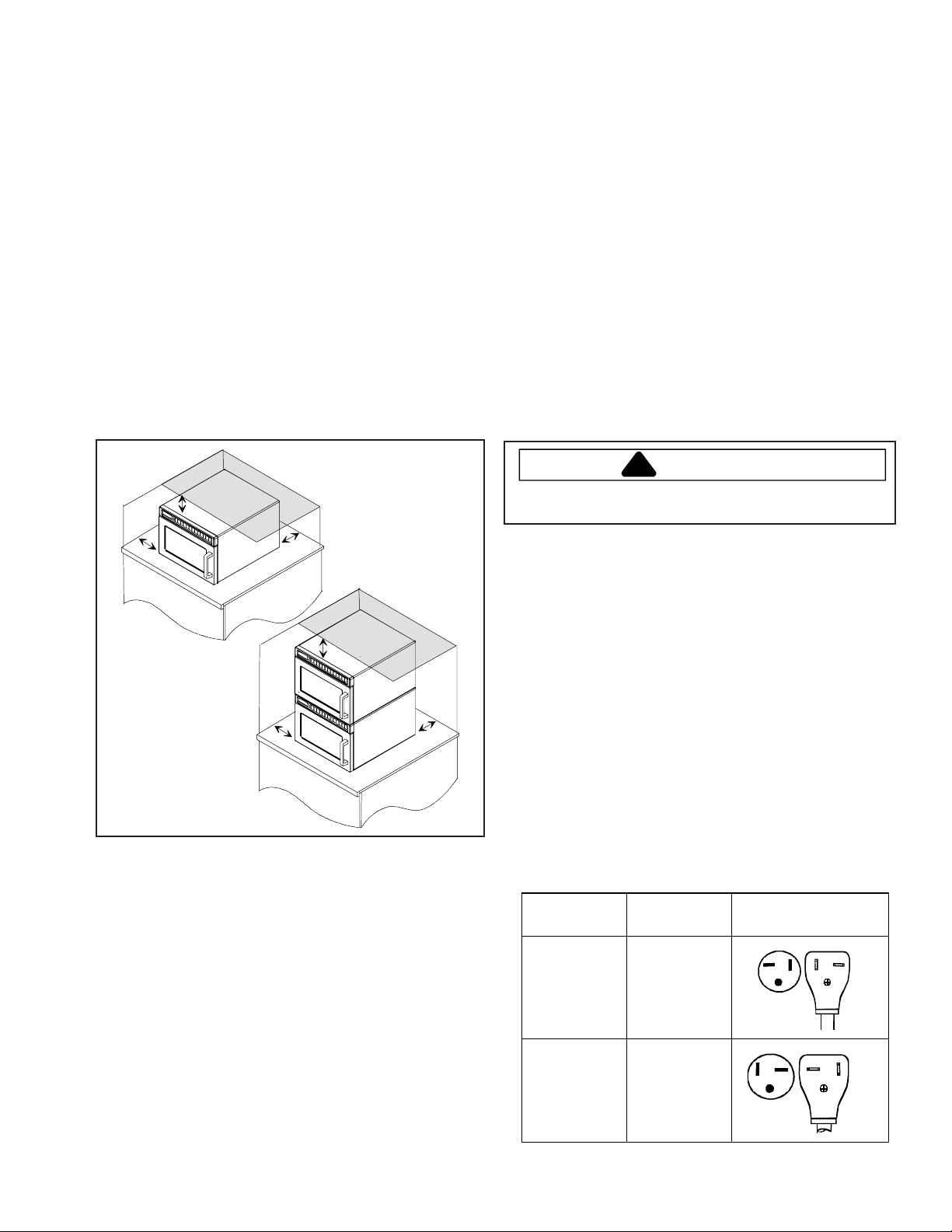
A—Allow at least 7" (17.8 cm) of clearance around top
and sides of oven. Proper air flow around oven cools
electrical components. With restricted air flow, oven
may not operate properly and life of electrical parts
is reduced.
B—Allow at least 2 9/16" (6.5 cm) between air discharge
on back of oven and back wall.
B
A
A
B
This equipment MUST be grounded. In the event of an
electrical short circuit, grounding reduces risk of electric
shock by providing an escape wire for electric current.
This oven is equipped with a cord having grounding wire
with a grounding plug. Plug must be plugged into an
outlet that is properly installed and grounded. DO NOT
use a two-prong adapter .
Consult a qualified electrician or servicer if grounding
instructions are not completely understood, or if doubt
exists as to whether the equipment is properly grounded.
Do not use an extension cord. If product power cord is
too short, have a qualified electrician install an
appropriate receptacle. This equipment should be
plugged into a separate 60 Hz circuit with the appropriate
electrical rating as shown in the drawings. When an oven
is on a circuit with other equipment, an increase in
cooking times may be required and fuses can be blown.
Model NEMA
Designation
HDC10
HDC12
NEMA
5-20R/5-20P
120V-20AMP
Receptacle and
Plug
HDC18
HDC18SD
HDC21
9 RS2240002 Rev. 1
NEMA
6-20R/6-20P
250V-20AMP
Care and Cleaning
!
!
!
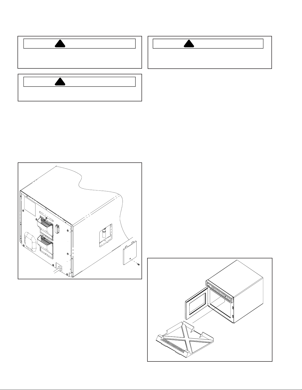
Changing Oven Light Bulb
CAUTION
T o avoid electrical shock hazard unplug power cord or
open circuit breaker to microwave oven before replacing
light bulb. After replacing light bulb, reconnect power .
CAUTION
T o avoid burns and cuts, wear gloves to protect hands
should bulb break. If hot, allow bulb to cool.
Tools and Bulb
• Protective gloves
• Standard screwdriver or ¼ inch socket
• Light bulb rated 120 volt, 25 watt
1. Unplug oven.
2. Remove screw from side of oven and remove access
cover.
Cleaning Interior , Exterior, and Door
WARNING
T o avoid electrical shock which can cause severe
personal injury or death, unplug power cord or open
circuit breaker to oven before cleaning.
Clean microwave oven with mild detergent in warm water
using soft sponge or cloth. Wring sponge or cloth to
remove excess water before wiping equipment. If desired,
boil a cup of water in microwave oven to loosen soil
before cleaning.
• Do not use abrasive cleansers or cleaners containing
ammonia. These could damage finish.
• Never pour water into microwave oven bottom.
• Do not use water pressure type cleaning systems.
Cleaning Splatter Shield
Splatter shield keeps top of microwave oven cavity and
antenna from becoming soiled. Clean soil from shield
with damp cloth or clean with mild detergent and water .
Remove splatter shield for easy cleaning.
1. Unplug oven before removing splatter shield to stop
antenna from rotating.
2. Place fingers behind shield, pull forward, and down.
• When removing and replacing splatter shield, be
careful not to bend antenna.
3. Wash shield in hot, soapy water . Rinse and
dry thoroughly .
• Do not wash splatter shield in dishwasher.
• Do not use abrasive cleaners.
4. Reinstall splatter shield by placing front portion of the
shield in first. Lift until shield slides into holes
located in back of oven.
3. Remove bulb by turning counterclockwise, being
careful not to burn fingers or break bulb.
• Replace with bulb rated 120 volt, 25 watt.
5. Reverse procedure to reassemble.
RS2240002 Rev. 1 10
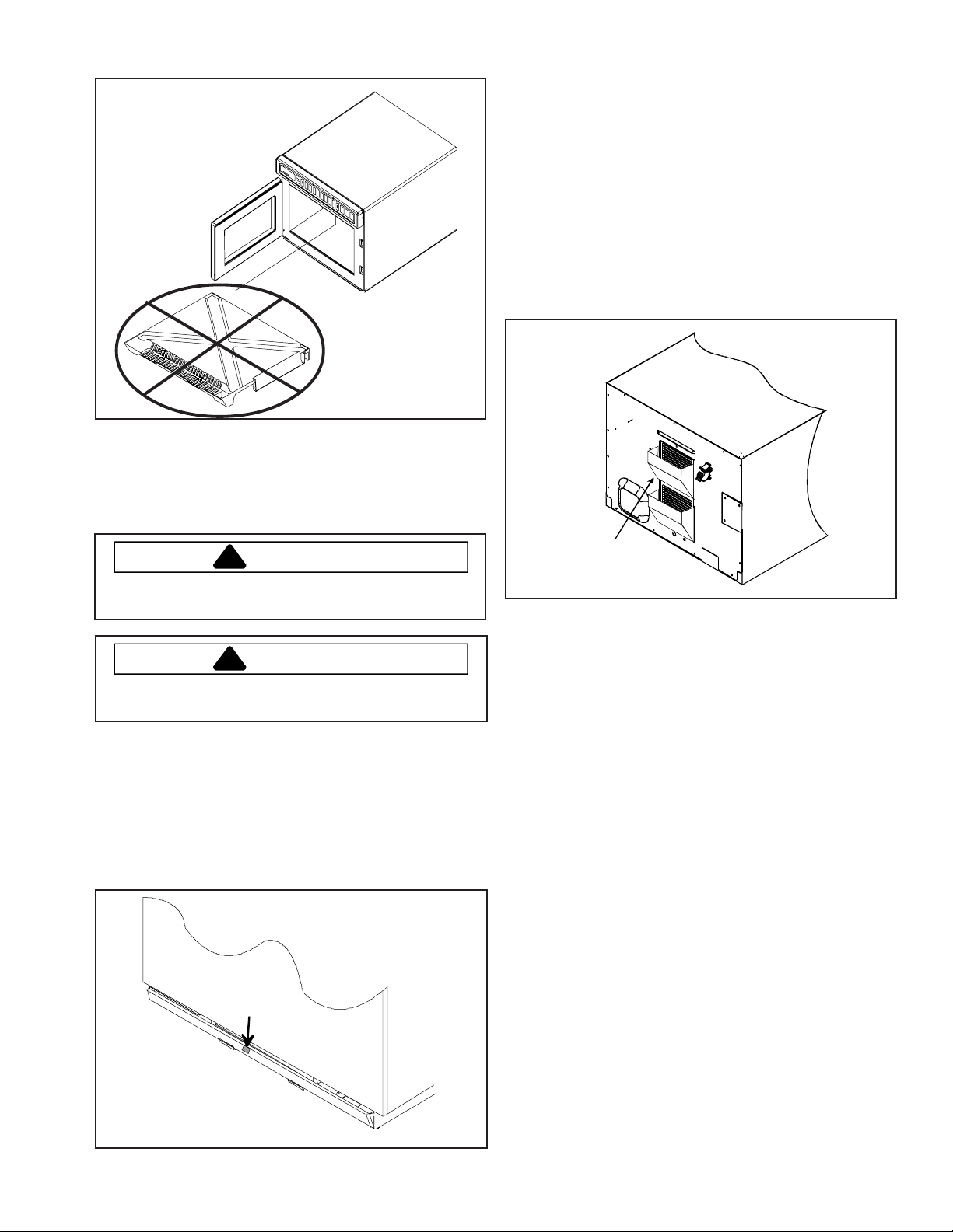
Correct Installation
!
!
Care and Cleaning
Incorrect Installation
(Shield in upside down)
NOTE: If splatter shield is installed upside down, shield
will interfere with antenna movement.
Cleaning Air Intake Filter
To replace filter
• Place bottom portion of filter into position first and push
in on the top portion of the filter, until filter is securely in
place.
NOTE: When placing filter back into position, verify
plastic tab is on the outside of the unit.
Cleaning Discharge Air V ents
Check for a buildup of cooking vapors along discharge
louvers in back of oven. Clean air vent with damp cloth to
ensure proper airflow . Dry thoroughly.
CAUTION
T o avoid overheating and oven damage, clean air filter
regularly.
CAUTION
T o avoid oven door damage, do not lift oven by oven
door.
Filter is located below oven door. Clean air intake filter
weekly for proper air flow. W ash filter in hot water and
mild detergent. Do not use oven without filter in place.
To remove filter
• Locate plastic tab in the center of filter and pull
downward (rolling the filter), to release filter from metal
holding tabs.
Plastic
Discharge
air vent
tab
11 RS2240002 Rev. 1
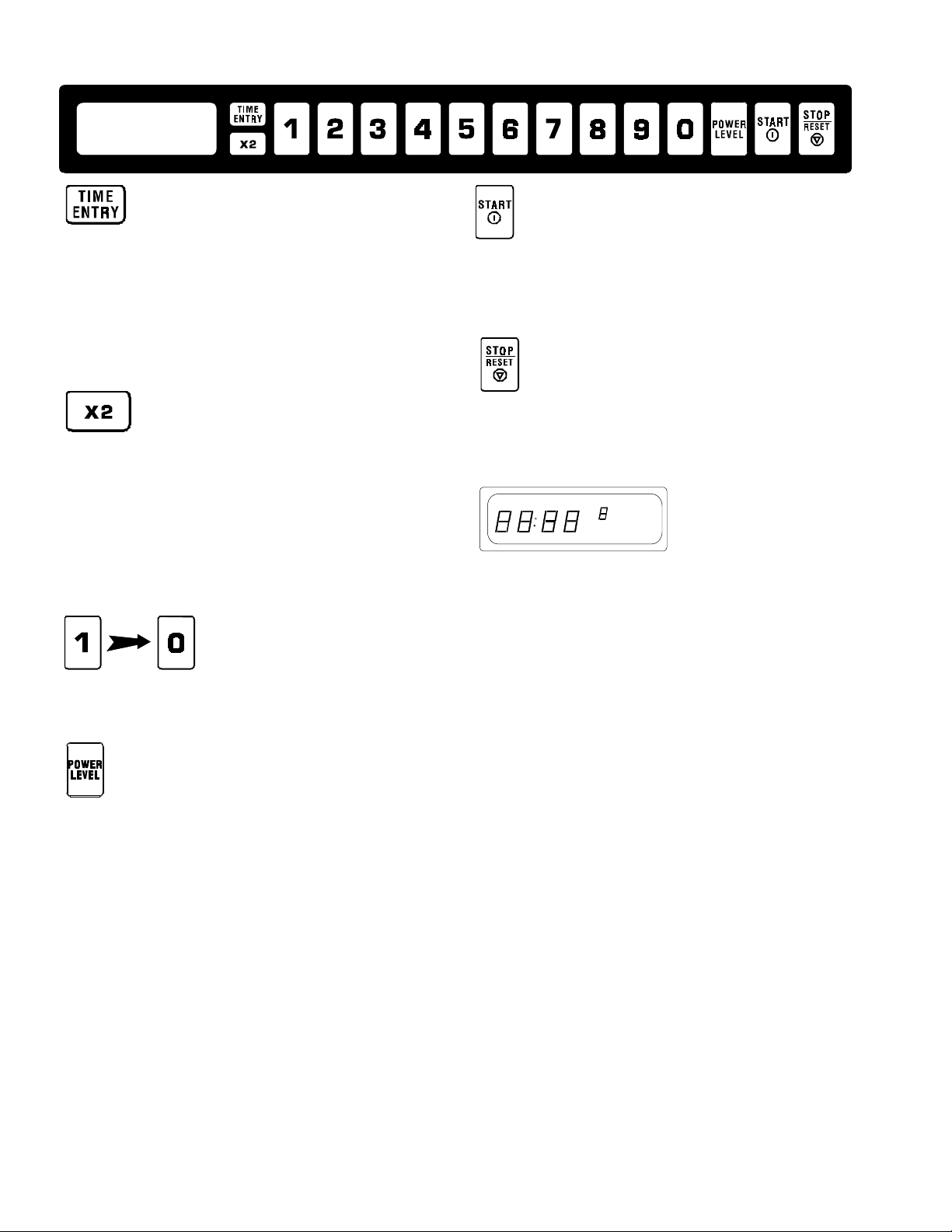
Control Panel Features
TIME ENTRY pad is used to enter cooking time for
either manual entry or programming. Cooking time
ranges from 1 second (00:01) to a total of 60 minutes
(60:00) over four stages. If more than 60 minutes of total
microwave cooking time is required, open door and
inspect food before beginning new cooking cycle.
X2 pad increases the cooking time when cooking more
than one item at a time is necessary . The amount of
added time when the X2 pad is pressed is a percent of
the original preprogrammed cooking time. The percent
can be set from 10% to 100% with the default at 80%.
The percent of the time added can be changed for
individual cooking sequences.
Numbered pads begin cooking programs or enter times
and power levels for “Manual Time Entry” cooking.
ST ART pad begins Manual T ime Entry cooking or
restarts an interrupted cooking cycle. When
programming, use to save time and power level, and to
advance to next user option.
STOP/ RESET pad exits programming mode and stop
cooking during cooking cycle.
MICRO DEFR WARM MEDHI POWER HOLD
COOK
LEVEL
TIMER
READY
CLOCK
DisplaySome items in display can be seen but will not
glow.
Stages
This oven can be programmed to run 4 cooking
sequences consecutively . Each sequence is called a
stage. For example, the first cycle could be programmed
to defrost at 60% power, the second to defrost at 30%
power, the third to heat at 100% power , and the fourth to
hold warm at 10% power. Total time for all cooking
stages counts down.
POWER LEVEL pad is used to set microwave power
level. When cooking, the power level can be decreased
for foods that require slower more even cooking.
Microwave power levels range from 0% to 100% in 10%
increments. If cooking time is set and ST ART pad
pressed, oven cooks at 100% power. When
programming, to reset power level to 100%, press
POWER LEVEL pad.
RS2240002 Rev . 1 12
User Options
User Options allow the user to program the oven to
perform in a way convenient to the user . The beeps,
maximum cooking time, and number of preprogrammed
cooking sequences can be changed.

Displays
Cooking Methods
Memory Pads
This oven can of store either 10 or 100 cooking programs
in memory .
Single Pad Cooking
From the factory , it is programmed to store 10 cooking
programs. Each pad begins a cooking program.
Double Pad Cooking
The oven control can be changed to store up to 100
cooking programs. T o set the control to 100 cooking
programs, see the “User’s Options” section of this
manual. T o heat when the oven is set for 100 programs ,
press 2 memory pads. For example, to start the first
program, press pad 0, then pad 1. T o use the second
program, press pad 0, then pad 2. After the pads are
pressed, the oven starts automatically and time counts
down.
Manual Time Entry
Manual Time Entry feature allows the operator to heat
without changing the preprogrammed pads. Time must be
entered and power can be set before cooking. ST ART pad
must be pressed to begin cooking.
Programming Displays
MICRO DEFR WARM MEDHI POWER HOLD
This display indicates oven is in programming mode and
ready to program a numbered pad(s).
MICRO DEFR WARM MEDHI POWER HOLD
This display indicates oven is set to double pad entry and
2 pads must be pressed to enter a program. See
“Programming” section of manual for programming
procedure or “User Options” to change from single or
double pad entry .
MICRO DEFR WARM MEDHI POWER HOLD
COOK
LEVEL
COOK
LEVEL
COOK
LEVEL
TIMER
READY
CLOCK
TIMER
READY
CLOCK
TIMER
READY
CLOCK
Cooking Displays
MICRO DEFR WARM MEDHI POWER HOLD
READY shows when oven control will accept entries.
MICRO DEFR WARM MEDHI POWER HOLD
25:20 shows cooking time. When more than one cooking
stage is programmed, total time for all stages displays.
POWER Shows when microwave energy is generated.
COOK LEVEL shows when oven is operating. 8 indicates
the microwave power level used. If number does not
show, oven is cooking at 100% power .
COOK
LEVEL
COOK
LEVEL
TIMER
READY
CLOCK
TIMER
READY
CLOCK
This display shows briefly when programming more than
one stage. It indicates programming mode for pad 02.
The smaller “1” indicates stage 1 is being programmed.
MICRO DEFR WARM MEDHI POWER HOLD
COOK
LEVEL
TIMER
READY
CLOCK
This display indicates programming user options mode.
See “User Options” section of manual for programming
procedure.
MICRO DEFR WARM MEDHI POWER HOLD
COOK
LEVEL
TIMER
READY
CLOCK
This display indicates cooking factor of 80% when X2 pad
is pressed.
13 RS2240002 Rev . 1

Operation
Interrupting Operation
Open oven door or press
operation. Display continues to show countdown time.
Close door and press
operation.
STOP/RESET
ST ART
pad to resume oven
pad to interrupt
Canceling Mistakes
If oven is not cooking, press
display . If oven is cooking, press
once to stop oven, then again to clear display . If oven
door is open and time shows in display, close oven door
and press
STOP/RESET
STOP/RESET
pad to clear
STOP/RESET
pad to clear display .
pad
Operating Preprogrammed Pads
From the factory , this oven can of store up to 10
preprogrammed cooking sequences in memory . To heat
using a preprogrammed sequence, press a numbered
pad. Oven starts to heat automatically . Example: Heat
using the third cooking sequence.
1. Open oven door, place food in oven, and close oven
door.
• Display shows “READY”.
• If pad is not pressed in 60 seconds, open and
close oven door again.
2. Press 3 pad.
• Oven operates and time counts down.
• Display shows cooking time, “POWER”, ”COOK
LEVEL”. Display shows “POWER” only when
microwave energy is present.
• If power level other than 100 percent power was
programmed, display shows “COOK LEVEL” and
power level.
• If additional cooking time is required, press
preprogrammed pads before or after cooking cycle
ends.
3. Oven stops cooking and oven signal sounds when
cooking timing elapses.
Preprogrammed Times and Cook Level
All preprogrammed pads arrive set at full power.
Pads Times Pads Times
1 10 sec . 6 1:30 min.
2 20 sec. 7 2 min.
3 30 sec. 8 3 min.
4 45 sec. 9 4 min.
5 1 min. 0 5 min.
Double Pad Programs
The oven control can be changed to store up to 100
cooking programs. See the “User’s Options” section of
this manual to change oven control.
T o start a double pad cooking program, press 2 memory
pads. For example, press pad 0 and pad 3 to start a
cooking program.
Using X2 Pad
X2 pad increases the cooking time when cooking more
than one item at a time is necessary . The amount of
added time when the X2 pad is pressed is a percent of
the original preprogrammed cooking time. The percent
can be set from 10% to 100% with the default at 80%.
The percent of the time added can be changed for
individual cooking programs.
Press X2 pad before pressing memory pad. For example,
press X2 pad and then memory pad 3. Pad 3 normally
cooks for 30 seconds. When the X2 pad is pressed
before memory pad 3, 54 seconds displays because it
added 24 seconds, (80% of 30 sec. =24 sec.).
Manual Time Entry
Manual Time Entry feature allows the operator to enter
time and power levels, and heat without changing the
preprogrammed pads. Example: Heat for 30 seconds at
80% power.
1. Open oven door, place food in oven, and close door .
• Display shows “READY”. Fan and light operate.
• If pad is not pressed in 60 seconds, open and
close oven door again.
2. Press TIME ENTRY pad.
• Display shows “0000” and “READY”.
3. Press 3 and 0 pad to enter cooking time.
4. Press POWER LEVEL pad to change power level.
• Display shows “COOK LEVEL” and current power
level if other than 100 percent power.
5. Press 8 pad to enter desired power level.
6. Press STAR T pad.
• Oven operates and time counts down.
• Display shows cooking time, “POWER”, “COOK
LEVEL”.
• Display shows “POWER” only when microwave
energy is present.
• If power level other than 100 percent power was
programmed, display shows “COOK LEVEL” and
power level. Display counts down cooking time.
7. Oven stops cooking and oven signal sounds when
cooking timing elapses.
RS2240002 Rev . 1 14

Programming Instructions
Memory Pads
From the factory , this oven can of store up to 10 cooking
programs. Follow instructions below to program cooking
times and power levels for customized cooking.
Example: Program third cooking sequence to heat for 30
seconds at 80% power.
1. Open oven door.
• Display shows “READY”.
• If door is closed or RESET pad is pressed before
finishing programming sequence, oven exits
programming mode.
2. Press and hold pad 1 for approximately 5 seconds.
• After 5 seconds, signal sounds. Display shows
“P:0”.
3. Press 3 pad to select memory pad.
• Display shows cooking time, “COOK LEVEL” and
power level if other than 100 percent power.
4. Press 3 and 0 pad to enter desired cooking time.
5. Press POWER LEVEL pad to change power level.
• Display shows “COOK LEVEL” and current power
level if other than 100 percent power.
6. Press 8 pad to enter desired power level.
7. Press ST ART pad to save new cooking time and
power level in oven memory.
• Display shows “P:0”.
• Repeat step 3–8 to program additional pads.
8. Press STOP/RESET pad or close oven door to exit
programming mode.
Double Pad Programs
The oven control can be changed to store up to 100
cooking programs. See the “User’s Options” section of
this manual to change oven control.
T o create a double pad program, follow the instructions
above except for a change to step #3. When entering the
cooking program number, press 2 memory pads. For
example, press pads 0 and pad 3 to create a new
cooking program.
Multiple Cooking Stages
Follow instructions below to program oven to perform four
consecutive cooking cycles without interruption.
Example: Program third cooking sequence to heat for 30
seconds at 80% power, 40 seconds at 50% power , and
10 seconds at 100% power.
1. Open oven door.
• Display shows “READY”.
• If door is closed or RESET pad is pressed before
finishing programming sequence, oven exits
programming mode.
2. Press pad 1 for approximately 5 seconds.
• After 5 seconds, signal sounds. Display shows
“P:0”.
4. Press 3 pad to select memory pad.
• Display shows cooking time, “COOK LEVEL” and
power level if other than 100 percent power.
5. Press 3 and 0 to enter desired cooking time.
6. Press POWER LEVEL pad to change power level.
• Display shows “COOK LEVEL” and current power
level if other than 100 percent power.
7. Press 8 pad to enter desired power level.
8. Press TIME ENTRY pad.
• Display briefly shows "P:03
programming, pad 3, stage 2. Then cook time and
power level for stage show in display .
• Repeat steps 5–8 to create additional stages.
9. Press ST ART pad to save new cooking time and
power level in oven memory .
10.Press STOP/RESET pad or close oven door to exit
programming mode.
(1-4)
" indicating
X2 Quantity Feature
This feature allows the user to change the amount of time
added when the X2 pad and then the programmed pad is
pressed. Based on the original time, the X2 pad can add
from 10%-100% of additional cooking time. The default is
80%. Example: change cooking factor to 50% for third
cooking sequence.
1. Open oven door.
• If door is closed or
finishing programming sequence, oven exits
programming mode.
2. Press and hold pad 1 for approximately 5 seconds.
• After 5 seconds, signal sounds. Display shows
“P:--”.
3. Press 3 pad to select the cooking program.
4. Press 5 pad to change cooking factor.
• Display shows “CF:05”.
5. Press ST ART pad to save changes.
6. Press STOP/RESET pad or close oven door to exit
programming mode.
Double Pad Programs
The oven control can be changed to store up to 100
cooking programs. See the “User’s Options” section of
this manual to change oven control.
T o change the quantity for a double pad program, follow
the instructions above except for a change to step #3.
When entering the cooking program number , press 2
memory pads. For example, press pads 0 and pad 3 to
create a new cooking program. After the program is
saved, press pad 0 and pad 3 to start a cooking program.
RESET
pad is pressed before
15 RS2240002 Rev . 1

Programming Instructions
User Options
Follow the instructions below to customized the
microwave oven’s operation. End-of-cycle signal,
maximum cooking time and other options can be
changed to meeting your cooking needs. Example:
Change setting to single digit pad operation.
1. Open oven door.
• If door is closed or
finishing programming sequence, oven exits
programming mode.
2. Press and hold pad 2 for approximately 5 seconds.
• After 5 seconds, signal sounds. Display shows
“0P:”.
Numbered Pads Display Options (Factory Settings in Bold)
1
End of Cycle Beep
2
Speaker Volume
3
Key Beep
4
Keyboard Enable
Window
5
Add Time during
Heating
6
Reset Door Open
7
Maximum Heating
Time
RESET
OP:10
OP:11
OP:12
OP:20
OP:21
OP:22
OP:23
OP:30
OP:31
OP:40
OP:41
OP:42
OP:43
OP:50
OP:51
OP:60
OP:61
OP:70
OP:71
pad is pressed before
3 second continuous beep.
Continuous beep until door is opened.
5 beeps bursts until door is opened.
Eliminates beep.
Sets volume to low.
Sets volume to medium.
Sets volume to high.
Prevents beep when pad is pressed.
Allows beep when pad is pressed.
15 seconds after oven door is opened, keyboard disabled.
30 seconds after oven door is opened, keyboard disabled.
1 minute after oven door is opened, keyboard disabled.
2 minutes after oven door is opened, k eybo ar d dis abled.
Prevents adding heating time while oven is heating.
Allows he a t i ng time to be chang e d whi le ov e n is he a t i ng
when a memory pad is pressed.
Allows oven to resume heating time countdown after door is
opened during cycle.
Cancels heating time countdown after door is opened during cycle.
Allows 60 minutes of heating time.
Allows 10 minutes of heating time.
3. Press 9 pad.
• See table for options.
• Displays shows “OP:91”.
• “OP” represents optional program mode, first
number represents option number and second
number represents functions currently selected for
option.
4. Press 9 pad repeatedly to change setting.
5. Press ST ART pad to save changes.
• Repeat steps 3-5 to change additional options.
• Changes appear after door is closed or STOP/
RESET is pressed.
6. Press STOP/RESET pad or close oven door to exit
programming mode.
8
Manual Operation
9
Double Digit
Operation
RS2240002 Rev . 1 16
OP:80
OP:81
OP:90
OP:91
Allows use of preprogrammed pads only.
Allows use of manual time entry and preprogrammed pads.
Allows 10 (0-9) preprogrammed pads.
Allows 100 (00-99) preprogrammed pads.
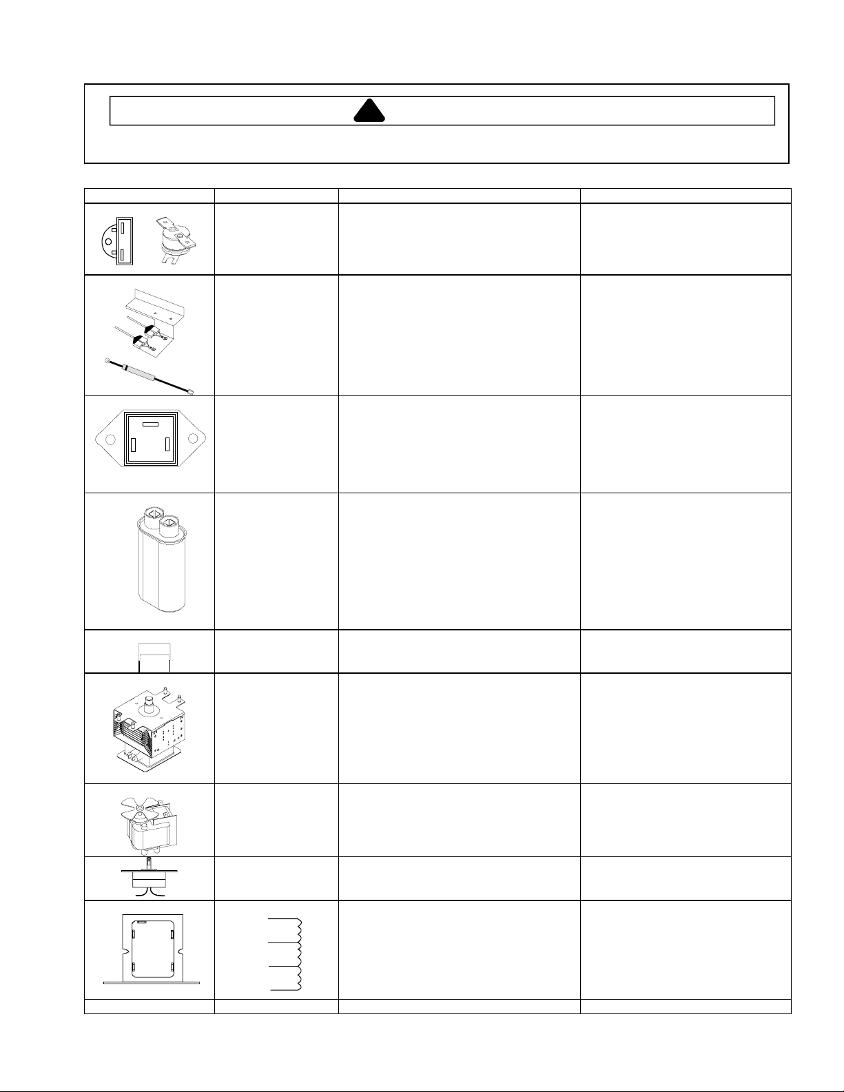
Component Testing Procedures
!
WARNING
To avoid risk of electrical shock, personal injury, or death, disconnect power to oven and discharge capacitor
before servicing, unless testing requires it.
Illustration Component Testing Results
Thermal Cutout Disconnect all wires from TCO.
Diode Assembly
Measure resistance across terminals.
Cavity Thermal Fuse
Magnetron TCO
Discharge Capacitors
Remove diode lead from capacitor and
connect ohmmeter.
Reverse leads for second test.
Open at 219°F (104°C)
Open at 280°F (138°C) and closed at
180°F (82°C)
Infinite resistance should be
measured in one direction and 50K
or more in the opposite direction.
NOTE:
Analog meter must contain a
battery of 6 volts minimum.
Ω
Triac Disconnect wires to triac.
MT2
MT1 GATE
Capacitor
Snubber Assembly Disconnect wires to snubber.
Magnetron
Blower Motor Remove all wires from motor.
Measure resistance from:
MT1 to MT2
MT1 to Gate
MT2 to Gate
All terminals to ground
Discharge Capacitors
Remove wires from capacitor terminals and
connect ohmmeter, set on highest
resistance scale to terminals.
Also check between each terminal and
capacitor case.
Measure resistance across terminals. Infinite
Discharge Capacitors
Remove wires from magnetron and connect
ohmmeter to terminals. Also check
between each terminal and ground.
Caution - Do not operate oven with
wire to terminal MT2 removed.
Infinite
Approximately 40 Ω or more
Infinite
Infinite
Between Terminals: Meter should
momentarily deflect towards zero
then return to over 5 MΩ. IF no
deflection occurs, or if continuous
deflection occurs, replace capacitor.
Terminal to Case: Infinite resistance
Between Terminals: Less than 1
Each terminal to ground measures
Infinite resistance.
Note:
This test is not conclusive. If
oven does not heat and all other
components test good replace the
magnetron and retest.
Ω
Measure resistance across coil.
Antenna motor Remove all wires from motor.
Auto Transformer
230
COM
120
Wire Harness Test continuity of wires. Indicates continuity
208
230
208
120
0
Discharge Capacitors
Remove all wires from terminals.
Measure resistance from:
230 to 0
208 to 0
120 to 0
RS2240002 Rev. 1 17
Measure resistance across terminals.
Approximately 30
Circuitry
120 VACApproximately 3.4 K
230 VACApproximately 12 K
42.4
Ω
38.6
Ω
21.5
Ω
Ω
Ω
Ω
Component Testing Procedures
!
WARNING
To avoid risk of electrical shock, personal injury, or death, disconnect power to oven and discharge capacitor
before servicing, unless testing requires it.
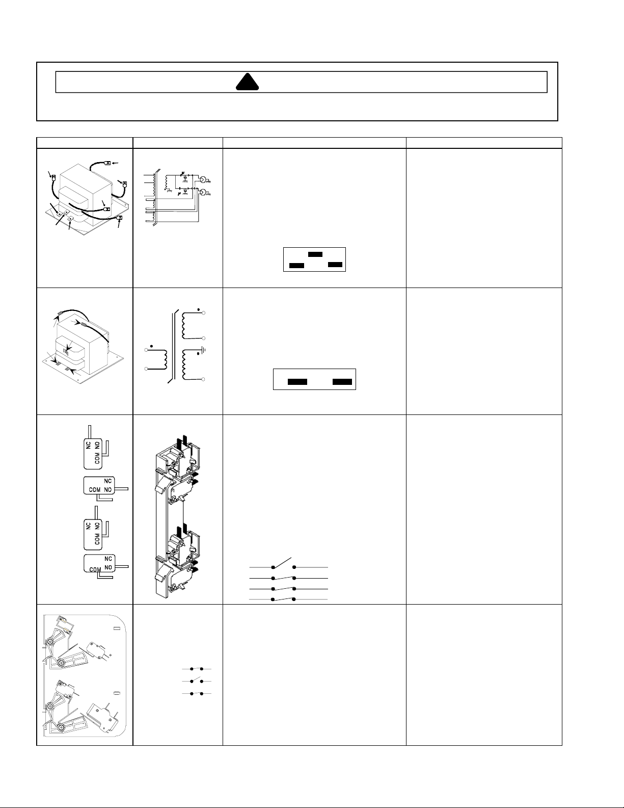
Illustration Component Testing Results
5
8
7
Transformer
# 4
# 1
# 3
# 2
# 5
# 6
# 7
# 8
1.0 F
HDC21,
HDC18SD,
HDC18
CRC18T2OG
CRC21T2RL
Transformer
1
2
1.0 F
-300 MA
-300 MA
Discharge Capacitors
Remove all wires from terminals.
Measure resistance from:
Terminal 1 to 2
Terminal 1 to 3
Terminal 5 to 6
Terminal 7 to 8
Terminal 4 to Ground screw on transformer
Terminal 4 to any other terminal
Violet
3
12
Gray
Red
Discharge Capacitor
Remove all wires from terminals, and
5
measure resistance from:
Terminal 1 to 2
Terminal 5 to 6
6
Terminal 4 to Ground screw on transformer
Terminal 4 to any other terminal
4
2
1
Gray Red
1.0
Ω
Less than 1
Less than 1
Less than 1
30
Ω
Ω
Ω
Ω
Infinite resistance should be
indicated, if not replace transformer.
Less than 1
Less than 1
78
Ω
Ω
Ω
Infinite resistance should be
indicated, if not replace transformer.
12136102
6
5
4
−
HDC10
−
HDC12
1
4
1
3
2
Terminal 1− 230 V
Terminal 2− Common
Terminal 3−208 V
10426609
10426610
6
2
Terminal 1−120 V
Terminal 2−Common
R0150154
Monitor
Primary
Logic
Secondary
12538901Q
Monitor
Primary /
Logic
Seconda ry
Interlock switch
assembly
Interlock switch
assembly
Door Closed
Primary / Logic
Monitor
Secondary
C
C
C
Disconnect wires to switch.
With door open measure resistance from:
Terminal C to NC Monitor
Terminal C to NO Primary
Terminal C to NO Logic
Terminal C to NO Secondary
With door closed measure resistance from:
Terminal C to NC Monitor
Terminal C to NO Primary
Terminal C to NO Logic
Terminal C to NO Secondary
Door Closed
NC
NO
NO
NO
Monitor
Primary
Logic
Secondary
C
C
C
C
Disconnect wires to switch.
With door open measure resistance from:
Terminal C to NC Monitor
Terminal C to NO Primary
Terminal C to NO Logic
NO
Terminal C to NO Secondary
NC
With door closed measure resistance from:
NO
Terminal C to NC Monitor
Terminal C to NO Primary
Terminal C to NO Logic
Terminal C to NO Secondary
Indicates continuity
Infinite
Infinite
Infinite
Infinite
Indicates continuity
Indicates continuity
Indicates continuity
Indicates continuity
Infinite
Infinite
Infinite
Infinite
Indicates continuity
Indicates continuity
Indicates continuity
RS2240002 Rev. 118
 Loading...