


RV Radiant Cooktop Installation Instructions (Models AEZ8590 & AEZ8581)
IMPORTANT:
Installer: Leave installation instructions with the appliance.
•Follow the enclosed instructions to avoid countertop laminate damage. Owner: Keep installation instructions for future reference.
•Save installation instructions for local electrical inspector’s use.
•Only qualified personnel should install or service this appliance.
•Read “Safety Instructions” in Use & Care Guide before using this appliance.
 WARNING
Improper installation, adjustment, alteration, service,
maintenance or use of this appliance can result in serious
injury or property damage.
 CAUTION
Warranty is void on equipment installed other than as
recommended by manufacturer.
1. UNPACK THE COOKTOP
Remove the cooktop from the carton and place it upside down over two soft pads, making sure control knobs do not interfere with any surface.
electrical rating data plate
 CAUTION
Never use a metal blade to pry off knobs. If a knob cannot be
easily removed, tuck folds of a dishtowel under the knob skirt
and pull upward with steady, even pressure.
2. DETERMINE PLACEMENT
Determine where the unit will be installed to conform with all safety codes and the guidelines below. Unit may be safely installed as near as 2" (5.08 cm) from any cabinet or wall if space limitations require.
Installing cabinetry over the cooktop:
1.To eliminate the risk of burns or fire by reaching over heated surface units, cabinet storage space located above the surface units should be avoided.
2.If cabinet storage is to be provided, the risk can be reduced by installing a range hood that projects horizontally a minimum of 5" (12.7 cm) beyond the bottom of the cabinets.
3.A clearance of 30" (76.2 cm) minimum is required between the top of the cooktop and the bottom of an unprotected wood or metal cabinet.
4.A clearance of 18" (45.72 cm) minimum is required when the bottom of a wood or metal cabinet is protected by not less than 1/4" (0.635 cm) FLAME RETARDANT millboard covered with not less than No. 28 MSG sheet steel, 0.015" (0.28 cm) stainless steel or 0.024" (0.061 cm) aluminum or copper.
CLEARANCE DIMENSIONS
5"
(12.7 cm)
3
(76.2 cm)
1 |
|
(45.72 cm) |
2" |
|
|
mi |
(5.08 cm) |
lea |
|
around cooktop to |
|
cabinets or walls |
|
3. PROVIDE CUTOUT
After determining correct cooktop position using the guidelines, make the cutout in the counter top (Refer to illustrations).
 CAUTION
Cutout dimensions are critical. Dimensions must be
measured and cut accurately to within ± 1/16" (.16 cm) to
insure proper fit.
Cutout:
1.Chamfer all exposed edges of decorative laminate to prevent damage from chipping.
2.Radius corners of cutout and file to insure smooth edges and prevent corner cracking.
3.Rough edges, inside corners which have not been rounded and forced fits can contribute to cracking of the countertop laminate.
4.Countertop must be supported within 3" (7.62 cm) of cutout.
NOTE: Countertop must be flat below the cooktop from the cutout to the edge of the glass. 13/16" is the distance from the edge of cooktop glass to the edge of the cutout.
TWO-ELEMENT RADIANT COOKTOP DIMENSIONS
22 3/4" |
13 3/4" |
57.8 cm |
34.9 cm |
2 7/8" 
7.3 cm
12 3/8"
31.4 cm
3 1/2" |
21 3/8" |
8.9 cm |
|
|
54.3 cm |
21/2" 
6.4cm
NOTE: Figures may not be representative of actual unit
8101P717-60
(09-31-05)
4. INSTALL THE COOKTOP
•Place the unit in the cutout.
•Remove screws from bottom of cooktop and install brackets to the bottom of the unit.
•Secure the cooktop to the countertop by tightening the adjusting screws until finger tight. DO NOT OVER-TIGHTEN.
 CAUTION
Do not over-tighten the hold down adjusting screw. Damage
to the glass cooktop will occur if excessive pressure is used.
Secure the unit to the countertop using only the hold down
bracket and adjusting screw provided, do not use any other
means to secure the unit.
NOTE: Foam tape is supplied with the unit. If desired, apply the foam tape around the bottom outside edge of the glass before installing unit.
foam tape 
adjusting screws
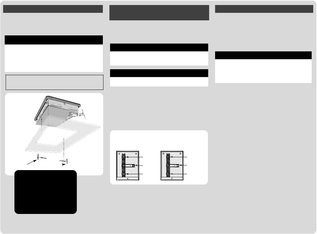
5. MAKE ELECTRICAL CONNECTION
•Check that the power supply is OFF.
•Make electrical connection to the unit.
•Consult local codes for proper power hookup.
•The supply voltage may be varied according to the rating plate (located on the bottom of the unit).
 CAUTION
Do not use the junction box for additional wiring connections.
Do not remove the center terminal ground wire from the unit.
 WARNING
Turn off power supply when making electrical connections.
Model AEZ8590 (8581)
A two-wire, single phase, A.C. 120/240 volt (120 volt for Model AEZ8581) 60 cycle electrical system (properly circuit protected to meet Local Codes of ANSI/NFPA No. 70) must be provided. Unit must be properly grounded in accordance with local wiring code. The supply ground wire should be connected to the green grounding screw on the power block grounding tab. There is no neutral wire on the AEZ8590. Recommended minimum wire size is 12 AWG.
Model AEZ8590 |
Model AEZ8581 |
(240 Volt, 13.3 Amps) |
(120 Volt, 20 Amps) |
Red |
White/Neutral |
Ground |
Ground |
Black |
Black |
This unit is supplied with an electrical junction box on a 48" long, 1/2" (1.3 cm) I.D. flexible conduit. The junction box is designed to be attached to a solid mounting surface in the area below the cooktop. Connect all supply wires to the power block with approved connectors. Bare wires can be attached using the supplied bare wire adapter lugs. All connections should be torqued to 20 in-lb.
6. TEST THE UNIT
•Restore the power supply and test to insure control knobs operate all elements properly.
Marine and RV Installation
Utensil Retention Device:
This unit does not include sea rails or other devices to stabilize or secure cooking pots or utensils. Pot retention devices must be used to secure items to the cooktop.
 CAUTION
Cookware retention devices must be installed and used
properly to minimize the potential for spills and burns.
Extreme caution should be exercised when cooking in a
moving boat or vehicle.
Marine Wiring:
In marine applications, ABYC 826, E-11, AC&DC Electrical Systems, should govern cooktop installation.
You must provide an adequate electrical supply system as required for your cooktop. All wire connections must be in accordance with local codes and properly insulated. Check with local utility for governing electrical codes and ordinances. In the absence of local electrical codes, the National Electrical Code (NEC), ANSI/NFPA No. 70-latest edition, governing electric range installations must be followed. A copy of the National Electrical Code, ANSI/NFPA No. 70-latest edition can be obtained by writing to:
National Fire Protection Association
Batterymarch Park
Quincy, MA 02269
IMPORTANT: The installation of a cooktop designed for mobile home installation must conform with the Manufactured Home Construction and Safety Standard, Title 24 CFR, Part 3280 (formerly the Federal Standard for Mobile Home Construction and Safety, Title 24 HUD, Part 280) or, when such standard is not applicable, the Standard for Manufactured Home Installations ANSI A225.1/NFPA501A, or with local codes. In Canada the range must be installed in accordance with the current CSA Standard C22.1 - Canadian Electrical Code Part1.
Maytag • 403 West Fourth Street North • P. O. Box 39 • Newton, Iowa 50208
 Loading...