


 Loading...
29" (737 MM) GAS DRYER INSTALLATION INSTRUCTIONS
INSTRUCCIONES DE INSTALACIÓN
PARA LA SECADORA A GAS DE 29" (737 MM)
TableofContents/Índice
DRYER SAFETY....................................... |
1 |
INSTALLATION INSTRUCTIONS ........... |
4 |
Tools and Parts...................................... |
4 |
Location Requirements ........................ |
4 |
Electrical Requirements......................... |
5 |
Gas Supply Requirements..................... |
6 |
Venting Requirements ........................... |
7 |
Plan Vent System .................................. |
8 |
Install Vent System ................................ |
9 |
Install Leveling Legs .............................. |
9 |
Make Gas Connection......................... |
10 |
Connect Vent....................................... |
10 |
Level Dryer........................................... |
10 |
Reverse Door Swing (Optional) ........... |
11 |
Complete Installation........................... |
12 |
SEGURIDAD DE LA SECADORA ......... |
13 |
INSTRUCCIONES DE INSTALACIÓN .. |
15 |
Herramientas y piezas ......................... |
15 |
Requisitos de localización .................. |
15 |
Requisitos eléctricos ........................... |
17 |
Requisitos del suministro de gas ........ |
17 |
Requisitos de ventilación..................... |
19 |
Planificación del sistema de |
|
ventilación............................................ |
20 |
Instalación del sistema de ventilación. 21 |
|
Instalación de las patas niveladoras ... |
21 |
Conexión del suministro de gas.......... |
22 |
Conexión del ducto de escape ........... |
22 |
Nivelación de la secadora ................... |
22 |
Cómo invertir el cierre de la puerta |
|
(opcional) ............................................. |
22 |
Complete la instalación ....................... |
23 |
DRYER SAFETY
Your safety and the safety of others are very important.
We have provided many important safety messages in this manual and on your appliance. Always read and obey all safety messages.
This is the safety alert symbol.
This symbol alerts you to potential hazards that can kill or hurt you and others.
All safety messages will follow the safety alert symbol and either the word “DANGER” or “WARNING.” These words mean:
 DANGER
 WARNING
You can be killed or seriously injured if you don't immediately follow instructions.
You can be killed or seriously injured if you don't follow instructions.
All safety messages will tell you what the potential hazard is, tell you how to reduce the chance of injury, and tell you what can happen if the instructions are not followed.
W10131643A

IMPORTANT SAFETY INSTRUCTIONS
When discarding or storing your old clothes dryer, remove the door.
SAVE THESE INSTRUCTIONS
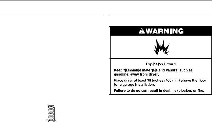
WARNING: For your safety, the information in this manual must be followed to minimize the risk of fire or explosion, or to prevent property damage, personal injury, or death.
–Do not store or use gasoline or other flammable vapors and liquids in the vicinity of this or any other appliance.
–WHAT TO DO IF YOU SMELL GAS:
•Do not try to light any appliance.
•Do not touch any electrical switch; do not use any phone in your building.
•Clear the room, building, or area of all occupants.
•Immediately call your gas supplier from a neighbor's phone. Follow the gas supplier's instructions.
•If you cannot reach your gas supplier, call the fire department.
–Installation and service must be performed by a qualified installer, service agency, or the gas supplier.
2
In the State of Massachusetts, the following installation instructions apply:
■Installations and repairs must be performed by a qualified or licensed contractor, plumber, or gasfitter qualified or licensed by the State of Massachusetts.
■If using a ball valve, it shall be a T-handle type.
■A flexible gas connector, when used, must not exceed 3 feet.
WARNING: Gas leaks cannot always be detected by smell.
Gas suppliers recommend that you use a gas detector approved by UL or CSA.
For more information, contact your gas supplier.
If a gas leak is detected, follow the “What to do if you smell gas” instructions.
3
INSTALLATION INSTRUCTIONS
ToolsandParts
Gather the required tools and parts before starting installation. Read and follow the instructions provided with any tools listed here.
■8" or 10" pipe wrench
■8" or 10" adjustable wrench (for gas connections)
■Flat-blade screwdriver
■Adjustable wrench that opens to 1" (25 mm) or hexhead socket wrench (for adjusting dryer feet)
■¼" nut driver or socket wrench (recommended)
Parts supplied:
■Level
■Knife
■Vent clamps
■Pipe-joint compound resistant to LP gas
■Caulking gun and compound (for installing new exhaust vent)
■Pliers
■Tape measure
Remove parts package from dryer drum. Check that all parts were included.
4 leveling legs
Parts needed:
Check local codes and consult gas supplier. Check existing gas supply, electrical supply and venting, and read “Electrical Requirements,” “Gas Supply Requirements” and “Venting Requirements” before purchasing parts.
Mobile home installations require special parts (listed following) that may be ordered by calling the dealer from whom you purchased your dryer. For further information, please reference the front page of the Dryer User Instructions.
■Mobile Home Installation Kit. Ask for Part Number 346764.
■Metal exhaust system hardware.
LocationRequirements
You will need
■A location that allows for proper exhaust installation. A gas dryer must be exhausted to the outdoors. See “Venting Requirements.”
■A grounded electrical outlet located within 2 ft (610 mm) of either side of the dryer. See “Electrical Requirements.”
■A sturdy floor to support the dryer and a total weight (dryer and load) of 200 lbs (90.7 kg). The combined weight of a companion appliance should also be considered.
■A level floor with a maximum slope of 1" (25 mm) under entire dryer. (If slope is greater than 1" [25 mm], install Extended Dryer Feet kit, Part No. 279810.) Clothes may not tumble properly and models with automatic sensor cycles may not operate correctly if dryer is not level.
Do not operate your dryer at temperatures below 45ºF (7ºC). At lower temperatures, the dryer might not shut off at the end of an automatic cycle. Drying times can be extended.
The dryer must not be installed or stored in an area where it will be exposed to water and/or weather.
Check code requirements. Some codes limit, or do not permit, installation of the dryer in garages, closets, mobile homes ,or sleeping quarters. Contact your local building inspector.
NOTE: No other fuel-burning appliance can be installed in the same closet as a dryer.
4
Installation Clearances
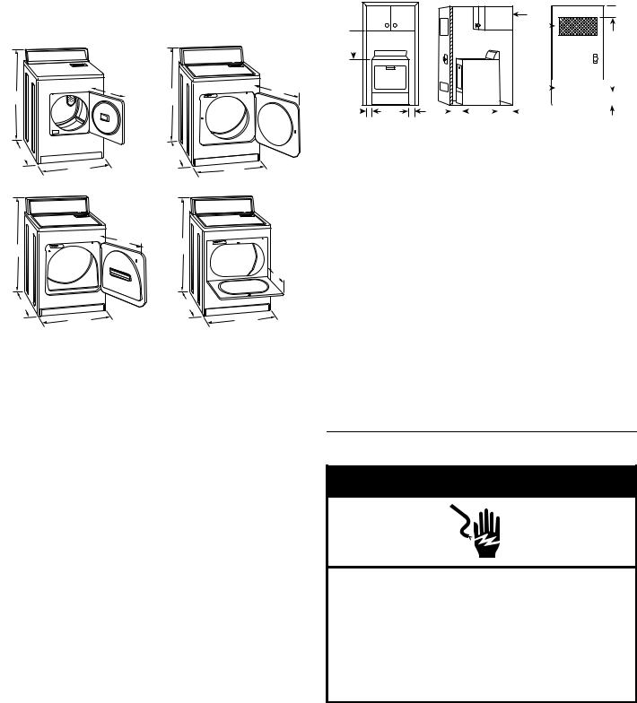
The location must be large enough to allow the dryer door to open fully.
Dryer Dimensions
|
15¼" |
22¾" |
|
(387.4mm)433/8" |
|
433/8" |
(578mm) |
|
(1100mm) |
(1100mm) |
|
|
|
*26" |
*27¾" |
(660mm) |
(705mm) |
29" |
29" |
(737mm) |
(737mm) |
A |
B |
|
22¾" |
433/8" |
(578mm) 433/8" |
(1100mm) |
(1100mm) |
|
13¾" |
|
(349mm) |
*27¾" |
*27¾" |
(705mm) |
(705mm) |
29" |
29" |
(737mm) |
(737mm) |
C |
D |
A.Small Opening Side-Swing Door
B.Large Opening Side-Swing Door
C.Wide Opening Side-Swing Door
D.Wide Opening Hamper Door
*Most installations require a minimum 5" (127 mm) clearance behind the dryer for the exhaust vent with elbow. See “Venting Requirements.”
Installation spacing for recessed area or closet installation
The following spacing dimensions are recommended for this dryer. This dryer has been tested for spacing of 0" (0 mm) clearance on the sides and rear. Recommended spacing should be considered for the following reasons:
■Additional spacing should be considered for ease of installation and servicing.
■Additional clearances might be required for wall, door, and floor moldings.
■Additional spacing should be considered on all sides of the dryer to reduce noise transfer.
■For closet installation, with a door, minimum ventilation openings in the top and bottom of the door are required. Louvered doors with equivalent ventilation openings are acceptable.
■Companion appliance spacing should also be considered.
 14"max.*
(356mm)
18"* (457 mm)
 3"* (76 mm)
48 in.2 * (310 cm )2
24 in.2 * |
|
|
|
|
|
3"* |
(155 cm )2 |
|
|
|
|
(76 mm) |
|
|
|
|
|
|||
|
|
|
|
|
|
|
1" |
|
29" |
1" |
|
|
1"* |
|
27¾" |
5"* |
|
|
|
(25 mm) |
(737 mm) |
(25 mm) (25 mm) |
(705 mm) |
(127 mm) |
||||||||
|
|
A |
|
|
|
|
|
B |
|
|
|
C |
A.Recessed area
B.Side view - closet or confined area
C.Closet door with vents
*Required spacing
Mobile Home - Additional Installation Requirements
This dryer is suitable for mobile home installations.
The installation must conform to the Manufactured Home Construction and Safety Standard, Title 24 CFR, Part 3280 (formerly the Federal Standard for Mobile Home Construction and Safety, Title 24, HUD Part 280).
Mobile home installations require:
■Metal exhaust system hardware, which is available for purchase from your dealer.
■Mobile Home Installation Kit Part #346764. See “Tools and Parts” section for information on ordering.
■Special provisions must be made in mobile homes to introduce outside air into the dryer. The opening (such as a nearby window) should be at least twice as large as the dryer exhaust opening.
ElectricalRequirements
 WARNING
Electrical Shock Hazard
Plug into a grounded 3 prong outlet.
Do not remove ground prong.
Do not use an adapter.
Do not use an extension cord.
Failure to follow these instructions can result in death, fire, or electrical shock.
5
■A 120 Volt, 60 Hz., AC only, 15or 20-amp, fused electrical supply is required. A time-delay fuse or circuit breaker is recommended. It is recommended that a separate circuit serving only this dryer be provided.
GROUNDING INSTRUCTIONS
■ For a grounded, cord-connected dryer:
This dryer must be grounded. In the event of malfunction or breakdown, grounding will reduce the risk of electric shock by providing a path of least resistance for electric current.
This dryer is equipped with a cord having an equipment-grounding conductor and a grounding plug. The plug must be plugged into an appropriate outlet that is properly installed and grounded in accordance with all local codes and ordinances.
WARNING: Improper connection of the equipment-grounding conductor can result in a risk of electric shock. Check with a qualified electrician or service representative or personnel if you are in doubt as to whether the dryer is properly grounded. Do not modify the plug provided with the dryer: if it will not fit the outlet, have a proper outlet installed by a qualified electrician.
SAVE THESE INSTRUCTIONS
GasSupplyRequirements
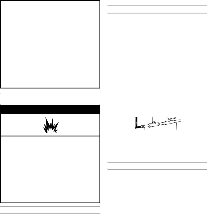
 WARNING
Explosion Hazard
Use a new CSA International approved gas supply line.
Install a shut-off valve.
Securely tighten all gas connections.
If connected to LP, have a qualified person make sure gas pressure does not exceed 13" (330 mm) water column.
Examples of a qualified person include:
licensed heating personnel,
authorized gas company personnel, and authorized service personnel.
Failure to do so can result in death, explosion, or fire.
Gas Type
Natural Gas:
This dryer is equipped for use with Natural gas. It is design-certified by CSA International for LP (propane or butane) gases with appropriate conversion.
■Your dryer must have the correct burner for the type of gas in your home. Burner information is located on the rating plate in the door well of your dryer. If this information does not agree with the type of gas available, contact your dealer or call the phone numbers referenced on the front page of the Dryer User Instructions.
LP gas conversion:
Conversion must be made by a qualified technician.
No attempt shall be made to convert the appliance from the gas specified on the model/serial rating plate for use with a different gas without consulting your gas company.
Gas Supply Line
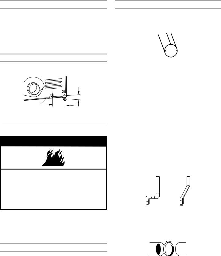
■Must include 1/8" NPT minimum plugged tapping accessible for test gauge connection, immediately upstream of the gas connection to the dryer. See illustration.
■1/2" IPS pipe is recommended.
■3/8" approved aluminum or copper tubing is acceptable for lengths under 20 ft (6.1 m) if local codes and gas supplier permit.
■If you are using Natural gas, do not use copper tubing.
■Lengths over 20 ft (6.1 m) should use larger tubing and a different size adapter fitting.
■If your dryer has been converted to use LP gas, 3/8" LP compatible copper tubing can be used. If the total length of the supply line is more than 20 ft (6.1 m), use larger pipe.
NOTE: Pipe-joint compounds that resist the action of LP gas must be used. Do not use TEFLON®† tape.
■Must include a shutoff valve:
An individual manual shutoff valve must be installed within six (6) feet (1.8 m) of the dryer in accordance with the National Fuel Gas Code, ANSI Z223.1.
The location should be easy to reach for opening and closing.
A C E
B D
A.3/8" flexible gas connector
B.3/8" pipe to flare adapter fitting
C.1/8" NPT minimum plugged tapping
D.1/2" NPT gas supply line
E.Gas shutoff valve
Gas supply connection requirements
■Use an elbow and a 3/8" flare x 3/8" NPT adapter fitting between the flexible gas connector and the dryer gas pipe, as needed to avoid kinking.
■Use only pipe-joint compound. Do not use TEFLON®† tape.
■This dryer must be connected to the gas supply line with a listed flexible gas connector that complies with the standard for connectors for gas appliances, ANSI Z21.24 or CSA 6.10.
†®TEFLON is a registered trademark of E.I. Du Pont De Nemours and Company.
6
Burner Input Requirements:
Elevations above 10,000 ft (3,048 m):
■When installed above 10,000 ft (3,048 m) a 4% reduction of the burner Btu rating shown on the model/serial number plate is required for each 1,000 ft (305 m) increase in elevation.
Gas supply pressure testing
■The dryer must be disconnected from the gas supply piping system during pressure testing at pressures greater than
½ psi.
Dryer Gas Pipe
■The gas pipe that comes out through the rear of your dryer has a 3/8" male pipe thread.
1¼" (32mm)
A9¼"
(235mm)
A. 3/8" NPT dryer pipe
VentingRequirements
 WARNING
Fire Hazard
Use a heavy metal vent.
Do not use a plastic vent.
Do not use a metal foil vent.
Failure to follow these instructions can result in death or fire.
WARNING: To reduce the risk of fire, this dryer MUST BE EXHAUSTED OUTDOORS.
IMPORTANT: Observe all governing codes and ordinances.
The dryer exhaust must not be connected into any gas vent, chimney, wall, ceiling, attic, crawlspace, or a concealed space of a building.
If using an existing vent system
■Clean lint from the entire length of the system and make sure exhaust hood is not plugged with lint.
■Replace any plastic or metal foil vent with rigid or flexible heavy metal vent.
■Review Vent system chart. Modify existing vent system if necessary to achieve the best drying performance. Only rigid or flexible metal vent shall be used for exhausting.
If this is a new vent system
Vent material
■Use a heavy metal vent. Do not use plastic or metal foil vent.
■4" (102 mm) heavy metal exhaust vent and clamps must be used. DURASAFE™ venting products are recommended.
4"
102 mm
4" (102 mm) heavy metal exhaust vent
DURASAFE™ vent products can be purchased from your dealer or the toll-free number listed on the cover of the Dryer User Instructions. For more information, see the “Assistance or Service” section of the Dryer User Instructions.
Rigid metal vent
■For best drying performance, rigid metal vents are recommended.
■Rigid metal vent is recommended to avoid crushing and kinking.
Flexible metal vent
■Flexible metal vents are acceptable only if accessible for cleaning.
■Flexible metal vent must be fully extended and supported when the dryer is in its final location.
■Remove excess flexible metal vent to avoid sagging and kinking that may result in reduced airflow and poor performance.
■Do not install flexible metal vent in enclosed walls, ceilings or floors.
■The total length of flexible metal vent should not exceed 7¾ ft (2.4 m).
Elbows
45° elbows provide better airflow than 90° elbows.
Good |
Better |
Clamps
■Use clamps to seal all joints.
■Exhaust vent must not be connected or secured with screws or other fastening devices that extend into the interior of the duct and catch lint. Do not use duct tape.
Clamp
7
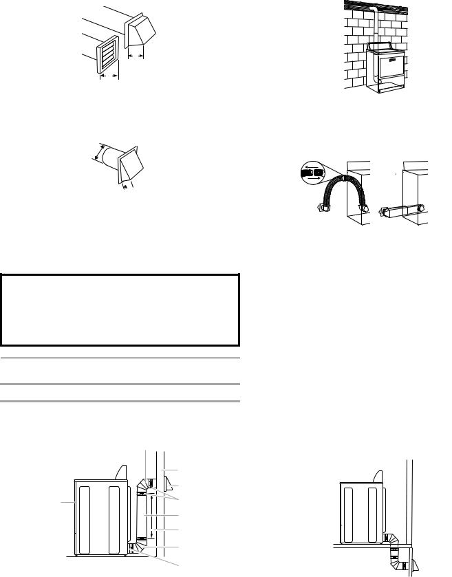
Exhaust
Recommended hood styles are shown here.
B
A
4" (102 mm)
4" (102 mm)
A.Louvered hood style
B.Box hood style
The angled hood style (shown here) is acceptable.
4" (102 mm)
 2½" (64 mm)
■An exhaust hood should cap the vent to keep rodents and insects from entering the home.
■Exhaust hood must be at least 12" (305 mm) from the ground or any object that may be in the path of the exhaust (such as flowers, rocks, or bushes, snow line, etc.).
■Do not use an exhaust hood with a magnetic latch.
Improper venting can cause moisture and lint to collect indoors, which may result in:
 Moisture damage to woodwork, furniture, paint, wallpaper, carpets, etc.
 Housecleaning problems and health problems.
PlanVentSystem
Choose your exhaust installation type
Recommended exhaust installations
Typical installations vent the dryer from the rear of the dryer. Other installations are possible.
|
B |
|
C |
|
D |
A |
E |
|
F |
|
G |
|
B |
|
H |
A. Dryer |
E. Clamps |
B. Elbow |
F. Rigid metal or flexible metal vent |
C. Wall |
G. Vent length necessary to connect elbows |
D. Exhaust hood |
H. Exhaust outlet |
Standard exhaust installation with rigid metal or flexible metal vent
Alternate installations for close clearances
Venting systems come in many varieties. Select the type best for your installation. Two close-clearance installations are shown. Refer to the manufacturer’s instructions.
AB
A.Over-the-top installation (also available with one offset elbow)
B.Periscope installation
NOTE: The following kits for close clearance alternate installations are available for purchase. Please see the “Assistance or Service” section of the Dryer User Instructions.
■Over-the-Top Installation: Part Number 4396028
■Periscope Installation (For use with dryer vent to wall vent mismatch):
Part Number 4396037 - 0" (0 mm) to 18" (457 mm) mismatch
Part Number 4396011 - 18" (457 mm) to 29" (737 mm) mismatch
Part Number 4396014 - 29" (737 mm) to 50" (1270 mm) mismatch
Special provisions for mobile home installations
The exhaust vent must be securely fastened to a noncombustible portion of the mobile home structure and must not terminate beneath the mobile home. Terminate the exhaust vent outside.
8
Loading...