


FOR CAR USE ONLY/POUR APPLICATION AUTOMOBILE/PARA USO EN AUTOMÓVILES
EN
X-A90M FR
MONO POWER AMPLIFIER
X-A70F ES
4 CHANNEL POWER AMPLIFIER
X-A90V
4 CHANNEL + MONO POWER AMPLIFIER
• |
OWNER’S MANUAL |
• MANUAL DE OPERACIÓN |
|
Please read before using this equipment. |
Léalo antes de utilizar este equipo. |
• |
MODE D’EMPLOI |
|
|
Veuillez lire avant d’utiliser cet appareil. |
|
|
|
|
|
ALPINE ELECTRONICS MARKETING, INC. |
ALPINE ELECTRONICS OF U.K. LTD. |
|
1-7, Yukigaya-Otsukamachi, Ota-ku, |
Alpine House |
|
Tokyo 145-0067, JAPAN |
Fletchamstead Highway, Coventry CV4 9TW, U.K. |
|
Phone: 03-5499-4531 |
www.alpine.co.uk |
|
ALPINE ELECTRONICS OF AMERICA, INC. |
ALPINE ELECTRONICS France S.A.R.L. |
|
19145 Gramercy Place, Torrance, |
184 allée des Erables |
|
California 90501, U.S.A. |
CS 52016 – Villepinte |
|
Phone 1-800-ALPINE-1 (1-800-257-4631) |
95 945 Roissy CDG cedex |
|
|
FRANCE |
|
ALPINE ELECTRONICS OF AUSTRALIA PTY. LTD. |
Phone : + 33(0)1 48 63 89 89 |
|
161-165 Princes Highway, Hallam |
ALPINE ITALIA S.p.A. |
|
Victoria 3803, Australia |
|
|
Phone 03-8787-1200 |
Viale Cristoforo Colombo, 8 |
|
|
20090 Trezzano sul Naviglio MI, Italy |
|
ALPINE ELECTRONICS GmbH |
Phone +39 02 484781 |
|
Wilhelm-Wagenfeld-Str. 1-3, |
ALPINE ELECTRONICS DE ESPAÑA, S.A. |
|
80807 München, Germany |
|
|
Phone 089-32 42 640 |
Portal de Gamarra 36, Pabellón, 32 |
|
|
01013 Vitoria (Alava)-APDO 133, Spain |
|
|
Phone 945-283588 |
|
Designed by ALPINE Japan |
|
Printed in Korea |
JEIL Moon Hwa Co. |
68-33122Z89-A (Y-A5) |
18-6, 3Ga, Pil_dong, Jung_gu, Seoul, Korea |
M3514640010 |
CONTENTS |
|
WARNING................................................................................ |
1 |
SERVICE CARE ....................................................................... |
2 |
ACCESSORIES ........................................................................ |
2 |
INSTALLATION....................................................................... |
3 |
REMOVING THE TOP COVER............................................. |
3 |
ATTACHING THE TERMINAL COVERS AND |
|
LOGO PLATE....................................................................... |
4 |
CONNECTIONS ..................................................................... |
5 |
CONNECTION CHECK LIST................................................ |
8 |
SWITCH SETTINGS............................................................... |
9 |
SYSTEM DIAGRAMS ......................................................... |
12 |
SPECIFICATIONS................................................................ |
20 |
WARNING |
|
Points to Observe for Safe Usage
Read this manual carefully before using the system components. They contain instructions on how to use this product in a safe and effective manner.
Alpine cannot be responsible for problems resulting from failure to observe the instructions in this manual.
This symbol means important instructions.
 WARNING Failure to heed them can result in serious injury or death.
DO NOT OPERATE ANY FUNCTION THAT TAKES YOUR ATTENTION AWAY FROM SAFELY DRIVING YOUR VEHICLE.
Any function that requires your prolonged attention should only be performed after coming to a complete stop. Always stop the vehicle in a safe location before performing these functions. Failure to do so may result in an accident.
KEEP THE VOLUME AT A LEVEL WHERE YOU CAN STILL HEAR OUTSIDE NOISES WHILE DRIVING.
Excessive volume levels that obscure sounds such as emergency vehicle sirens or road warning signals (train crossings, etc.) can be dangerous and may result in an accident. LISTENING AT LOUD VOLUME LEVELS IN A CAR MAY ALSO CAUSE HEARING DAMAGE.
English
DO NOT DISASSEMBLE OR ALTER.
Doing so may result in an accident, fire or electric shock.
USE THIS PRODUCT FOR MOBILE 12V APPLICATIONS.
Use for other than its designed application may result in fire, electric shock or other injury.
USE THE CORRECT AMPERE RATING WHEN REPLACING FUSES.
Failure to do so may result in fire or electric shock.
DO NOT BLOCK VENTS OR RADIATOR PANELS.
Doing so may cause heat to build up inside and may result in fire.
MAKE THE CORRECT CONNECTIONS.
Failure to make the proper connections may result in fire or product damage.
USE ONLY IN CARS WITH A 12 VOLT NEGATIVE GROUND.
(Check with your dealer if you are not sure.) Failure to do so may result in fire, etc.
BEFORE WIRING, DISCONNECT THE CABLE FROM THE NEGATIVE BATTERY TERMINAL.
Failure to do so may result in electric shock or injury due to electrical shorts.
DO NOT ALLOW CABLES TO BECOME ENTANGLED IN SURROUNDING OBJECTS.
Arrange wiring and cables in compliance with the manual to prevent obstructions when driving. Cables or wiring that obstruct or hang up on places such as the steering wheel, gear lever, brake pedals, etc. can be extremely hazardous.
DO NOT SPLICE INTO ELECTRICAL CABLES.
Never cut away cable insulation to supply power to other equipment. Doing so will exceed the current carrying capacity of the wire and result in fire or electric shock.
DO NOT DAMAGE PIPE OR WIRING WHEN DRILLING HOLES.
When drilling holes in the chassis for installation, take precautions so as not to contact, damage or obstruct pipes, fuel lines, tanks or electrical wiring. Failure to take such precautions may result in fire.
1-EN
DO NOT USE BOLTS OR NUTS IN THE BRAKE OR STEERING SYSTEMS TO MAKE GROUND CONNECTIONS.
Bolts or nuts used for the brake or steering systems (or any other safety-related system), or tanks should NEVER be used for installations or ground connections. Using such parts could disable control of the vehicle and cause fire etc.
KEEP SMALL OBJECTS SUCH AS BATTERIES OUT OF THE REACH OF CHILDREN.
Swallowing them may result in serious injury. If swallowed, consult a physician immediately.
This symbol means important instructions.
 CAUTION Failure to heed them can result in injury or property damages.
HALT USE IMMEDIATELY IF A PROBLEM APPEARS.
Failure to do so may cause personal injury or damage to the product. Return it to your authorized Alpine dealer or the nearest Alpine Service Center for repairing.
HAVE THE WIRING AND INSTALLATION DONE BY EXPERTS.
The wiring and installation of this unit requires special technical skill and experience. To ensure safety, always contact the dealer where you purchased this product to have the work done.
USE SPECIFIED ACCESSORY PARTS AND INSTALL THEM SECURELY.
Be sure to use only the specified accessory parts. Use of other than designated parts may damage this unit internally or may not securely install the unit in place. This may cause parts to become loose resulting in hazards or product failure.
ARRANGE THE WIRING SO IT IS NOT CRIMPED OR PINCHED BY A SHARP METAL EDGE.
Route the cables and wiring away from moving parts (like the seat rails) or sharp or pointed edges. This will prevent crimping and damage to the wiring. If wiring passes through a hole in metal, use a rubber grommet to prevent the wire’s insulation from being cut by the metal edge of the hole.
DO NOT INSTALL IN LOCATIONS WITH HIGH MOISTURE OR DUST.
Avoid installing the unit in locations with high incidence of moisture or dust. Moisture or dust that penetrates into this unit may result in product failure.
SERVICE CARE
IMPORTANT NOTICE
This Amplifier has been type tested and found to comply with the limits for a Class B computing device in accordance with the specifications in Subpart J of Part 15 of FCC Rules. This equipment generates and uses radio frequency energy, and it must be installed and used properly in accordance with the manufacturer’s instructions.
SERIAL NUMBER:
INSTALLATION DATE:
INSTALLATION TECHNICIAN:
PLACE OF PURCHASE:
 IMPORTANT
Please record the serial number of your unit in the space provided here and keep it as a permanent record. The serial number plate is located on the rear of the unit.
 For European Customers
Should you have any questions about warranty, please consult your store of purchase.
 For Customers in other Countries
IMPORTANT NOTICE
Customers who purchase the product with which this notice is packaged, and who make this purchase in countries other than the United States of America and Canada, please contact your dealer for information regarding warranty coverage.
ACCESSORIES |
|
• Self-Tapping Screw (M4 × 20)...................................... |
4 |
• Terminal Cover (F)/(L)/(R) ...................................... |
1 SET |
• Battery Connector ........................................................... |
1 |
• Speaker Connector |
|
X-A90M............................................................................. |
1 |
X-A70F .............................................................................. |
2 |
X-A90V.............................................................................. |
3 |
• Hexagon Wrench (Large)/(Small) ....................... |
1 SET |
• Logo Plate........................................................................... |
1 |
2-EN
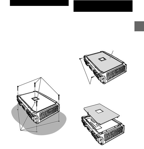
INSTALLATION
Due to the high power output of the X-A90M/ X-A70F/X-A90V considerable heat is produced when the amplifier is in operation. For this reason, the amplifier should be mounted in a location which will allow for free circulation of air, such as inside the trunk. For alternate installation locations, please contact your authorized Alpine dealer.
Mount the amplifier before installing the Terminal Cover (F)/(L)/(R).
1.Using the amplifier as a template, mark the four screw locations.
2.Make sure there are no objects behind the surface that may become damaged during drilling.
3.Drill the screw holes.
4.Position the X-A90M/X-A70F/X-A90V over the screw holes, and secure with four self-tapping screws.
Self-Tapping Screws
M4 × 20 (Included)
Holes
(e.g. X-A90V)
REMOVING THE TOP
COVER
When performing the Switch Setting, you must remove the Top Cover.
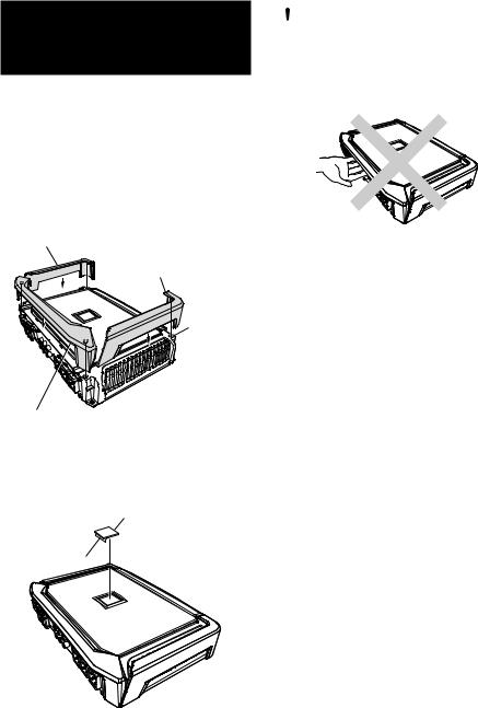
•Remove the Top Cover before installing or after removing the Terminal Cover (F). For details on how to remove the Terminal Cover (F), see ”ATTACHING THE TERMINAL COVERS AND LOGO PLATE” (page 4).
1.Remove the hexagon screws using the supplied Hexagon Wrench (Small).
Top Cover
Hexagon Screws
(e.g. X-A90V)
2.Slide the Top Cover, and lift it to remove.
• Be sure not to damage the indicator area.
(e.g. X-A90V)
3-EN
ATTACHING THE TERMINAL COVERS AND LOGO PLATE
Attach the terminal covers (included) after connections and confirmation of correct operation. Attaching the terminal covers will improve the appearance of the unit.
How to attach the terminal covers:
1.Attach the Terminal Cover (L)/(R) based on the guide hole of the amplifier.
2.Attach the Terminal Cover (F) based on the guide hole of the amplifier.
• Push in until the hook is securely engaged.
Terminal Cover (L)
Terminal Cover (R)
Guide Hole
Terminal Cover (F)
(e.g. X-A90V)
3.Peel the backing paper from the Logo Plate, then attach it to this unit in your desired direction.
Logo plate
 CAUTION
Do not lift or carry the unit by the attached terminal covers.
The terminal cover may detach causing the unit to fall resulting in personal injury or damage to the unit or the vehicle.
Backing Paper
(e.g. X-A90V)
4-EN

CONNECTIONS
Before making connections, be sure to turn the power off to all audio components.
*1 |
External Fuse*2 |
|
|
|
*3, 4 |
Vehicle’s battery
|
Vehicle’s chassis |
*1 |
For details on the wires size to be used, refer to the supplied “Cautions on Power Supply Wires Connection” and |
|
“Cautions on Power Supply Wires” (page 19), and then use the wire of the specified size. |
*2 |
Be sure to add an External Fuse (e.g. Fuse Block, Circuit Breaker) with the battery lead as close as possible to the |
|
battery’s positive (+) terminal. Add an external fuse with the same capacity, or a slightly larger capacity, as the sum total |
|
of the fuse capacities of the amplifier. |
|
For details on the fuse capacity of this machine, see “Battery Lead ( )” (page 6). |
*3 |
Connect all equipment to the same ground point while keeping wire length as short as possible. |
*4 |
To securely connect the ground lead, use an already installed screw. |
To prevent external noise from entering the audio system
•Locate the unit and route the leads at least 10 cm (4”) away from the vehicle’s harness.
•Keep the battery power leads as far away from other leads as possible.
•Connect the ground lead securely to a bare metal spot (remove any paint or grease if necessary) of the vehicle’s chassis.
•If you add an optional noise suppressor, connect it as far away from the unit as possible. Your Alpine dealer carries various noise suppressors, contact them for further information.
•Your Alpine dealer knows best about noise prevention measures so consult your dealer for further information.
5-EN
Power Supply Terminal |
|
Fuse |
|
X-A90M/X-A90V ................................................ |
30 A x 3 |
X-A70F .................................................................. |
35 A x 2 |
USE THE CORRECT AMPERE RATING WHEN REPLACING FUSES.
Failure to do so may result in fire or electric shock.
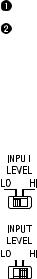
 Speaker Input Level Switch
Switch according to the Speaker input mode.
a) When making a speaker input connection with RCA Extension Cables (sold separately), set to “LO”.
b) When making a speaker input connection with Speaker-RCA Conversion Cables (sold separately), set to “HI”.
 RCA Input Jacks
Connect these jacks to the line out leads on your head unit using RCA extension cables or Speaker-RCA Conversion cable (sold separately). Be sure to observe correct channel connections; Left to Left and Right to Right.
 Pre-Out Jacks (X-A90M only)
These jacks provide a line level output. This is an ideal output for driving a second subwoofer amp. This output is full-range, and is not affected by the crossover.
 Remote Bass Control (Optional)
Connect the Remote Bass Control Unit RUX-KNOB or RUX-KNOB.2 (sold separately) to adjust the output level remotely. This is not to replace appropriate gain level setting between the amplifier and head unit.
• X-A70F supports RUX-KNOB.2 only.
 Speaker Output Terminals
 Battery Connector
Make the Battery, Remote Turn-on and Ground lead connections (as shown) to the Battery Connector.
Insert Plug to Terminal  .
.
•For details on how to connect, see “Cautions on wire lead connections” (page 7).
 Battery Lead (Sold Separately)
Be sure to add an External Fuse (e.g. Fuse Block, Circuit Breaker) with the battery lead as close as possible to the battery’s positive (+) terminal.
This fuse will protect your vehicle’s electrical system in case of a short circuit. See below for appropriate fuse value requirement:
X-A90M/X-A90V ....................................... |
90 amp fuse |
X-A70F ......................................................... |
70 amp fuse |
•For details on the wires size to be used, refer to the supplied “Cautions on Power Supply Wires Connection” and “Cautions on Power Supply Wires” (page 19), and then use the wire of
the specified size.
 Remote Turn-On Lead (Sold Separately)
Connect this lead to the remote turn-on (positive trigger, (+) 12 V only) lead of your head unit. If a remote turn-on lead is not available, see “CONNECTION CHECK LIST” section on
page 8 for alternative method.
•When connecting the speaker output leads of the head unit to this unit with a Speaker-RCA Conversion cable (sold separately), you do not need to connect the remote turn-on lead, owing to the “REMOTE SENSING” function of this unit. However, the “REMOTE SENSING” function may not work depending on the signal source connected. In such a case, connect the remote turn-on lead to an incoming power supply cord (accessory power) in the ACC position.
 Ground Lead (Sold Separately)
Connect this lead securely to a clean, bare metal spot on the vehicle’s chassis. Verify this point to be a true ground by checking for continuity between that point and the negative (–) terminal of the vehicle’s battery. Ground all your audio components to the same point on the chassis to prevent ground loops while keeping wire length as short as possible.
•For details on the wires size to be used, refer to the supplied “Cautions on Power Supply Wires Connection” and “Cautions on Power Supply Wires” (page 19), and then use the wire of
the specified size.
 Speaker Connector
Make the Speaker Output Lead (+)/(-) connections to the Speaker Connector. Insert Plug to Terminal  .
.
•For details on how to connect, see “Cautions on wire lead connections” (page 7).
Be sure to observe correct speaker output connections and polarity in relation to the other speakers in the system. Connect the positive output to the positive speaker terminal and the negative to negative.
6-EN
 Loading...