


PXA-H701

FOR CAR USE ONLY/NUR FÜR AUTOMOBIL GEBRAUCH/POUR APPLICATION AUTOMOBILE UNIQUEMENT/
PARA USO EN AUTOMÓVILES/SOLO PER L'UTILIZZO IN AUTOMOBILE/ENDAST FÖR BILBRUK
R
PXA-H701
EN
MULTIMEDIA MANAGER™
• OWNER'S MANUAL
Please read before using this equipment.
• BEDIENUNGSANLEITUNG
Lesen Sie diese Bedienungsanleitung bitte vor
Gebrauch des Gerätes.
• MODE D'EMPLOI
Veuillez lire avant d’utiliser cet appareil.
• MANUAL DE OPERACIÓN
Léalo antes de utilizar este equipo.
• ISTRUZIONI PER L’USO
Si prega di leggere prima di utilizzare il
attrezzatura.
• ANVÄNDARHANDLEDNING
Innan du använder utrustningen bör du läsa
igenom denna användarhandledning.
®
DE
FR
ES
ES
IT
IT
ALPINE ELECTRONICS MARKETING, INC.
1-1-8 Nishi Gotanda,
Shinagawa-ku, Tokyo 141-0031, Japan
Phone 03-5496-8231
ALPINE ELECTRONICS OF AMERICA, INC.
19145 Gramercy Place, Torrance,
California 90501, U.S.A.
Phone 1-800-ALPINE-1 (1-800-257-4631)
ALPINE ELECTRONICS OF CANADA, INC.
7300 Warden Ave., Suite 203, Markham,
Ontario L3R 9Z6, Canada
Phone 1-800-ALPINE-1 (1-800-257-4631)
Kukje Printing Co., Ltd
127-2 Gamjeon-dong
Sasang-gu
Busan Korea
ALPINE ELECTRONICS OF AUSTRALIA PTY. LTD.
6-8 Fiveways Boulevarde Keysborough,
Victoria 3173, Australia
Phone 03-9769-0000
ALPINE ELECTRONICS GmbH
Frankfurter Ring 117, 80807 München,
ALPINE ELECTRONICS OF U.K. LTD.
Germany
Phone 089-32 42 640
Alpine House
Fletchamstead Highway,
Coventry CV4 9TW, U.K.
Phone 0870-33 33 763
ALPINE ELECTRONICS FRANCE S.A.R.L.
(RCS PONTOISE B 338 101 280)
98, Rue de la Belle Etoile, Z.I. Paris
Nord II, B.P. 50016, 95945 Roissy
Charles de Gaulle Cedex, France
Phone 01-48638989
ALPINE ITALIA S.p.A.
Viale C. Colombo 8, 20090 Trezzano
Sul Naviglio (MI), Italy
Phone 02-484781
ALPINE ELECTRONICS DE ESPAÑA, S.A.
Portal de Gamarra 36, Pabellón, 32
01013 Vitoria (Alava) - APDO 133, Spain
Phone 945-283588
Designed by ALPINE Japan
Printed in Korea (S)
68-00493Z09-A
SE
SE

ENGLISH
Before using
The control unit for the PXA-H701 is sold separately. The operation method
using this control unit (sold separately) is printed in this instruction manual.
However, if you use head units such as the IVA-D300 series or the IVA-D900
series, you can also operate the PXA-H701 from these head units (Items
such as AUTO TCR and navigation system voice guidance interruption
settings can only be operated from the Control Unit). For more details on the
head unit operation, see “External Audio Processor (Optional)” in the
instruction manual for the head unit.
FR
Contents
Operating Instructions
WARNING
WARNING.................................................. 2
CAUTION ................................................... 2
PRECAUTIONS ......................................... 3
Basic Operation
Turning the power on and off .......................................... 4
About indicators .............................................................. 4
Operating the Rotary encoder .......................................... 4
Setting the speakers ......................................................... 4
Using with Ai-NET connections ..................................... 5
Using with RCA-type or optical cable connections
(non Ai-NET connections) (only when using the
control unit sold separately) ...................................... 5
Automatic Adjustments
Performing time correction automatically
(Automated Time Correction) ................................... 6
Settings/Adjustments
Performing time correction manually (TCR)/Switching
the phase .................................................................... 8
Bass Focus ..................................................................... 10
Graphic equalizer adjustments ...................................... 12
Parametric equalizer adjustments .................................. 13
X-OVER ........................................................................ 15
X-OVER adjustment...................................................... 16
MX settings ................................................................... 18
BASS COMP. setting ..................................................... 19
Using Dolby Surround
Using the Pro Logic II mode ......................................... 20
Adjustment procedure for Dolby Surround ................... 21
Speaker setup ................................................................. 22
Adjusting the speaker levels .......................................... 22
Mixing bass sound to the rear channel .......................... 23
Adjusting the acoustic image ......................................... 24
Achieving powerful high volume sound........................ 25
Adjusting the DVD level ............................................... 25
Convenient Functions
Navigation system voice guidance interruption (only
when using the control unit sold separately) ........... 26
Linear PCM setting ....................................................... 26
Display settings ............................................................. 27
MX mode setting (Ai-NET connection) ........................ 27
Storing settings in the memory ...................................... 28
Calling out stored values ............................................... 28
Defeat mode ................................................................... 28
Switching the display mode .......................................... 29
Installation and Connections
Warning ......................................................................... 30
Caution .......................................................................... 30
Precautions .................................................................... 31
Accessories .................................................................... 32
Installation ..................................................................... 33
Basic Connections Diagram .......................................... 36
Examples of system expansion ...................................... 37
Information
Terminology .................................................................. 41
Others
In case of difficulty ........................................................ 42
Specifications ................................................................ 43
ES
DE
IT
SE
1-EN

WARNING
WARNING
This symbol means important instructions.
Failure to heed them can result in serious injury
or death.
DO NOT OPERATE ANY FUNCTION THAT TAKES
YOUR ATTENTION AWAY FROM SAFELY DRIVING
YOUR VEHICLE.
Any function that requires your prolonged attention
should only be performed after coming to a complete stop.
Always stop the vehicle in a safe location before
performing these functions. Failure to do so may result in
an accident.
KEEP THE VOLUME AT A LEVEL WHERE YOU CAN
STILL HEAR OUTSIDE NOISE WHILE DRIVING.
Failure to do so may result in an accident.
MINIMIZE DISPLAY VIEWING WHILE DRIVING.
Viewing the display may distract the driver from looking
ahead of the vehicle and cause an accident.
DO NOT DISASSEMBLE OR ALTER.
Doing so may result in an accident, fire or electric shock.
CAUTION
This symbol means important instructions.
Failure to heed them can result in injury or
material property damage.
HALT USE IMMEDIATELY IF A PROBLEM APPEARS.
Failure to do so may cause personal injury or damage to
the product. Return it to your authorized Alpine dealer or
the nearest Alpine Service Center for repairing.
USE THIS PRODUCT FOR MOBILE 12V
APPLICATIONS.
Use for other than its designed application may result in
fire, electric shock or other injury.
KEEP SMALL OBJECTS SUCH AS BATTERIES OUT
OF THE REACH OF CHILDREN.
Swallowing them may result in serious injury. If
swallowed, consult a physician immediately.
USE THE CORRECT AMPERE RATING WHEN
REPLACING FUSES.
Failure to do so may result in fire or electric shock.
USE ONLY IN CARS WITH A 12 VOLT NEGATIVE
GROUND.
(Check with your dealer if you are not sure.) Failure to do
so may result in fire, etc.
DO NOT BLOCK VENTS OR RADIATOR PANELS.
Doing so may cause heat to build up inside and may result
in fire.
2-EN

PRECAUTIONS
Temperature
Be sure the temperature inside the vehicle is between
+60°C (+140°F) and –10°C (+14°F) before turning your
unit on.
Installation Location
Make sure the PXA-H701 will not be installed in a
location subjected to:
• Direct sun and heat
• High humidity and water
• Excessive dust
• Excessive vibrations
Maintenance
If you have problems, do not attempt to repair the unit
yourself. Return it to your Alpine dealer or the nearest
Alpine Service Station for servicing.
FR
ES
3-EN
DE
IT
SE
Basic Operation
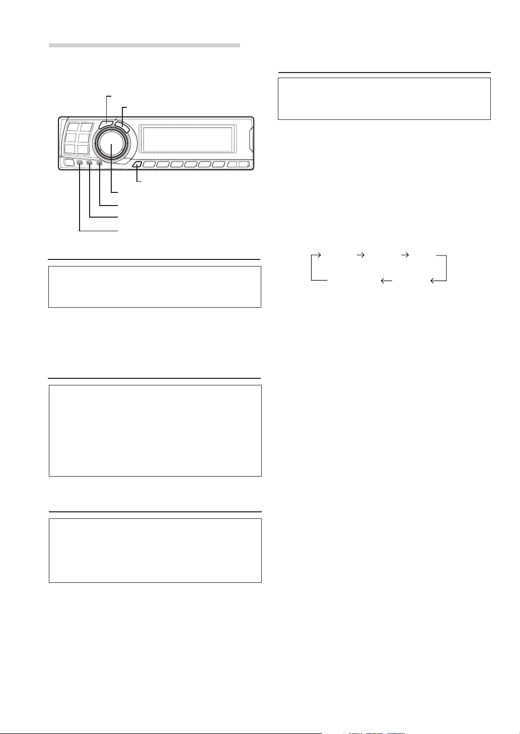
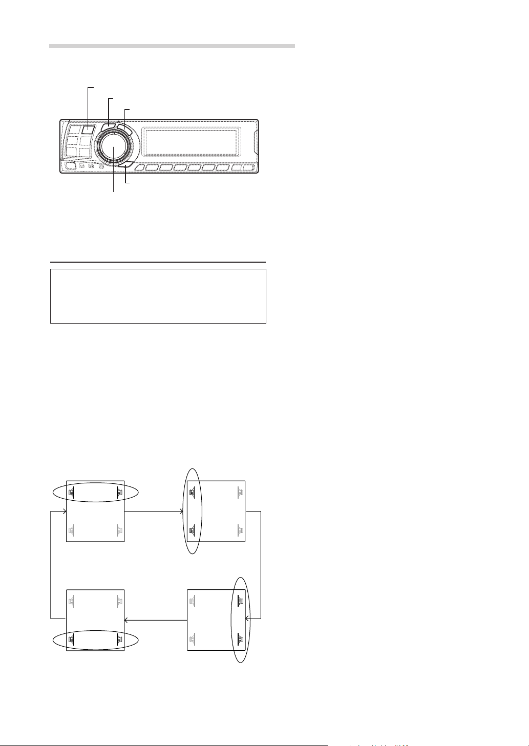
Setting the speakers
CHANNEL
ENTER
SETUP
Rotary encoder
PRO LOGIC II indicator
Dolby Digital indicator
DTS indicator
Turning the power on and off
This unit does not have a power switch. The head
unit to which the unit is connected, controls its
power.
NOTE
When the power is turned ON for the first time, the
SETUP mode is automatically activated.
About indicators
• PRO LOGIC II indicator
Lights amber in the Dolby Surround decode
mode
• Dolby Digital indicator
Lights amber in the Dolby Digital decode mode
• DTS indicator
Lights amber in the DTS decode mode
Operating the Rotary encoder
This unit uses the Rotary encoder when
establishing settings or adjustments. When
operating with the Rotary encoder, press the
Rotary encoder and startup the Rotary encoder
before the operation.
First make the speaker settings.
Turn off speaker channels that are not
connected.
1 Press the SETUP button.
The setup mode is set.
2 Turn the Rotary encoder to select the
“SPEAKER SELECT” mode, then press the
ENTER button.
3 Press the CHANNEL button to select the
speaker, then press the ENTER button.
F1
(Front 1)F2(Front 2)
Sub. W
(Subwoofer)
(Rear)
Ct
(Centre)
R
4 Turn the Rotary encoder to set the speaker type
ON or OFF, then press the ENTER button.
Repeat steps 3 and 4 to set all unconnected
speaker channels to “OFF”.
F1 (Front 1): Tw (Tweeter)/Full (Full Range)/OFF
F2 (Front 2): Full (Full Range)/OFF
R (Rear) : ON/OFF
Ct (Centre) : Centre/Sub.W (Subwoofer)/OFF
NOTE
Set to “Subwoofer” when a subwoofer is connected to
the centre speaker output.
Sub.W (Subwoofer) : ON/OFF
* When Full (Full Range) is selected in F1
(Front 1), the confirmation message of
Tweeter presence will be displayed next.
Turn the Rotary encoder and select YES/
NO, then press the ENTER button. Please
set to protect the speakers.
5 Press the SETUP button repeatedly to quit the
setup mode.
4-EN

Using with Ai-NET connections
When Ai-NET connections are used, the volume,
subwoofer, balance and fader are adjusted from
the head unit (they cannot be adjusted from the
PXA-H701). However, BASS and TREB can not
be adjusted from the head unit, so adjust them
from PXA-H701.
Using with RCA-type or optical cable
connections (non Ai-NET connections)
(only when using the control unit sold
separately)
Switching the input
The PXA-H701 is equipped with three sets of
analog signal inputs and three sets of digital
signal inputs. For further information about
connections, see Page 36.
1 Press the SETUP button.
The setup mode is set.
2 Turn the Rotary encoder to select the “INPUT
SELECT” mode, then press the ENTER button.
3 Turn the Rotary encoder to select the input
mode, then press the ENTER button.
Analog 1 Analog 2 Analog 3
Digital 3 Digital 2 Digital 1
Adjusting the input level
Using the analog, RCA-type connections, the
PXA-H701’s input level must be preset from the
head unit.
Adjust the input level using a sound source with
a high recording level (such as pop or rock
music).
1 Turn on the head unit’s power.
2 Turn the Rotary encoder on the main unit
counterclockwise and set the volume level to “0”.
3 Gradually increase the volume of the head unit
until “INPUT LEVEL OVER” appears in the
display.
Reduce the volume slightly from this position,
until “INPUT LEVEL OVER” display just turns off.
This completes the setting.
Do not change the head unit volume level from
this optimum setting. Use the PXA-H701, only,
for changing the volume level.
NOTE
Switch to the spectrum analyzer display mode or the
input channel display mode before adjusting the input
level. (See page 29)
Adjusting the volume, balance, fader and subwoofer
After determining the input level, adjust the
volume, balance, fader and subwoofer from the
PXA-H701. Be careful not to make these
adjustments on the head unit.
1 Press the ENTER button and select the mode to
be adjusted.
EN
FR
ES
DE
4 Press the SETUP button repeatedly to quit the
setup mode.
NOTE
Non Ai-NET connections
Alpine products are equipped for a bus connection
system called “Ai-NET” which can only be used for
connections between Ai-NET products.
The PXA-H701 is an Ai-NET product, but is designed to
allow connections to other (non Ai-NET) products as
well. Thus RCA-type and optical cable connections are
also possible.
Connections to non Ai-NET products are referred to as
“non Ai-NET connections”.
VOLUME FADERBALANCE
Sub.W LEVEL
2 Turn the Rotary encoder within 5 seconds and
adjust to the desired level.
VOLUME : 0 ~ 35
BALANCE : L15 ~ R15
FADER : F15 ~ R15
Sub.W LEVEL : 0 ~ +15
NOTE
When the subwoofer is set to “OFF”, the Sub.W
LEVEL adjustment is ineffective.
5-EN
IT
SE
AUT TCR
O
10 sec .
to start
Automatic Adjustments
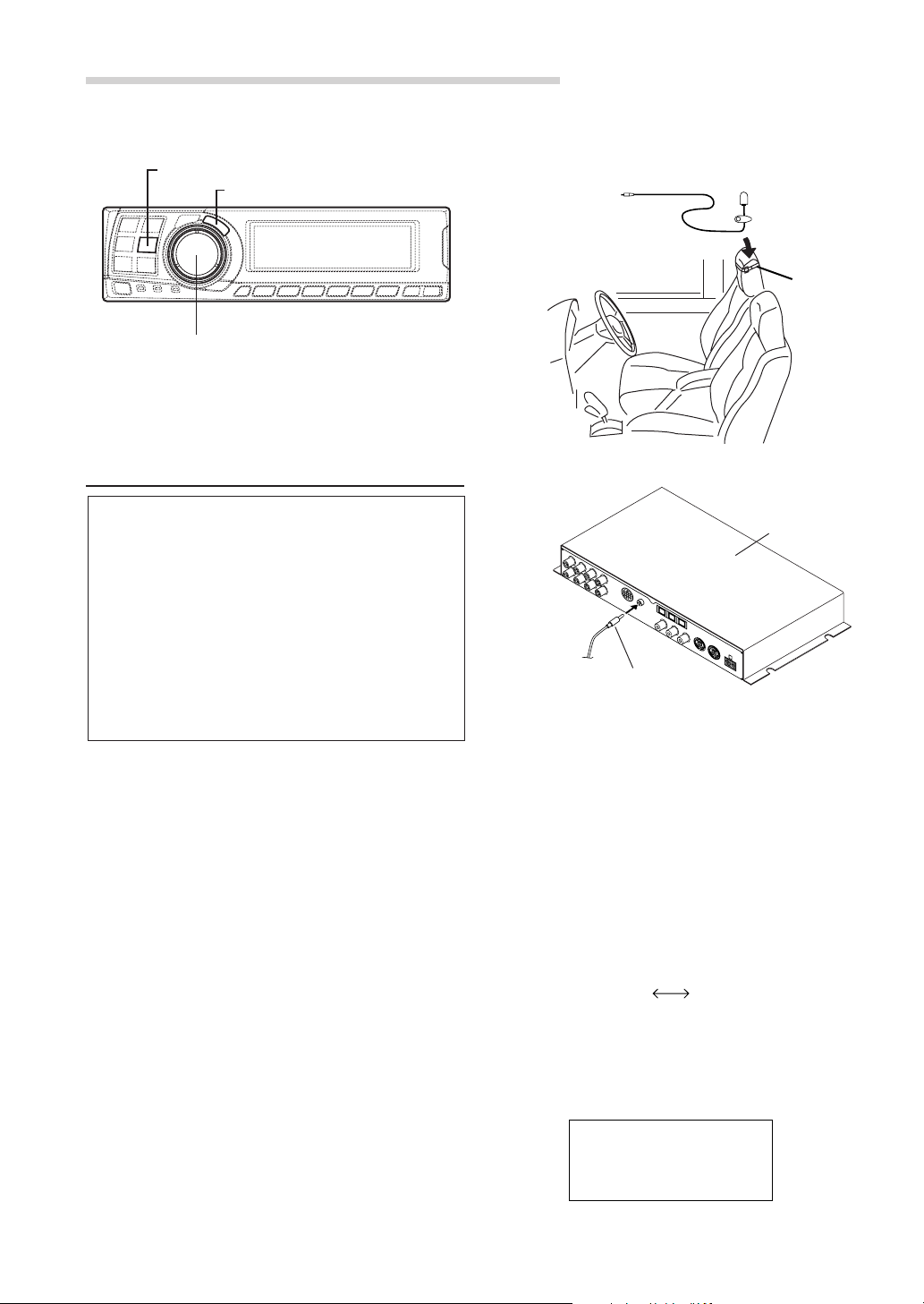
3 Connect the microphone.
1) Fasten the microphone included with control
unit at the centre of the driver’s seat’s
AUTO TCR
ENTER
Rotary encoder
Performing time correction automatically
(Automated Time Correction)
headrest facing upwards.
To microphone
input jack
2) Connect the microphone to the PXA-H701.
Microphone
Belt, etc.
Due to the particular conditions inside the
vehicle, there is a major difference between the
distances of the various speakers and the
listening position. This function uses the
included measurement microphone to
automatically measure and analyse the distances
between the speakers and the listening position
and perform the optimum time correction.
The AUTO TCR operation from the head unit
may not be performed depending on the head
unit combination.
1 Check that the defeat mode is off.
(See page 28.)
2 Prepare the vehicle.
1) Park the vehicle in a quiet place.
2) Close the vehicle’s doors and windows.
Base unit
To microphone
input jack
Microphone
4 Set the vehicle’s engine key to the ACC position.
• Vibrations could make it difficult to achieve
the appropriate adjustment values, so turn
the engine off.
• Noise could make it impossible for automatic
measurements to be made, so make sure
the air conditioner, heater and all other
devices are turned off.
5 Press the AUTO TCR button.
6 Turn the Rotary encoder, select the tweeter
setting, then press the ENTER button.
YES
NO
6-EN
The count down starts.
7 Once the count down starts, get out of the
vehicle and shut the doors within 10 seconds.

With the automatic adjustment function, the
operation described below is performed.
Adjustments are completed in about 10 seconds.
Time correction.
“END” is displayed for about 15 seconds and the
automatic adjustment is completed.
• If the microphone does not pick up the
sound or the speakers are not working or are
connected or wired improperly, the automatic
adjustments are not performed and a error
message is displayed.
Check the various speakers then perform the
automatic adjustments again.
AUT TCR
O
ERROR
8 Check that the automatic adjustment has been
completed (that “END” has been displayed for
about 15 seconds), then get back into the
vehicle and disconnect the microphone.
EN
FR
ES
9 To store, follow the procedure described at
“Storing settings in the memory” (page 28).
NOTES
• Automatic measurements cannot be made unless the
microphone is connected (error display). To perform
time correction automatically, be sure to connect the
included microphone first.
• Before making automatic measurements, press the
AUTO TCR button to cancel it.
• No other operations can be performed while
measurements are being made.
• Measurements will differ according to the position in
which the microphone is mounted.
• Note that using for extended periods of time without
turning on the engine may wear down the battery.
• Automatic measurements cannot be made for the
subwoofer. Make the subwoofer setting manually.
Refer to “Performing time correction manually
(TCR)/Switching the phase” (page 8).
• When the speaker is set to the “OFF” mode, the TCR
for that speaker cannot be adjusted. Refer to “Setting
the speakers” (page 4).
• After making the settings, we recommend storing
them in the memory. For instructions, see page 28.
DE
IT
SE
7-EN
Settings/Adjustments
• Concrete examples
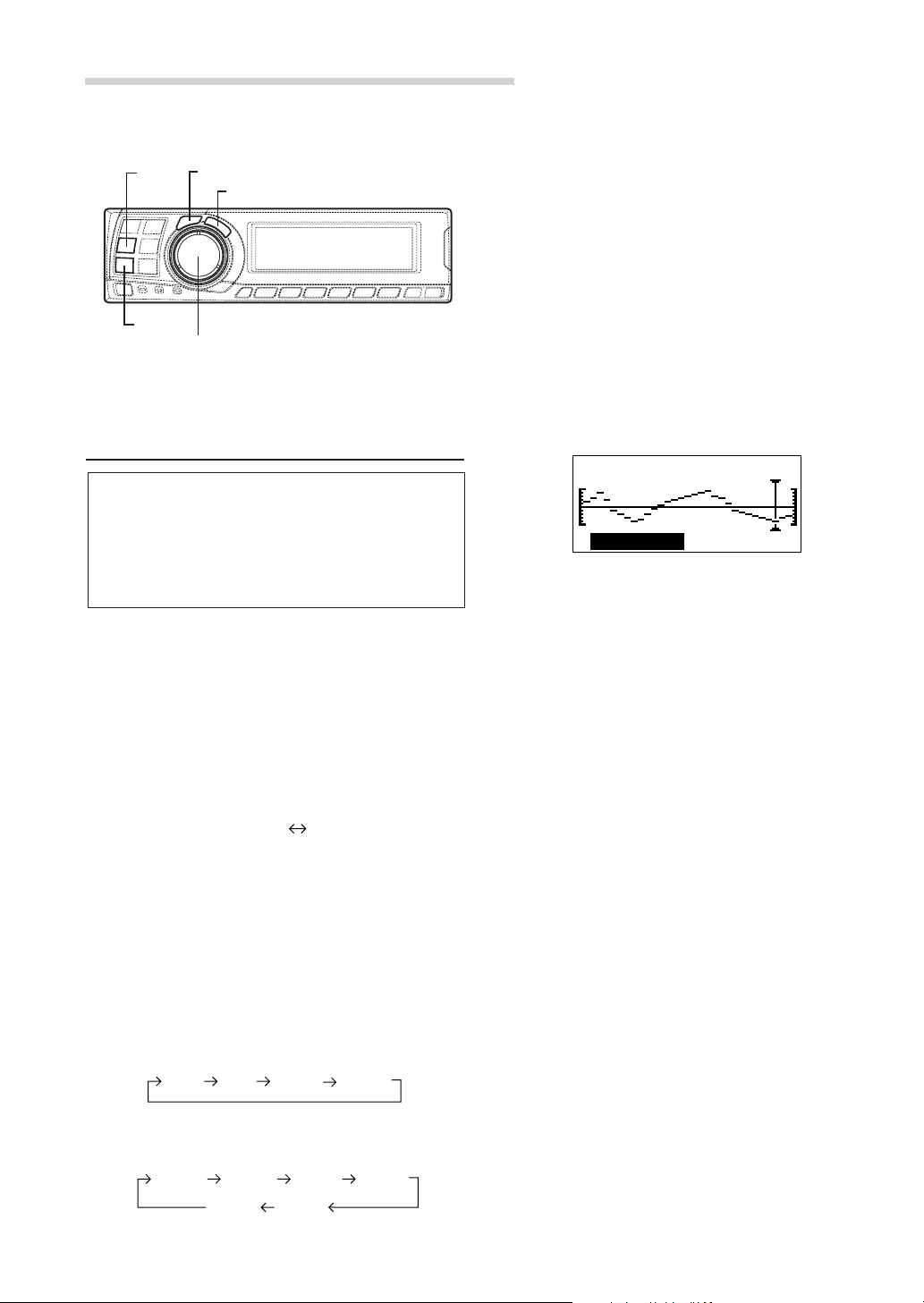
TCR/PHASE
CHANNEL
ENTER
Rotary encoder
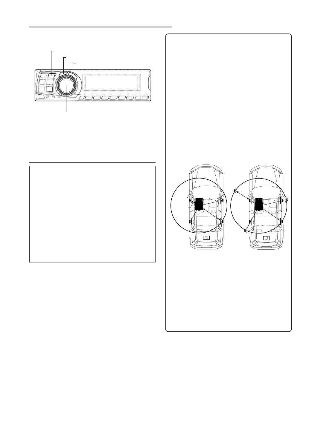
Performing time correction manually
(TCR)/Switching the phase
Because of the particular conditions inside the
vehicle, there are major differences in the
distances between the different speakers and the
listening position. The proper time correction can
be obtained using the automatic time correction
function (“AUTO TCR”), but it is also possible to
calculate the optimum correction values and
eliminate the time error at the listening position
yourself using this function. You can also use this
function to switch the phase.
When operating with head units such as the IVAD300 series, the adjustment is different
depending on the head unit.
1 Check that the defeat mode is off.
(See page 28.)
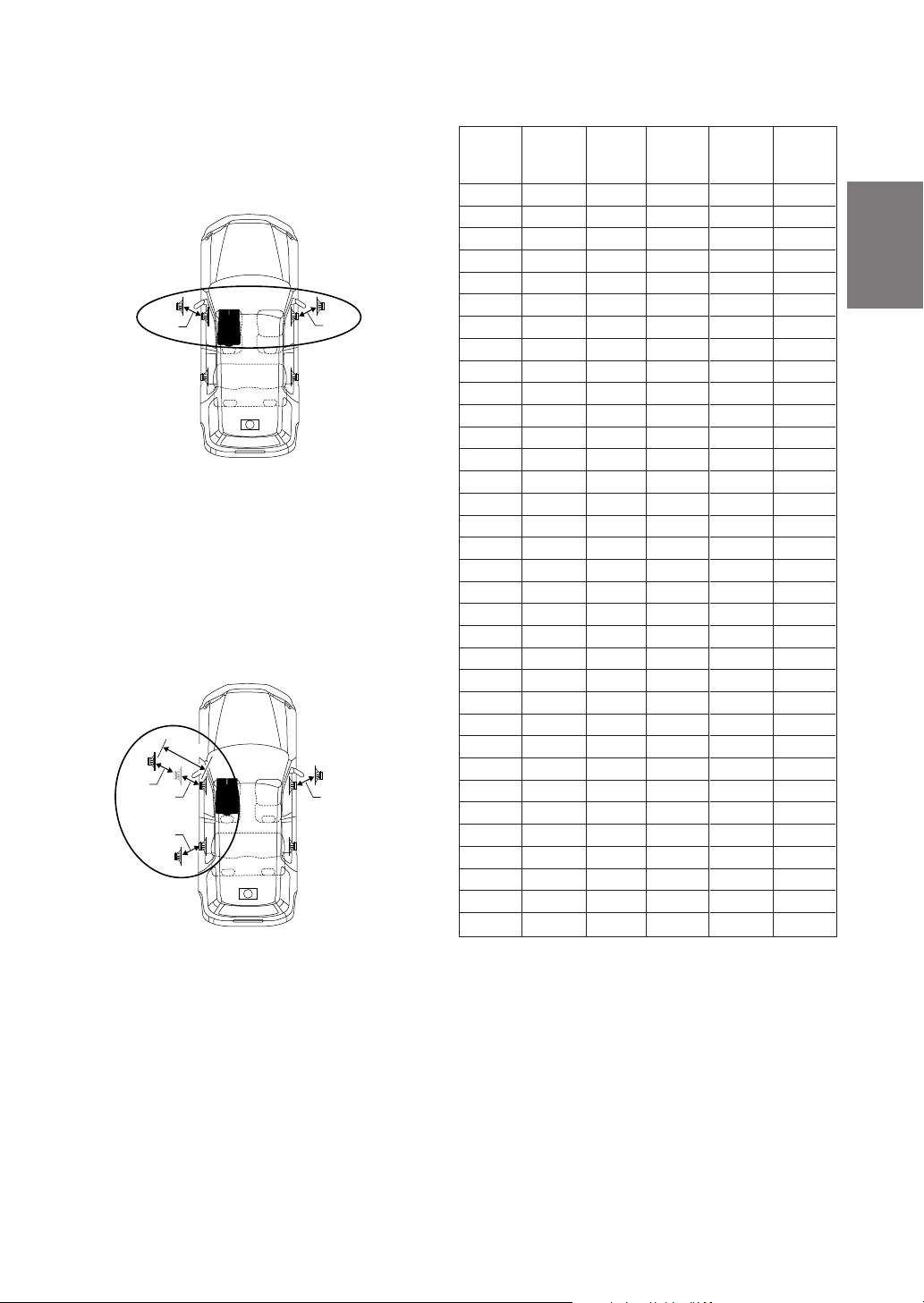
2 Sit in the listening position (the driver’s seat, for
example) and measure the distance (in meters)
between your head and the various speakers.
3 Calculate the difference in distance between the
farthest speaker and the other speakers.
L = (distance of farthest speaker)
– (distance of other speakers)
4 Divide the distances calculated for the different
speakers by the speed of sound (343 m/s
temperature 20°C).
This value is the time correction value for the
different speakers.
1.Calculating the time correction value for the
5 Press the TCR/PHASE button to set the time
front left speaker on the diagram below.
Conditions:
Distance between farthest speaker and
listening position: 2.25 m (88-3/4")
Distance between front left speaker and
listening position: 0.5 m (20")
Calculation: L = 2.25 m (88-3/4") – 0.5 m (20")
= 1.75 m (68-3/4")
Compensation time = 1.75 ÷ 343 x 1000
= 5.1 (ms)
In other words, setting the time correction value
for the front left speaker to 5.1 (ms) sets a
virtual distance matching the distance to the
farthest speaker.
5.1ms
0.5m
2.25m
The sound is uneven
because the distance
between the listening
position and the different
speakers is different.
The difference in the
distance between the
front left and rear right
speakers is 1.75 meters
(68-3/4").
correction mode.
Time correction eliminates
the difference between
the time required for the
sound from the different
speakers to reach the
listening position.
Setting the time correction
of the front left speaker to
5.1 ms makes it possible
to coordinate the distance
from the listening position
to the speaker.
8-EN
6 Press and hold the CHANNEL button for at least
2 seconds and select “L and R (LR)” or “L or R”.
L and R (LR) L or R
(factory default)
9 Turn the Rotary encoder to switch the phase,
then press the CHANNEL button.
Press the ENTER button to return to step 8.
0 180
L and R (LR):Sets the same adjustment values
for the left and right channels.
L or R: Different adjustment values can be
set for the left and right channels.
7 Press the CHANNEL button and select the
desired channel, then press the ENTER button.
When “L and R (LR)” is selected:
*1
Center
Front 1 Front 2
When “L or R” is selected:
Front 1 L Front 1 R
Sub. W
*1 When centre is set to subwoofer, it is not
displayed.
*2 When centre is set to subwoofer, it becomes
Sub.W(L).
*3 When centre is set to subwoofer, it becomes
Sub.W(R).
Center
Rear
Sub. W
Front 2 L
*2*3
Rear R Rear L
Front 2 R
8 Turn the Rotary encoder to adjust the time
correction value (0.00 ~ 20.00ms), then press
the ENTER button.
TCR HPASEFL 1RR/
:
DE YCLA
10. ms2
C
R
5
PHA : 180 °SE
10
Repeat steps 7 to 9 to adjust other channels.
11
Once the adjustments are completed, press the
TCR/PHASE button.
NOTES
• When the speaker is set to the “OFF” mode, the TCR
for that speaker is ineffective. Refer to “Setting the
speakers” (page 4).
• After making the settings, we recommend storing
them in the memory. For instructions, see page 28.
EN
FR
ES
DE
TCR HPASEFL 1RR/
:
DE YCLA
10. ms2
C
R
5
PHA : 18 0 °SE
* The difference in the sound when the defeat
mode is turned off (adjusted time
correction) and on (default value) can be
checked as follows:
1) While in the adjustment mode, press and
hold the TCR/PHASE button for at least 2
seconds.
2) Press the TCR/PHASE button to switch the
defeat mode on and off and listen to the
difference in the sound.
3) To quit, select the desired setting, then press
the ENTER button.
Note that if you press the ENTER button with
the defeat mode turned on, the adjustments
are reset to the defeat on status (the default
values).
IT
SE
9-EN
Settings/Adjustments
5 Turn the Rotary encoder to set the step of front-
rear/left-right.
TCR/PHASE
CHANNEL
ENTER
B.C.
Rotary encoder
6 Moreover, for setting another channel (speaker),
repeat steps 4 and 5.
7 After completing the setting, press the ENTER
button to return to the time correction mode.
Here, you can compare the sound of Defeat OFF
(adjustment value) and Defeat ON (initial).
For the operation method, refer to step 8 of
“Performing time correction manually (TCR)/
Switching the phase” on page 9.
8 Press the TCR/PHASE button to complete the
setting.
Bass Focus
The time difference between the front-rear/leftright speakers, can be adjusted a pair at a time.
Audible time correction can be made from 0.05
ms to 20.00 ms in 401 steps (0 to 400).
1 Check that the defeat mode is off.
(See page 28.)
2 Press the TCR/PHASE button to select the time
correction mode.
3 Press the B.C. button to select the “BASS
FOCUS” setting mode.
4 Press the CHANNEL button to select the front-
rear/left-right speaker.
FL FR
RL RR
FL FR
RL RR
NOTE
The setting made in Bass Focus is reflected in the time
correction.
Front (left-right)
speakers
FL FR
RL RR
Rear (left-right)
speakers
10-EN
Left (front-rear)
speakers
FL FR
RL RR
Right (front-rear)
speakers
Example of Steps 4 and 5 Setting
1.After entering corrections for the front (left and
right) speakers in STEP 30, the time difference
is 1.5 ms for both front-left and front-right
speakers.
1.5ms
1.5ms
2. After entering corrections for the left (front and
rear) speakers in STEP 30, the time difference
becomes 3.0 ms* for the front left speaker, and
1.5 ms for the left rear speaker.
* Because the time difference was already set
to 1.5 ms for the front left speakers in STEP 1,
the additional correction in STEP 30 makes
the time difference of the front left speaker 3.0
ms.
3.0ms
1.5ms
1.5ms
1.5ms
1.5ms
Time difference Table
Number
of
steps
10
11
12
13
14
15
16
17
18
19
20
21
22
23
24
25
26
27
28
29
30
31
32
33
0
1
2
3
4
5
6
7
8
9
Time
Difference
(ms)
0.00
0.05
0.10
0.15
0.20
0.25
0.30
0.35
0.40
0.45
0.50
0.55
0.60
0.65
0.70
0.75
0.80
0.85
0.90
0.95
1.00
1.05
1.10
1.15
1.20
1.25
1.30
1.35
1.40
1.45
1.50
1.55
1.60
1.65
Number
of
steps
34
35
36
37
38
39
40
41
42
43
44
45
46
47
48
49
50
51
52
53
54
55
56
57
58
59
60
61
62
63
64
65
66
67
Time
Difference
(ms)
1.70
1.75
1.80
1.85
1.90
1.95
2.00
2.05
2.10
2.15
2.20
2.25
2.30
2.35
2.40
2.45
2.50
2.55
2.60
2.65
2.70
2.75
2.80
2.85
2.90
2.95
3.00
3.05
3.10
3.15
3.20
3.25
3.30
3.35
Number
of
steps
68
69
70
71
72
73
74
75
76
77
78
79
80
81
82
83
84
85
86
87
88
89
90
91
92
93
94
95
96
97
98
99
100–399
400
Time
Difference
(ms)
3.40
3.45
3.50
3.55
3.60
3.65
3.70
3.75
3.80
3.85
3.90
3.95
4.00
4.05
4.10
4.15
4.20
4.25
4.30
4.35
4.40
4.45
4.50
4.55
4.60
4.65
4.70
4.75
4.80
4.85
4.90
4.95
5.00–19.95
20.00
EN
FR
ES
DE
IT
11-EN
SE
Settings/Adjustments
G.EQ
P.EQ
Graphic equalizer adjustments
The graphic equalizer allows you to modify the
sound using 31 bands each for the front (left and
right), rear (left and right) and centre speakers.
An additional 10 bands are available for the
subwoofer. This allows you to customize the
sound to suit your taste.
CHANNEL
ENTER
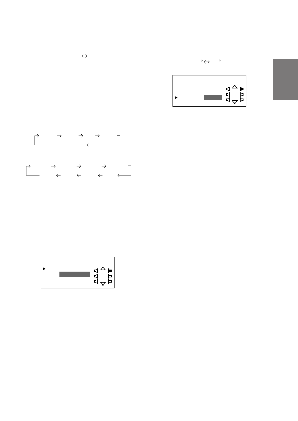
5 Turn the Rotary encoder to select the
Rotary encoder
6 Turn the Rotary encoder to adjust the level (± 9
7 Repeat steps 5 and 6 to adjust other
*1 When centre is set to subwoofer, it is not
displayed.
*2 When centre is set to subwoofer, it becomes
Sub.W(L).
*3 When centre is set to subwoofer, it becomes
Sub.W(R).
frequency, then press the ENTER button.
Adjustable frequencies
Front/Rear/Centre: 20Hz~20kHz (1/3 octave
step)
Sub.W: 20Hz~160Hz (1/3 octave step)
dB in steps of 1 dB), then press the ENTER
button.
31– .EQFront LG
12.5kHz
frequencies.
– 9dB
1 Check that the defeat mode is off.
(See page 28.)
2 Press the G.EQ button to set the graphic
equalizer mode.
3 Press and hold the CHANNEL button for at least
2 seconds and select “L and R (LR)” or “L or R”.
L and R (LR) L or R
(factory default)
L and R (LR):Sets the same adjustment values
for the left and right channels.
L or R: Different adjustment values can be
set for the left and right channels.
4 Press the CHANNEL button to select the desired
channel, then press the ENTER button.
When “L and R (LR)” is selected:
Front Rear Center
When “L or R” is selected:
Front L Front R
Sub. W
*1
Rear L
Center
Sub. W
Rear R
*2*3
12-EN
8 To adjust other channels, press the CHANNEL
button to return to step 4.
* The difference in the sound when the defeat
mode is turned off (adjusted graphic
equalizer settings) and on (default values)
can be checked as follows:
1) While in the adjustment mode, press and
hold the G.EQ button for at least 2 seconds.
2) Press the G.EQ button to switch the defeat
mode on and off and listen to the difference
in the sound.
3) To quit, select the desired setting, then press
the ENTER button.
Note that if you press the ENTER button with
the defeat mode turned on, the adjustments
are reset to the defeat on status (the default
values).
9 Once the adjustments are completed, press the
G.EQ button.
NOTES
• When the speaker is set to the “OFF” mode, the
graphic equalizer for that speaker is ineffective.
Refer to “Setting the speakers” (page 4).
• Check the playable frequency ranges of the connected
speakers before making the equalizer adjustments. If
the speaker’s playable frequency range is 55 Hz to 30
kHz, for example, adjusting the 40 Hz or 20 Hz band
has no effect. Additionally, you may overload and
damage the speakers.
• After making the settings, we recommend storing
them in the memory. For instructions, see page 28.
• When graphic EQ is adjusted, the adjustment for
parametric EQ becomes ineffective.

Parametric equalizer adjustments
The frequency bands of the graphic equalizer are
fixed. This makes it very difficult to correct for
undesired peaks and dips at specific frequencies.
The parametric equalizer’s centre frequency can
be tuned these specific frequencies. Then, the
bandwidth (Q) and level are fine-tuned,
independently, to make the necessary
corrections. The parametric equalizer function is
an advanced tool for serious audiophiles.
6 Turn the Rotary encoder to select the
frequency, then press the ENTER button.
For the adjustable frequencies, see page 43.
P.E FP ront L
Q
BA : 4ND
3.1Fc: Hz5k
Q
:
2
Lv :+7dB
EN
1 Check that the defeat mode is off.
(see page 28.)
2 Press the P.EQ button to set the parametric
equalizer mode.
3 Press and hold the CHANNEL button for at least
2 seconds and select “L and R (LR)” or “L or R”.
L and R (LR) L or R
(factory default)
L and R (LR):Sets the same adjustment values
for the left and right channels.
L or R: Different adjustment values can be
set for the left and right channels.
4 Press the CHANNEL button to select the desired
channel, then press the ENTER button.
When “L and R (LR)” is selected:
Front Rear Center
When “L or R” is selected:
Front L Front R
Sub. W
*1 When centre is set to subwoofer, it is not
displayed.
*2 When centre is set to subwoofer, it becomes
Sub.W(L).
*3 When centre is set to subwoofer, it becomes
Sub.W(R).
Rear L
Center
*1
Sub. W
Rear R
*2*3
7 Turn the Rotary encoder to adjust the band
width (Q), then press the ENTER button.
The band width can be adjusted in 6 steps of
0.5/1/2/3/4/5.
P.E FP ront L
Q
BA : 4ND
3.1Fc: Hz5k
Q
: 2
Lv :+7dB
8 Turn the Rotary encoder to adjust the level (±9
dB in steps of 1 dB), then press the ENTER
button.
P.E Front L
Q
BA : 4ND
3.1Fc: Hz5k
Q
:2
Lv :+7dB
FR
ES
DE
IT
5 Turn the Rotary encoder to select the band,
then press the ENTER button.
Adjustable bands
Front/Rear/Centre : 5 bands
Sub.W : 2 bands
P.E FP ront L
Q
BA : 4ND
3.1Fc: Hz5k
Q
:2
Lv :+7dB
SE
13-EN

Settings/Adjustments
CHANNEL
ENTER
P.EQ
9 Repeat steps 5 to 8 to adjust other bands.
10
To adjust other channels, press the CHANNEL
button to return to step 4.
* To compare the factory default settings
(DEFEAT ON) with your newly adjusted
parametric equalizer settings (DEFEAT
OFF), do the following:
1) While in the adjustment mode, press and
hold the P.EQ button for at least 2 seconds.
2) Press the P.EQ button to switch the defeat
mode on and off and listen to the difference
in the sound.
3) To quit, select the desired setting, then press
the ENTER button.
Note that if you press the ENTER button with
the defeat mode turned on, the adjustments
are reset to the defeat on status (the default
values).
NOTES
• When the speaker is set to the “OFF” mode, the
parametric equalizer for that speaker is ineffective.
Refer to “Setting the speakers” (page 4).
• It is not possible to adjust the frequencies of adjacent
bands within 7 steps.
• Check the playable frequency ranges of the connected
speakers before making the equalizer adjustments. If
the speaker's playable frequency range is 55 Hz to 30
kHz, for example, adjusting the 40 Hz or 20 Hz band
has no effect. Additionally, you may overload and
damage the speakers.
• After making the settings, we recommend storing
them in the memory. For instructions, see page 28.
• When parametric EQ is adjusted, the adjustment for
graphic EQ becomes ineffective.
11
Once the adjustments are completed, press the
P.EQ button.
14-EN
 Loading...