


R
ALPINE ELECTRONICS MARKETING, INC.
1-1-8 Nishi Gotanda,
Shinagawa-ku, Tokyo 141-0031, Japan
Phone 03-5496-8231
ALPINE ELECTRONICS OF AMERICA, INC.
19145 Gramercy Place, Torrance,
California 90501, U.S.A.
Phone 1-800-ALPINE-1 (1-800-257-4631)
ALPINE ELECTRONICS OF CANADA, INC.
7300 Warden Ave., Suite 203, Markham,
Ontario L3R 9Z6, Canada
Phone 1-800-ALPINE-1 (1-800-257-4631)
ALPINE ELECTRONICS OF AUSTRALIA PTY. LTD.
6-8 Fiveways Boulevarde Keysborough,
Victoria 3173, Australia
Phone 03-9769-0000
ALPINE ELECTRONICS GmbH
Frankfurter Ring 117, 80807 München,
Germany
Phone 089-32 42 640
ALPINE ELECTRONICS OF U.K. LTD.
Alpine House
Fletchamstead Highway,
Coventry CV4 9TW, U.K.
Phone 0870-33 33 763
ALPINE ELECTRONICS FRANCE S.A.R.L.
(RCS PONTOISE B 338 101 280)
98, Rue de la Belle Etoile, Z.I. Paris
Nord II, B.P. 50016, 95945 Roissy
Charles de Gaulle Cedex, France
Phone 01-48638989
ALPINE ITALIA S.p.A.
Viale C. Colombo 8,
20090 Trezzano Sul Naviglio (MI), Italy
Phone 02-484781
ALPINE ELECTRONICS DE ESPAÑA, S.A.
Portal de Gamarra 36, Pabellón, 32 01013 Vitoria (Alava) - APDO 133, Spain Phone 945-283588
Designed by ALPINE Japan Printed in Japan (S)
68-00323Z17-A
Sankei Kikaku Co., Ltd.
1-13-38, Hinodai,
Hino, Tokyo, Japan
PXI-H990
OWNER'S MANUAL

R
PXI-H990
Multimedia Manager™
• OWNER'S MANUAL
Please read before using this equipment.
ENGLISH

Contents |
|
WARNING |
|
WARNING ............................................................................................................................... |
3 |
CAUTION ................................................................................................................................ |
4 |
PRECAUTIONS ....................................................................................................................... |
4 |
Basic Operation |
|
Operating the PXI-H990 .......................................................................................................... |
5 |
Using This Manual ................................................................................................................... |
6 |
Turning the power on and off ................................................................................................... |
7 |
Setting the speakers (SP SELECT) .......................................................................................... |
7 |
Supplementary information .................................................................................................... |
11 |
Automatic Adjustments |
|
Preparations for automatic adjustments ................................................................................. |
12 |
Using the Road Equalizer function ........................................................................................ |
15 |
Performing time correction automatically (Automated Time Correction) ............................. |
21 |
Supplementary information .................................................................................................... |
25 |
Settings/Adjustments |
|
Performing time correction manually (Time Correction) ....................................................... |
26 |
Equalizer adjustments ............................................................................................................. |
32 |
Crossover network .................................................................................................................. |
40 |
Crossover adjustment/Switching the phase ............................................................................ |
42 |
MX settings ............................................................................................................................ |
47 |
Supplementary information .................................................................................................... |
51 |
1-EN

Contents |
|
Using the multi-channel function |
|
Adjustment procedure for multi-channel function ................................................................. |
52 |
Speaker setup (Dolby SP) ....................................................................................................... |
53 |
Adjusting the speaker levels (OUTPUT LEVEL) .................................................................. |
57 |
Adjusting the acoustic image (BI PHANTOM) ..................................................................... |
60 |
Mixing the Bass Sound of the Center Channel with the Sound of the Front Left and |
|
Right Channels (C.BASS SPLIT) ..................................................................................... |
63 |
Mixing bass sound to the rear channel (REAR MIX) ............................................................ |
66 |
Outputting the Front Channel Signals from the Rear Channels (REAR FILL) ..................... |
69 |
Achieving powerful high volume sound (LISTEN MODE) .................................................. |
72 |
Adjusting the DVD level (DVD LEVEL) .............................................................................. |
74 |
6.1-Channel Settings (6.1CH MODE) ................................................................................... |
77 |
PCM Output Settings (PCM OUT MODE) ........................................................................... |
80 |
Supplementary information .................................................................................................... |
88 |
Convenient Functions |
|
External input settings ............................................................................................................ |
91 |
Storing settings in the memory ............................................................................................... |
93 |
Calling out stored values ........................................................................................................ |
96 |
Equalizer adjustment (when DVI-9990/TMI-M990 is connected) ........................................ |
99 |
Supplementary information .................................................................................................. |
104 |
Information |
|
About the Monitor Display ................................................................................................... |
105 |
Terminology ......................................................................................................................... |
106 |
In case of difficulty ............................................................................................................... |
108 |
Specifications ....................................................................................................................... |
109 |
Directory Menu .................................................................................................................... |
111 |
LIMITED WARRANTY |
|
2-EN
WARNING
 WARNING
This symbol means important instructions.
Failure to heed them can result in serious injury or death.
DO NOT OPERATE ANY FUNCTION THAT TAKES YOUR ATTENTION AWAY FROM SAFELY DRIVING YOUR VEHICLE.
Any function that requires your prolonged attention should only be performed after coming to a complete stop. Always stop the vehicle in a safe location before performing these functions. Failure to do so may result in an accident.
KEEP THE VOLUME AT A LEVEL WHERE YOU CAN STILL HEAR OUTSIDE NOISE WHILE DRIVING.
Failure to do so may result in an accident.
MINIMIZE DISPLAY VIEWING WHILE DRIVING.
Viewing the display may distract the driver from looking ahead of the vehicle and cause an accident.
DO NOT DISASSEMBLE OR ALTER.
Doing so may result in an accident, fire or electric shock.
USE THIS PRODUCT FOR MOBILE 12V APPLICATIONS.
Use for other than its designed application may result in fire, electric shock or other injury.
KEEP SMALL OBJECTS SUCH AS BATTERIES OUT OF THE REACH OF CHILDREN.
Swallowing them may result in serious injury. If swallowed, consult a physician immediately.
USE THE CORRECT AMPERE RATING WHEN REPLACING FUSES.
Failure to do so may result in fire or electric shock.
USE ONLY IN CARS WITH A 12 VOLT NEGATIVE GROUND.
(Check with your dealer if you are not sure.) Failure to do so may result in fire, etc.
DO NOT BLOCK VENTS OR RADIATOR PANELS.
Doing so may cause heat to build up inside and may result in fire.
3-EN
WARNING
 CAUTION
This symbol means important instructions.
Failure to heed them can result in injury or material property damage.
HALT USE IMMEDIATELY IF A PROBLEM APPEARS.
Failure to do so may cause personal injury or damage to the product. Return it to your authorized Alpine dealer or the nearest Alpine Service Center for repairing.
 PRECAUTIONS
Temperature
Be sure the temperature inside the vehicle is between +60°C (+140°F) and –10°C (+14°F) before turning your unit on.
Installation Location
Make sure the PXI-H990 will not be installed in a location subjected to:
•Direct sun and heat
•High humidity and water
•Excessive dust
•Excessive vibrations
Maintenance
If you have problems, do not attempt to repair the unit yourself. Return it to your Alpine dealer or the nearest Alpine Service Station for servicing.
4-EN
Basic Operation
Operating the PXI-H990
The PXI-H990 is operated from the head unit with which it is used.
These operating instructions describe operation with the head unit; both from the unit itself and from the remote control unit.
•The operation for the PXI-H990 is performed from the head unit setup operation.
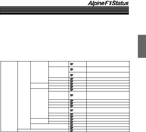
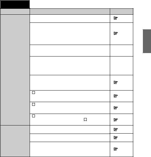
See the reference page in the following chart for the head unit setting/adjustment operation method. The following is displayed on the head unit display.
|
CROSSOVER |
Page 42 |
Crossover adjustment/Switching the phase |
|
|
|
Page 21 |
Performing time correction automatically |
|
|
|
(Automated Time Correction) |
||
MOBILE.S.MGR |
TCR |
|
||
Page 26 |
Performing time correction manually |
|||
|
|
|||
|
|
(Time Correction) |
||
|
|
|
||
|
EQ |
Page 32 |
Equalizer adjustments |
|
|
Road EQ |
Page 15 |
Using the Road Equalizer function |
|
MEDIA.S.MGR |
MX |
Page 47 |
MX settings |
|
DVD LEVEL |
Page 74 |
Adjusting the DVD level |
||
|
||||
|
BI PHANTOM |
Page 60 |
Adjusting the acoustic image |
|
|
|
|
Mixing the Bass Sound of the Center |
|
AP SETUP |
C.BASS SPLIT |
Page 63 |
Channel with the Sound of the Front Left |
|
|
|
and Right Channels |
||
M.M.Manager |
|
|
||
|
REAR MIX |
Page 66 |
Mixing bass sound to the rear channel |
|
MULTI.CH.MGR |
LISTEN MODE |
Page 72 |
Achieving powerful high volume sound |
|
|
OUTPUT LEVEL |
Page 57 |
Adjusting the speaker levels |
|
|
REAR FILL |
Page 69 |
Outputting the Front Channel Signals |
|
|
from the Rear Channels |
|||
|
|
|
||
|
6.1CH MODE |
Page 77 |
6.1-Channel Settings |
|
|
PCM OUT MODE |
Page 80 |
PCM Output Settings |
|
SP SETUP |
SP SELECT |
Page 7 |
Setting the speakers |
|
Dolby SP |
Page 53 |
Speaker setup |
||
|
||||
PRESET |
|
Page 93 |
Storing settings in the memory |
|
|
Page 96 |
Calling out stored values |
||
|
|
|||
AUX SETUP |
|
Page 91 |
External input settings |
•If operating with the head unit’s buttons, view the head unit’s display. If operating from the remote control supplied with the head unit, view the monitor’s display (sold separately) used in the system. If a monitor is not used in your system, operate from the head unit only.
•For how to connect, refer to the guide for installation and connections.
5-EN
Basic Operation
Using This Manual
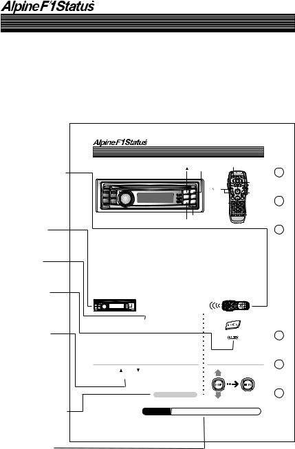
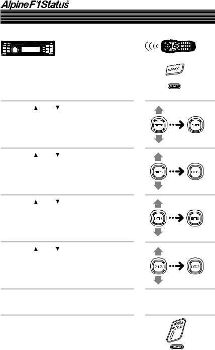
The PXI-H990 is operated from the head unit with which it is used.
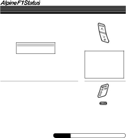
These operating instructions describe operation from both the DVI-9990 head unit and from the RUE-4196 remote control unit included with the head unit. When operating the main unit with the remote control supplied with the head unit, change the selector switch on the rear side of remote control to the “H/U” side.
Remote control icon
Indicates operations performed with the remote control supplied with the head unit (only when connected to
a monitor, sold separately).
Using the multi-channel function
|
|
A. PROC. |
1( |
) |
2(ENT) |
|
|
ENTER/ |
|
|
Joystick |
|
|
/ |
|
|
MENU |
|
|
SETUP |
RETURN |
F • SETUP 5( )
)
Head unit icon
Indicates operations performed from the head unit.
Button name
Buttons to be operated are indicated in bold.
3Sec icon
Indicates that the specified button should be pressed and held for over 3 seconds.
Separately sold monitor display
If you combine with a separately sold monitor and operate with the remote control supplied with the head unit, the selected item is displayed on the screen, as opposed to being displaying on the
head unit.
Continued (Next page)
Indicates that the description of the operation continues on the next page.
Supplement icon
Indicates that there is supplementary information on another page.
Adjusting the acoustic image (BI PHANTOM)
To achieve sound with a sense of presence, the center speaker must be placed directly in front of the driver’s seat and the passenger’s seat. With this function, the center channel information is distributed to the left and right speakers. This creates an acoustic image simulating a center speaker directly in front of the listener. (This only has an effect when “DOLBY PL II MOVIE” or “Neo:6 CINEMA” is selected at “PCM Output Settings” (page 80). The audio source must be playing back Dolby Digital or DTS signals with center channel information.)
•Avoid stopping, pausing, switching the disc, cueing, fast-forwarding or switching the audio channel of the player while making this adjustment.
1 Press and hold F • SETUP for at least 3 seconds.
2 Press 1 ( ) or 5 ( ), select “M.M.Manager [Multi Media Manager]”, then press 2 (ENT).
Continued
Supplement See page 88 for supplementary information.
60-EN
6-EN
1( ) |
2(ENT) |
A. PROC. |
|
|
|
|
|
 ENTER/
Joystick


 MENU
MENU
SETUP
RETURN
F • SETUP 5( )
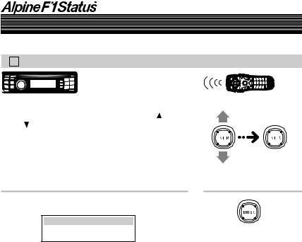
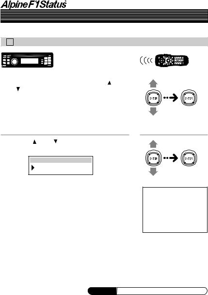
Turning the power on and off
This unit does not have a power switch. The head unit to which the unit is connected, controls its power. In order to protect the speakers when the power is first switched on or when the head unit is reset, no sound is produced until system is selected in the next item “Setting the speakers”. Set the following item “Setting the speakers”.
Setting the speakers (SP SELECT)
First, make the system and speaker settings. The system settings are required before any other settings can be made. To prevent speaker damage, make sure the selected system and speaker connections are in correct (see the instruction manual). It is necessary to check the speaker connection before selecting the system.
Turn off speaker channels that are not in use.
1 Press and hold F • SETUP for at least 3 seconds.
2 Press 1 ( ) or 5 ( ), select “M.M.Manager [Multi Media Manager]”, then press 2 (ENT).
Continued
7-EN
Basic Operation
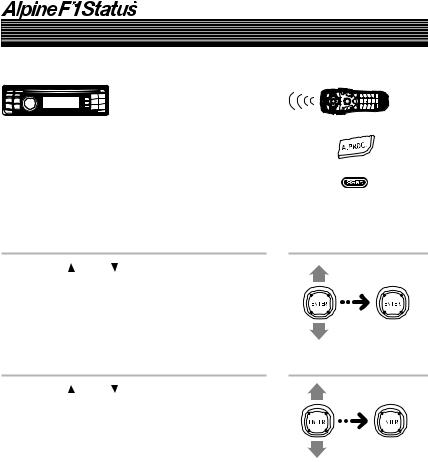
Setting the speakers (SP SELECT) (continued)
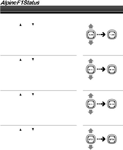
3 Press 1 ( ) or 5 ( ), select “AP SETUP”, then press 2 (ENT).
4 Press 1 ( ) or 5 ( ), select “SP SETUP [Speaker Setup]”, then press 2 (ENT).
5 Press 1 ( ) or 5 ( ), select “SP SELECT [Speaker Select]”, then press 2 (ENT).
6 Press 1 ( ) or 5 ( ), select “SYSTEM SEL [System Select]”, then press 2 (ENT).
8-EN
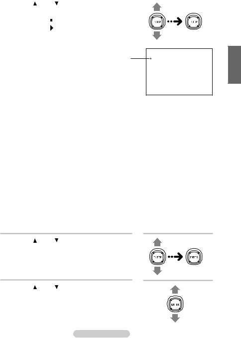
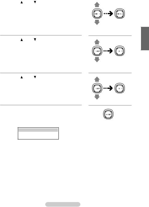
7 Press 1 ( ) or 5 ( ), select the system, then press 2 (ENT).
|
|
|
|
|
|
|
|
|
|
|
|
|
|
Displays the |
|
|
SYSTEM SEL |
|
|
|
|
||||
|
|
|
SYSTEM 1 |
|
|
|||||||
|
currently set |
|
|
|
|
|
|
|||||
|
item. |
|
|
|
|
|
|
|
|
|
|
|
|
|
|
|
|
|
|
|
|
|
|
|
|
|
|
|
|
|
|
|
|
|
|
|
|
|
|
|
|
|
|
|
|
|
|
|
|
|
|
|
When one PXI-H990 is connected |
When two PXI-H990 are connected |
|
|||||||||
|
|
|
|
|
|
|
|
|
|
|
|
|
|
SYSTEM 1 |
SYSTEM 2 |
SYSTEM 3 |
SYSTEM 4 (FRONT) |
SYSTEM 4 (REAR) |
|
||||||
|
|
|
|
|
|
|
|
|
|
|
|
|
CH-1 |
F TW L |
F TW L |
FRNT L*1 |
F TW L |
R TW L |
|
||||||
|
|
|
|
|
|
|
|
|
|
|
|
|
CH-2 |
F TW R |
F TW R |
FRNT R*1 |
F TW R |
R TW R |
|
||||||
|
|
|
|
|
|
|
|
|
|
|
|
|
CH-3 |
F WF L*1 |
F MID L*2 |
FRNT C |
F MID L*2 |
R WF L |
|
||||||
|
|
|
|
|
|
|
|
|
|
|
|
|
CH-4 |
F WF R*1 |
F MID R*2 |
SUBW. 1 |
F MID R*2 |
R WF R |
|
||||||
|
|
|
|
|
|
|
|
|
|
|
|
|
CH-5 |
REAR L |
F WF L*2 |
REAR L |
F WF L*2 |
R TW C |
|
||||||
|
|
|
|
|
|
|
|
|
|
|
|
|
CH-6 |
REAR R |
F WF R*2 |
REAR R |
F WF R*2 |
R WF C |
|
||||||
|
|
|
|
|
|
|
|
|
|
|
|
|
CH-7 |
FRNT C |
SUBW. 1 |
REAR C |
F TW C |
SUBW. 1 |
|
||||||
|
|
|
|
|
|
|
|
|
|
|
|
|
CH-8 |
SUBW. |
SUBW. 2 |
SUBW. 2 |
F WF C |
SUBW. 2 |
|
||||||
|
|
|
|
|
|
|
|
|
|
|
|
|
*1 There is no OFF setting.
*2 It is not possible to turn both “MID” and “WF” off.
If one is set to “OFF”, the other cannot be set to “OFF”.
•Do not connect the tweeter (TW) to the channel without “TW” indicated in the table above. If connected, the speaker may be damaged.
•For SYSTEM 1, REAR TW cannot be connected.
•For SYSTEM 3, FRONT TW and REAR TW cannot be connected.
•“SYSTEM 4” cannot be selected when only one unit of the PXI-H990 is connected. Also, “SYSTEM 1” to “SYSTEM 3” cannot be selected when two units of the PXI-H990 are connected.
Next make the speaker settings.
8 Press 1 ( ) or 5 ( ), select “CH SELECT [Channel Select]”, then press 2 (ENT).
9 Press 1 ( ) or 5 ( ), select the speaker that is not connected, then press 2 (ENT).
Continued
 SYSTEM SEL
System 1
System 2
System 3
System 4
Select a speaker that is not connected.
9-EN
Basic Operation
Setting the speakers (SP SELECT) (continued)
10Press 1 ( ) or 5 (
 ), select “OFF”, then press
2 (ENT).
Repeat steps 9 and 10 and switch off all unconnected speakers.
 CH SELECT
F TW L OFF
11Once the settings are completed, press and hold F • SETUP for at least 3 seconds.
•Press 6 (RTN) or RETURN on the remote control in the setting mode to return to the previous item.
Switch ON/OFF.
 CH SELECT
Front TW Left ON
Front TW Right ON
Front WF Left ON
Front WF Right ON
Rear Left ON
Rear Right ON
Front Center ON
Subwoofer ON
Supplement See page 11 for supplementary information.
10-EN

Supplementary |
This page includes supplementary information for pages 5 to 10. |
|
information |
Please refer to these pages. |
TITLE |
Description |
Setting the speakers |
The operations performed with the remote control unit in |
(SP SELECT) |
step 1 can also be performed by pressing MENU (SETUP) |
|
for at least 3 seconds, moving the joystick up or down to |
|
select “AP SETUP”, then pressing the joystick. |
|
|
Related page
 Page 7
11-EN

Automatic Adjustments
Preparations for automatic adjustments
The PXI-H990 is equipped with two automatic adjustment functions: “Road Equalizer” and “Automated Time Correction”.
The preparations described below must be made in order to perform these automatic adjustments. After making these preparations, refer to “Automatic adjustments (Using the Road Equalizer function)” (page 15) and “Performing time correction automatically (Automated Time Correction)” (page 21) to perform the respective automatic adjustments.
• When performing automatic adjustment, set the head unit to the TUNER mode before adjusting.
1 Check that the head unit defeat mode is off.
2 Adjust the head unit and amplifier levels.
Head unit:
Set the balance and fader to “center”.
Front, rear and center amplifiers:
Set the amp gains to “center” or “normal” to start. If there are no rear speakers, check that the rear speakers are turned off. (See page 7.) Gain levels may be changed if you are not satisfied with the automatic results. Make the gain changes and return the automatic adjustment.
Subwoofer amplifier:
Set the amplifier gain to “center” or “normal”. If the subwoofer is located in the trunk or a remote place (for example at the very back of a station wagon), adjust the subwoofer to increase the volume several steps.
Speaker Crossovers:
Set the crossovers for all the speakers in the system that will require them. See page 42, “Crossover adjustment/Switching the phase”, for more information on setting the crossovers.
12-EN
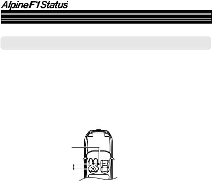
3 Connect the included microphone to the PXI-H990. Refer to the Installation manual.
•When combined with a separately sold monitor that is Road EQ compatible and the Road Equalizer function are used, the separately sold monitor’s built-in microphone can be used.
•When connecting two PXI-H990 units, connect the microphone to both units. In this case, the built-in microphone in the separately sold monitor cannot be used.
4 Secure the microphone in place.
Failure to fix the microphone securely in place may result in distortion or improper acoustic positioning. The microphone must be mounted very securely so the bass frequencies will not vibrate it. For example, fasten using the fitting included with the sun visor, etc.
•The adjustment differs according to the position
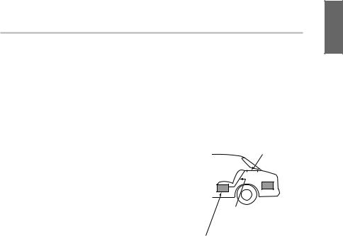
of the microphone. Search for the position at which the desired sound quality can be achieved.
•The proper adjustments cannot be achieved if the subwoofer is located in the trunk and the trunk and cabin are separated by a metal sheet. Either move the subwoofer into the cabin or open a hole in the
rear tray to join the two spaces. (This is not necessary if the partition is not a metal sheet.)
If the partition is a metal sheet, open a hole in the rear tray.
If you encounter a problem, consult your authorized dealer.
Is the partition a metal sheet?
Or move the subwoofer into the cabin.
• Do not disconnect the microphone during the automatic adjustment procedure.
13-EN
Automatic Adjustments
Preparations for automatic adjustments (continued)
Hints on using the Road Equalizer function
The Road Equalizer compensates for constantly changing noise, so always keep the microphones connected. The following three places are recommended to place the microphones. Also, when combining with the separately sold monitor, the built-in microphone can be used.
ACeiling directly above the listening position (driver’s seat position – More accurate compensation for the driver.)
BSun visor (driving seat position)
CBase of rearview mirror (position for both driver’s and passenger’s seats)
C |
B |
A |
•If connecting two PXI-H990 units, place the microphones connected to each unit in the same places.
14-EN

1( ) 2(ENT) |
A. PROC. |
 ENTER/
Joystick


 MENU
MENU
SETUP
RETURN
5( ) 6(RTN) F • SETUP
Using the Road Equalizer function
Road Equalizer (REAL-TIME OPTIMIZED ADAPTIVE DRIVING EQUALIZER) is a function that automatically adjusts the equalizer settings during driving according to the amount of road noise.
To use Road Equalizer, first connect the microphone. (See “Preparations for automatic adjustments” on page 12.)
When used in combination with a separately sold monitor that is Road EQ compatible, the monitor’s built-in microphone can be used, in which case the microphone included with the PXIH990 cannot be used. When connecting two PXI-H990 units, the built-in microphone in the separately sold monitor cannot be used.
Perform the Road Equalizer operations in the following order:
ASelection of microphone
↓
BMeasurement of frequency
response inside the vehicle
↓
CSelection of Road Equalizer setting
(ON/OFF)
↓
DSelection of mode
•In order to avoid the effects of exterior noises during measurement of frequency response inside the vehicle, move the car to a quiet location and change the ignition switch to the ACC position.
Due to vibration, correct measurement data may not be acquired, so do not switch on the engine. However, be aware that the battery may be drained.
•Do not remove the microphones when using Road Equalizer.
Supplement See page 25 for supplementary information.
15-EN
Automatic Adjustments
Using the Road Equalizer function (continued)
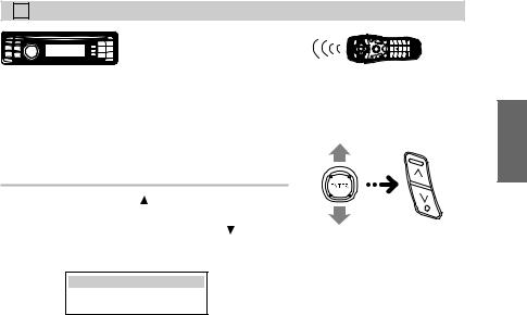
1 Press and hold F • SETUP for at least 3 seconds.
2 Press 1 ( ) or 5 ( ), select “M.M.Manager [Multi Media Manager]”, then press 2 (ENT).
3 Press 1 ( ) or 5 ( ), select “AP SETUP”, then press 2 (ENT).
4 Press 1 ( ) or 5 ( ), select “MOBILE.S.MGR [Mobile Sound Manager]”, then press 2 (ENT).
5 Press 1 ( ) or 5 ( ), select “Road EQ”, then press 2 (ENT).
6 Perform the operations from page 17 to 20.
7 Press and hold F • SETUP for at least 3 seconds to end.
16-EN
A Selecting the Microphone
1) In the Road Equalizer mode, press 1 ( ) or 5 ( ), select “MIC SELECT [Microphone Select]”, then press 2 (ENT).
2)Press 1 ( ) or 5 ( ), select the microphone, then press 2 (ENT).
 MIC SELECT
 EXTERNAL MIC
EXTERNAL MIC [External Microphone]:
Set this when using the microphone included with the PXI-H990.
MONITOR MIC [Monitor Internal Microphone]:
Set this when using in combination with a separately sold monitor (TMI-M990) and using the monitor’s built-in microphone.
Next measure the frequency response inside the vehicle.
•Press 6 (RTN) or RETURN on the remote control in the setting mode to return to the previous item.
 MIC SELECT

 External Microphone
Monitor Internal Microphone
 Displays the currently set item.
Supplement See page 25 for supplementary information.
17-EN
Automatic Adjustments
Using the Road Equalizer function (continued)
B Measuring the Frequency Response Inside the Vehicle
1)In the Road Equalizer mode, press 1 ( ) or 5 ( ), select “R.EQ SETUP [Auto Road EQ
Setup]”, then press 2 (ENT).
2) Press 2 (ENT).
 R.EQ SETUP
START
Measuring begins after a 10 second countdown, so leave the car and close the door within 10 seconds.
Measuring is canceled if 2 (ENT) is pressed during measuring or during the countdown. Measuring ends after about 8 minutes. After measuring is complete, “COMPLETE” is displayed, press 2 (ENT) to clear measuring mode and press 6 (RTN).
•Press 6 (RTN) or RETURN on the remote control in the setting mode to return to the previous item.
•“NO MIC ERR” is displayed when a microphone has not been connected. Press 2 (ENT) to clear the display.
After measuring is complete, “Complete” is displayed, press ENTER to clear measuring mode and press RETURN.
•“NO MIC ERR” is displayed when a microphone has not been connected. Press ENTER to clear the display.
18-EN
C Turning Road Equalizer On and Off
1)In the Road Equalizer mode, press 1 ( ) or 5 (
 ), select “Road EQ ON/OFF”.
2) When OFF, press 1 ( ) after pressing
2 (ENT) to switch ON.
To switch from ON to OFF, press 5 ( ) after pressing 2 (ENT).
 Road EQ
Road EQ ON
Select “OFF” if you do not want to use the
Road Equalizer function.
•Press 6 (RTN) or RETURN on the remote control in the setting mode to return to the previous item.
19-EN
Automatic Adjustments
Using the Road Equalizer function (continued)
D Selecting the Mode
1)In the Road Equalizer mode, press 1 ( ) or 5 ( ), select “MODE SELECT”, then press
2 (ENT).
2)Press 1 ( ) or 5 ( ), select the desired mode, then press 2 (ENT).
 MODE SELECT
MODE1
MODE1 [Mode1]: Low compensation mode. Suitable for a quiet car.
MODE2 [Mode2]: Higher compensation mode.
MODE3 [Mode3]: Highest compensation mode. Use when driving in a very noisy car.
 MODE SELECT
 Mode1
Mode1
Mode2
Mode3
•Press 6 (RTN) or RETURN on the remote control in the setting mode to return to the previous item.
Supplement See page 25 for supplementary information.
20-EN

1( ) 2(ENT) |
A. PROC. |
 ENTER/
Joystick


 MENU
MENU
SETUP
RETURN
5( ) 6(RTN) F • SETUP
Performing time correction automatically (Automated Time Correction)
Due to the particular conditions inside the vehicle, there is a major difference between the distances of the various speakers and the listening position. This function uses the included measurement microphone to automatically measure and analyze the distances between the speakers and the listening position and perform the optimum time correction.
•Preparations must be made before performing the automatic adjustment procedure. Refer to page 12.
•The PXI-H990’s automatic adjustments take into account the delay time between the time at which the signals are input to the speakers until the sound is output. This does not correspond to the actual distance.
•With the automatic adjustments, the average delay time within the speakers’ playable frequency range is measured. Measurements may not be possible when using special speakers or in special playback environments. If this is the case, perform the adjustments manually.
•The AUTO TCR operation cannot be performed if the included microphone is not connected.
•When performing automatic adjustment, set the head unit to the TUNER mode before adjusting.
1Before starting the automatic adjustment procedure, park the vehicle in a quiet place to avoid the effects of external sounds.
2Set the vehicle’s key to the ACC position.
Do not start the engine. The vibrations may make it impossible to achieve the proper adjustment values.
3Adjust the volume.
Adjust the volume to “-50dB” by performing the volume adjustment operation on the head unit.
Continued
21-EN
Automatic Adjustments
Performing time correction automatically (Automated Time Correction) (continued)
4 Press and hold F • SETUP for at least 3 seconds.
5 Press 1 ( ) or 5 ( ), select “M.M.Manager [Multi Media Manager]”, then press 2 (ENT).
6 Press 1 ( ) or 5 ( ), select “AP SETUP”, then press 2 (ENT).
22-EN
7 Press 1 ( ) or 5 ( ), select “MOBILE.S.MGR [Mobile Sound Manager]”, then press
2 (ENT).
8 Press 1 ( ) or 5 ( ), select “TCR [Time Correction]”, then press 2 (ENT).
9 Press 1 ( ) or 5 ( ), select “AUTO TCR [Auto Time Correction]”, then press 2 (ENT).
•Check that “TCR” is set to “ON”.
If it is set to “OFF”, set it to “ON”, referring to “Performing time correction manually” on page 26.
10Press 2 (ENT).
Automatic adjustment begins after a 10 second countdown, so leave the car and close the door within 10 seconds.
 AUTO TCR
START...
Automatic adjustment is canceled if 2 (ENT) is pressed during the countdown.
Continued
23-EN

Automatic Adjustments
Performing time correction automatically (Automated Time Correction) (continued)
The automatic adjustment procedure consists of the operations described below and requires about a few minutes to be completed.
Perform the time correction.
When the automatic adjustment is completed, a system reset will be performed.
Strong sounds are produced during the automatic adjustment procedure (except for TW, Sub WF). These sounds can be heard outside the vehicle. Be sure to park the vehicle in a place where the sound will not be a nuisance.
• “NO MIC ERR” is displayed when a microphone has |
|
• “NO MIC ERR” is |
not been connected. Press 2 (ENT) to clear the |
|
displayed when a |
display. |
|
microphone has not been |
|
|
connected. Press ENTER |
|
|
to clear the display. |
|
|
|
11When the system reset is completed, return to |
|
|
the car and check that the setting value of the |
|
|
Automated Time Correction is reflected. |
|
|
If the setting value is not changed, the |
|
|
microphone may not receive sound, the |
|
|
speaker may be damaged, the connection |
|
|
and wiring may be a malfunction. |
|
|
To store the settings, refer to “Storing settings |
|
|
in the memory” (page 93). |
|
|
• Press 6 (RTN) or RETURN on the remote control in |
|
|
the setting mode to return to the previous item. |
|
|
Supplement See page 25 for supplementary information.
24-EN
Supplementary This page includes supplementary information for pages 12 to 24. information Please refer to these pages.
TITLE |
Description |
Related page |
Using the Road |
Connect both microphones if two PXI-H990s are connected. |
Page 15 |
Equalizer function |
|
|
|
|
If the microphone does not pick up the sound or the speakers are not working or are connected or wired
improperly, the automatic adjustments are not performed
Page 15
and a warning message is displayed.
Check the various speakers then perform the automatic adjustments again.
When Road Equalizer is ON and 96 kHz or 192 kHz DVD-
Audio playback is set, down sampling to 48 kHz will take  Page 15 place automatically and the DVD will be played.
When any speaker is switched on or off following the adjustment of Road Equalization and Road Equalization is
ON, Road Equalization will automatically be switched OFF.  Page 15 When a change has been made to the speaker settings,
redo the setup from the measurement step.
The operations performed with the remote control unit in
step 1 can also be performed by pressing and holding
Page 16
MENU (SETUP) for at least 3 seconds, moving the joystick up or down to select “AP SETUP”, then pressing the joystick.
|
B Measuring the Frequency Response Inside the Vehicle |
|
|
|
Note that using for extended periods of time without turning |
Page 18 |
|
|
on the engine may wear down the battery. |
|
|
|
C Turning Road Equalizer On and Off |
|
|
|
The mode is automatically set to “ON” when the frequency |
Page 19 |
|
|
response inside the vehicle is measured. |
|
|
|
D Selecting the Mode |
|
|
|
Cannot be selected when OFF is set in “ C Turning Road |
Page 20 |
|
|
Equalizer On and Off”. |
|
|
Performing time |
Connect both microphones if two PXI-H990s are connected. |
Page 21 |
|
correction automati- |
|
||
|
|
||
cally |
Note that using for extended periods of time without turning |
Page 21 |
|
(Automated Time |
|||
on the engine may wear down the battery. |
|||
Correction) |
|
||
|
|
The operations performed with the remote control unit in
step 4 can also be performed by pressing and holding
Page 22
MENU (SETUP) for at least 3 seconds, moving the joystick up or down to select “AP SETUP”, then pressing the joystick.
25-EN

Settings/Adjustments
Performing time correction manually (Time Correction)
Though sufficient correction can be achieved with the “Automated Time Correction” automatic adjustments, it is also possible for the user to calculate the correction values and make the adjustments manually. This manual adjustment requires sufficient knowledge and experience, however, so we suggest you have it performed at your authorized Alpine dealer.
1 Check that the head unit defeat mode is off.
2 Sit in the listening position (the driver’s seat, for example) and measure the distance (in meters) between your head and the various speakers.
3 Calculate the difference in distance between the farthest speaker and the other speakers.
L = (distance of farthest speaker) – (distance of other speakers)
26-EN
 Loading...