


Intelligent CableUPS®
Technical Manual
XM2, XM2-HV, XM2-HP
Effective: January 2013

PowerAlpha Technologies 


 ®
®

Intelligent CableUPS® Technical Manual
017-805-B0-010, Rev K2
Effective Date: January 2013
Copyright © 2013
Alpha Technologies, Inc.
NOTE:
Photographs contained in this manual are for illustrative purposes only. These photographs may not match your installation.
NOTE:
Operator is cautioned to review the drawings and illustrations contained in this manual before proceeding. If there are questions regarding the safe operation of this powering system, please contact Alpha Technologies or your nearest Alpha representative.
NOTE:
Alpha shall not be held liable for any damage or injury involving its enclosures, power supplies, generators, batteries or other hardware if used or operated in any manner or subject to any condition not consistent with its intended purpose or is installed or operated in an unapproved manner or improperly maintained.
Notice of FCC Compliance
Per FCC 47 CFR 15.21:
Changes or modifications not expressly approved by the party responsible for compliance could void the user’s authority to operate the equipment.
Per FCC 47 CFR 15.105:
This equipment has been tested and found to comply with the limits for a Class A digital device, pursuant to part 15 of the FCC Rules. These limits are designed to provide reasonable protection against harmful interference when the equipment is operated in a commercial environment. This equipment generates, uses and can radiate radio frequency energy and, if not installed and used in accordance with the instruction manual, may cause harmful interference to radio communications. Operation of this equipment in a residential area is likely to cause harmful interference in which case the user will be required to correct the interference at their own expense.
Contacting Alpha Technologies: www.alpha.com
or
For general product information and customer service (7 AM to 5 PM, Pacific Time), call
1-800-863-3930
For complete technical support, call
1-800-863-3364
7 AM to 5 PM, Pacific Time or 24/7 emergency support
017-805-B0-010 Rev. K2 |
3 |
Table of Contents
Safety Notes |
...................................................................................................................... |
|
8 |
|
Safety Precautions............................................................................................................ |
|
8 |
||
Battery Safety .........................................................................................................Notes |
9 |
|||
Utility Power .......................................................................................Connection Notes |
10 |
|||
Grounding and .........................................................................Earth Connection Notes |
13 |
|||
1.0 |
Introduction........................................................................................................... |
|
14 |
|
|
1.1 ................................................................................... |
Theory of Operation |
15 |
|
|
........................................................................ |
1.1.1 |
AC (Line) Operation |
15 |
|
.......................................................................... |
1.1.2 |
Standby Operation |
16 |
|
.......................................................................... |
1.1.3 |
Charger Operation |
17 |
|
1.2 ...................................................................... |
Intelligent CableUPS Layout |
18 |
|
|
....................................................... |
1.2.1 |
Transformer Module Overview |
18 |
|
............................................................... |
1.2.2 |
Inverter Module Overview |
19 |
|
.............................................. |
1.2.3 Optional Status Monitoring Modules |
22 |
|
|
1.3 ............................................... |
Recommended Enclosure System Options |
23 |
|
2.0 |
Installation............................................................................................................ |
|
25 |
|
|
2.1 ................................................................................ |
Installation Procedure |
25 |
|
|
2.2 ..................................................... |
Installing the Optional Indicator Lamps |
26 |
|
|
.......................................................................... |
2.2.1 |
AC Indicator Lamp |
26 |
|
................................................................... |
2.2.2 |
Local/Remote Indicator |
27 |
|
2.3 ............................................................................................ |
Initial Turn Up |
29 |
|
|
2.4 ................................................. |
Inverter Module Removal and Installation |
30 |
|
|
2.5 ............................................................. |
Protective Interface Module (PIM) |
31 |
|
|
2.6 ....................................................................................... |
Installing the PIM |
32 |
|
|
2.7 ................................................................................ |
Programming the PIM |
35 |
|
|
............................................................................. |
2.7.1 |
The Setup Menu |
36 |
|
2.8 .................................................................................... |
N+1 Configurations |
37 |
|
|
2.9 ..................................................................... |
Service Power Inserter (SPI) |
39 |
|
3.0 |
Configuration........................................................................................................ |
|
41 |
|
|
3.1 ...................................................... |
Power Distribution Board (PDB) Setup |
41 |
|
|
................................. |
3.1.1 |
Replacing the Metal Oxide Varistors (MOVs) |
44 |
|
................................................. |
3.1.2. Replacing the Line Isolation Relay |
45 |
|
|
3.2 ............................................................. |
AC Input Voltage Reconfiguration |
46 |
|
|
.............................................. |
3.2.1 |
Reconfiguration from 120 to 240Vac |
46 |
|
.............................................. |
3.2.2 |
Reconfiguration from 240 to 120Vac |
48 |
|
3.3 ........................................................... |
AC Output Voltage Reconfiguration |
50 |
|
|
........................................... |
3.3.1 |
Output Voltage Switch (SW1) Settings |
51 |
4 |
017-805-B0-010 Rev. K2 |
Contents, continued
4.0 |
Operation.............................................................................................................. |
|
53 |
|
|
4.1 |
Start-up and Test....................................................................................... |
53 |
|
|
|
4.1.1 |
AC Line Operation.......................................................................... |
53 |
|
|
4.1.2 |
Self Test Operation......................................................................... |
54 |
|
|
4.1.3 |
Standby Operation ......................................................................... |
55 |
|
4.2 |
Using the Smart Display............................................................................ |
56 |
|
|
4.3 |
Smart Display Modes................................................................................ |
58 |
|
|
|
4.3.1 |
Operation Normal........................................................................... |
58 |
|
|
4.3.2 Comms Information Display (with DSM2 or later)........................... |
59 |
|
|
|
4.3.3 |
Setup Menu.................................................................................... |
60 |
|
|
4.3.4 Menu Structure/Navigation (from Operation Normal screen)......... |
63 |
|
|
|
4.3.5 Menu Structure/Navigation (from Active Alarms screen)................ |
64 |
|
|
4.4 |
Alarm Indications....................................................................................... |
65 |
|
|
4.5 |
Smart Display LEDs.................................................................................. |
71 |
|
|
4.6 |
Smart Display Glossary............................................................................. |
72 |
|
|
4.7 |
Automatic Performance Test..................................................................... |
74 |
|
|
4.8 |
Providing Power via Portable Generator or Inverter.................................. |
75 |
|
|
|
4.8.1 |
DC Powering................................................................................... |
75 |
|
|
4.8.2 |
AC Powering................................................................................... |
75 |
|
|
4.8.3 Using a Truck-mounted Inverter or Generator................................ |
76 |
|
|
4.9 |
Resumption of Utility Power...................................................................... |
77 |
|
5.0 |
Intelligent CableUPS Maintenance....................................................................... |
78 |
||
|
5.1 |
System Information.................................................................................... |
78 |
|
|
5.2 |
Battery Charger Voltage............................................................................ |
79 |
|
|
5.3 |
Battery Terminals and Connecting Wires.................................................. |
79 |
|
|
5.4 |
Output Voltage........................................................................................... |
79 |
|
|
5.5 |
Output Current........................................................................................... |
79 |
|
|
5.6 |
Check Output Connections........................................................................ |
79 |
|
|
|
5.6.1 |
Visual Inspection............................................................................. |
79 |
|
5.7 |
Inverter Module Maintenance.................................................................... |
80 |
|
|
5.8 |
Maintenance Log....................................................................................... |
81 |
|
|
5.9 |
Repair Record........................................................................................... |
82 |
|
6.0 |
Specifications....................................................................................................... |
83 |
||
|
6.1 |
Intelligent CableUPS North American Models........................................... |
83 |
|
|
6.2 |
Intelligent CableUPS International Models................................................ |
84 |
|
|
6.3 |
Safety and EMC Compliance.................................................................... |
85 |
|
7.0 Return and Repair Information............................................................................. |
86 |
|||
|
7.1 |
Emergency Shutdown............................................................................... |
87 |
|
017-805-B0-010 Rev. K2 |
5 |
Figures and Tables |
|
Fig. 1-1, XM2-HP Power Supply........................................................................................................... |
15 |
Fig. 1-2, Standard XM2 Power Supply................................................................................................. |
15 |
Fig. 1-3, Simplified Block Diagram....................................................................................................... |
16 |
Fig. 1-4, Charger Modes....................................................................................................................... |
17 |
Fig. 1-5, Transformer Module Connections.......................................................................................... |
18 |
Fig. 1-6, Inverter Module Voltage Rating Labels.................................................................................. |
19 |
Fig. 1-7, Inverter Module Connections................................................................................................. |
20 |
Fig. 1-8, Placement of Remote Temperature Sensor (RTS) on battery................................................ |
21 |
Fig. 1-9, Placement of Battery Spacer Clips on 36V and 48V battery strings...................................... |
21 |
Fig. 1-10, DSM3x.................................................................................................................................. |
22 |
Fig. 1-11, IDH3...................................................................................................................................... |
22 |
Fig. 1-12, Standard AlphaGuard........................................................................................................... |
24 |
Fig. 1-13, Potted AlphaGuard............................................................................................................... |
24 |
Fig. 2-1, AC Indicator Lamp.................................................................................................................. |
26 |
Fig. 2-2, Wire/Housing Assembly......................................................................................................... |
26 |
Fig. 2-3, Local/Remote Indicator Lamp................................................................................................ |
27 |
Fig. 2-4, Wire/Housing Assembly......................................................................................................... |
27 |
Fig. 2-5, ACI/LRI Connection................................................................................................................ |
28 |
Fig. 2-6, Inverter Module Ribbon Cable................................................................................................ |
30 |
Fig. 2-7, Detail of Locking Mechanism................................................................................................. |
30 |
Fig. 2-8, PDB Connections................................................................................................................... |
32 |
Fig. 2-9, J6 and J4 connection as seen from rear of Power Distribution Board................................... |
33 |
Fig. 2-10, Location of JP1 on PIM........................................................................................................ |
34 |
Fig. 2-11, Jumper in 15A position......................................................................................................... |
34 |
Fig. 2-12, Jumper in 22A position......................................................................................................... |
34 |
Fig. 2-13, PIM (Protective Interface Module) and PDB (Power Distribution Board)............................. |
34 |
Fig. 2-14, N+1 Configuration................................................................................................................ |
37 |
Fig. 2-15, Dual Redundancy (N+1) Configuration................................................................................ |
38 |
Fig. 2-16, SPI Cover Removal.............................................................................................................. |
39 |
Fig. 2-17, Coaxial Cable Insertion and Securing.................................................................................. |
39 |
Fig. 2-18, Cover Replaced, SPI Switched On...................................................................................... |
40 |
Fig. 2-19, SPI Grounding Lug............................................................................................................... |
40 |
6 |
017-805-B0-010 Rev. K2 |

Figures and Tables, continued |
|
Fig. 2-20, Enclosure Ground Bar.......................................................................................................... |
40 |
Fig. 3-1, Locations of JP1, JP2 and SW1, SW2 on the Power Distribution Board (PDB).................... |
42 |
Fig. 3-2, MOV Replacement................................................................................................................. |
44 |
Fig. 3-3, Typical NEMA Receptacles and Plugs................................................................................... |
46 |
Fig. 3-4, Transformer Module Input Jumpers, PDB Jumpers............................................................... |
47 |
Fig. 3-5, SW2 Settings.......................................................................................................................... |
47 |
Fig. 3-7, Transformer Module Input Jumpers, PDB Jumpers............................................................... |
48 |
Fig. 3-6, Typical NEMA Receptacles and Plugs................................................................................... |
48 |
Fig. 3-8, SW2 Settings.......................................................................................................................... |
49 |
Fig. 3-9, XM2-615A Transformer Output Tap Connector shown in default setting (63Vac).................. |
50 |
Fig. 3-10, Transformer Output Tap Connector for other XM Series 2 Power Supplies......................... |
50 |
Fig. 4-1, Configuration Screen.............................................................................................................. |
53 |
Fig. 4-2, Smart Display Navigation....................................................................................................... |
56 |
Fig. 4-3, Smart Display Panel............................................................................................................... |
57 |
Fig. 4-4, Operation Normal Display...................................................................................................... |
58 |
Fig. 4-5, Comms Information Display................................................................................................... |
59 |
Fig. 4-6, Setup Menu Display .............................................................................................................. |
62 |
Fig. 4-7, Output and Alarm LEDs.......................................................................................................... |
71 |
Fig. 7-1 Emergency Shutdown............................................................................................................. |
87 |
Table 3-1, Power Distribution Board Setup........................................................................................... |
43 |
Table 3-2, Output Voltage switch settings per Power Supply............................................................... |
51 |
Table 3-3, Output Voltage switch settings for XM2-918HP, XM2-924HP.............................................. |
52 |
Table 4-1, AC Output............................................................................................................................ |
54 |
Table 6-1 Specifications for North American Models............................................................................ |
83 |
Table 6-2 Specifications for International Models................................................................................. |
84 |
Table 6-3, Product Certifications........................................................................................................... |
85 |
017-805-B0-010 Rev. K2 |
7 |

Safety Notes
Review the drawings and illustrations contained in this manual before proceeding. If there are any questions regarding the safe installation or operation of the system, contact Alpha Technologies or the nearest Alpha representative. Save this document for future reference.
To reduce the risk of injury or death and to ensure the continued safe operation of this product, the following symbols have been placed throughout this manual. Where these symbols appear, use extra care and attention.
ATTENTION:
The use of ATTENTION indicates specific regulatory/code requirements that may affect the placement of equipment and/or installation procedures.
NOTE:
A NOTE provides additional information to help complete a specific task or procedure.
CAUTION!
The use of CAUTION indicates safety information intended to PREVENT DAMAGE to material or equipment.
WARNING!
WARNING presents safety information to PREVENT INJURY OR DEATH to the technician or user.
Safety Precautions
•Only qualified personnel may service the Intelligent CableUPS.
•Verify the voltage requirements of the equipment to be protected (load), the AC input voltage to the power supply (line) and the output voltage of the system prior to installation.
•Equip the utility service panel with a properly rated circuit breaker for use with this power supply.
•When connecting the load, DO NOT exceed the output rating of the power supply.
•Always use proper lifting techniques whenever handling units, modules or batteries.
•The power supply contains more than one live circuit! Even though AC voltage is not present at the input, voltage may still be present at the output.
•If batteries are being stored prior to installation, recharge per manufacturer’s specifications to ensure optimum performance and maximum battery service life.
•Reduce the chance of spark and wear on the connectors; always switch the inverter’s battery circuit breaker off before connecting or disconnecting the battery pack
•The battery pack, which provides backup power, contains dangerous voltages. Only qualified personnel should inspect or replace batteries.
•In the event of a short-circuit, batteries present a risk of electrical shock and burns from high current. Observe proper safety precautions.
•Always wear protective clothing, insulated gloves and eye protection (i.e. safety glasses or a face shield) whenever working with batteries.
•Always carry a supply of water, such as a water jug, to wash the eyes or skin in the event of exposure to battery electrolyte.
8 |
017-805-B0-010 Rev. K2 |

Safety Precautions, continued
•Do not allow live battery wires to contact the enclosure chassis. Shorting battery wires can result in a fire or possible explosion.
•Always replace batteries with those of an identical type and rating. Never install old or untested batteries.
•Avoid using uninsulated tools or other conductive materials when handling batteries or working inside the enclosure.
•Remove all rings, watches and other jewelry before servicing batteries.
•Spent or damaged batteries are environmentally unsafe. Always recycle used batteries. Refer to local codes for proper disposition of batteries
•The Intelligent CableUPS has been investigated by regulatory authorities for use in various Alpha enclosures. If you are using a non-Alpha enclosure, it is your responsibility to ensure your combination conforms to your local regulatory requirements and the power supply remains within its environmental specifications.
Battery Safety Notes
•Always refer to the battery manufacturer’s recommendation for selecting correct “FLOAT” and “ACCEPT” charge voltages. Failure to do so can damage the batteries.
•Verify the power supply’s battery charger “FLOAT” and “ACCEPT” charger voltage settings.
•Batteries are temperature sensitive. During extremely cold conditions, a battery’s charge acceptance is reduced and requires a higher charge voltage; during extremely hot conditions, a battery’s charge
acceptance is increased and requires a lower charge voltage. To compensate for changes in temperature, the battery charger used in the power supply is temperature compensating. Refer to Section 1.2.2 for instructions on connecting the Remote Temperature Sensor (RTS).
•If the batteries appear to be overcharged or undercharged, first check for defective batteries and then verify the correct charger voltage settings.
•To ensure optimum performance, inspect batteries every three to six months for signs of cracking, leaking or unusual swelling (note that some swelling is normal).
•Check battery terminals and connecting wires. Clean battery terminal connectors periodically and retighten to approximately 110 inch-pounds (or to manufacturer’s specifications if not AlphaCells). Spray the terminals with an approved battery terminal coating such as NCP-2.
NOTE:
If installed, disconnect the AlphaGuard prior to measuring battery voltage.
NOTE:
Even with a AG-CMT present in the system, any battery which fails the 0.3V load test must be replaced with an identical type of battery.
•Check battery voltages UNDER LOAD. Use a load tester if available. Differences between any battery in the set should not be greater than 0.3Vdc.
•Refer to the battery manufacturer’s recommendation for correct charger voltages and the power supply operation manual for corresponding charger settings.
•Number the batteries (1, 2, 3, etc.) inside the enclosure for easy identification (refer to the appropriate enclosure installation guide).
•Establish and maintain a battery maintenance log.
NOTE:
Always verify proper polarity of cables before connecting the batteries to the power module. The batteries are clearly marked for polarity. If the cables become interchanged at the batteries the battery breaker will trip.
017-805-B0-010 Rev. K2 |
9 |

Utility Power Connection Notes
ATTENTION:
Connecting to the utility should be performed only by qualified service personnel and in compliance with local electrical codes. Connection to utility power must be approved by the local utility before installing the power supply.
UL and NEC require that a service disconnect switch (UL listed) be provided by the installer and be connected between the power source and the ALPHA power supply. Connection to the power supply must include an appropriate service entrance weather head.
NOTE:
In order to accommodate the high-inrush currents normally associated with the start-up of ferroresonant transformers (400 Amp, no-trip, first-half cycle), either a “high-magnetic” or an HACR (Heating,
Air Conditioning, Refrigeration) trip breaker must be used. Do not replace these breakers with a conventional service entrance breaker. Alpha recommends ONLY Square D breakers because of the increased reliability required in this powering application. High-magnetic Square D circuit breakers and a BBX option (UL Listed service entrance) are available from Alpha Technologies.
Description |
Alpha Part Number |
Square D Part Number |
240V Installation - HACR (15A) |
470-224-10 |
QO215 |
120V Installation - High-magnetic (20A) |
470-017-10 |
QO120HM |
BBX - External Service Disconnect |
020-085-10 |
QO2 -4L70RB |
BBX - External Service Disconnect |
020-141-10 |
QO8-16L100RB |
ATTENTION:
In most cases, the following configurations qualify for service entrance use when wiring a duplex receptacle to a service disconnect. Other codes may also apply. Always contact your local utility to verify the wiring conforms to applicable codes.
XM2 Connections
Proper 120Vac 20A service requires the installation site be:
•Equipped with a 120Vac duplex receptacle which provides power to the power supply and peripheral equipment.
•Have a NEMA 5-20R receptacle protected by a single-pole, 20 Amp High Magnetic (HM) circuit breaker inside the service entrance.
•Checked to NEC CODE to verify proper wire AWG (suggested wire gauge is 12AWG).
•Equipped with a grounding clamp on the enclosure to facilitate dedicated grounding.
NOTE:
When bonding the box to a neutral plate is required, use the long green bonding screw provided (Alpha P/N 523-011-10, Square D P/N 40283-371-50).
10 |
017-805-B0-010 Rev. K2 |
Utility Power Connection Notes, continued
 To Utility
LI Black
Copper Ground Wire
#8 AWG (Minimum)
Grounding Point Made
to Enclosure Wall
|
Neutral (White) |
Breaker |
Neutral Bus |
|
|
|
To Enclosure |
LI Black |
Receptacle |
|
Typical 120Vac Service Entrance Wiring
LI
(Black)
Neutral |
|
(White) |
Ground |
|
|
|
(Green) |
Typical 120 Vac 20A Receptacle Wiring, 5-20R
(P/N 531-006-10)
017-805-B0-010 Rev. K2 |
11 |
Utility Power Connection Notes, continued
Proper 240Vac 20A service requires the installation site be:
•Equipped with a 240Vac duplex receptacle to provide power to the power supply and peripheral equipment.
•Have aNEMA 6-15R receptacle is protected by a single, 2-pole, common trip 15A circuit breaker inside the service entrance.
•Checked to NEC CODE to verify proper wire AWG (suggested wire gauge is 14AWG).
•Equipped with a grounding clamp on the enclosure to facilitate dedicated grounding.
NOTE:
When bonding the box to a neutral plate is required, use the long green bonding screw provided (Alpha P/N 523-011-10, Square D P/N 40283-371-50).
LI (Black) |
To Utility |
|
|
||
L2 (Red) |
Neutral (White) |
|
Copper Ground Wire |
||
|
||
#8 AWG (Minimum) |
|
|
Breaker |
Neutral Bus |
|
|
||
Grounding Point Made |
|
|
to Enclosure Wall |
|
|
LI |
|
|
L2 |
|
Typical 240Vac Service Entrance Wiring
12 |
017-805-B0-010 Rev. K2 |

Grounding and Earth Connection Notes
In order to provide a ready, reliable source of backup power it is necessary to connect the power supply to an effective grounding and Earthing system that not only provides for the safety of the service personnel responsible for its operation and maintenance, but also facilitates the proper operation and protection of the equipment within the network. Such a grounding system provides protection with respect to operator safety, system communication and equipment protection.
Lightning strikes, grid switching or other aberrations on the power line and/or communications cable have the potential to cause high-energy transients that can damage the powering or communications systems. The most viable method available to protect the system from damage is to divert these unwanted high-energy transients along a lowimpedance path to Earth. A low-impedance path to Earth prevents these currents from reaching high voltage levels and posing a threat to equipment.
The key to the success of lightning protection is single-point grounding so the components of the grounding system appear as a single point of uniform impedance. Two places recommended by Alpha for single-point grounding are connections in the enclosure and connections to Earth. Single-point grounding in the enclosure is achieved by bonding all electrical connections to the enclosure, including the connection to Earth, as close together on the enclosure as possible. Single-point grounding for the connection to Earth is achieved, for example by the proper bonding of the ground rods.
Safety Ground and Earth Connection
The safety ground and Earth is a two-part system, comprised of the utility service and the Alpha system. 1. First, utility service;
As a minimum requirement for the protection of Alpha equipment, the local utility service must provide a lowimpedance path for fault current return. In addition, there must be a low impedance bonded path between the Alpha Power Supply power plug Ground Pin and the Enclosure.
2. Second, the Alpha grounding system;
The Alpha grounding system consists of a low-impedance connection between the enclosure and an Earth Ground
(located at least 6’ away from the Utility Earth connection).
This impedance between the enclosure and Earth must be 25 Ohms or less at 60 Hertz as measured by AMPROBE
Model DGC-1000 or equivalent. The measurement should be made on the wire or ground rod after it exits the enclosure.
Local soil conditions will determine the complexity of the grounding system required to meet the 25 Ohm (maximum) resistance specified above. For example, a single 8’ ground rod may be sufficient to meet the requirement. In some cases, a more elaborate system may be required such as multiple ground rods connected by a #6AWG solid copper cable buried 8-12” below the surface. Where this is not possible, contact a local grounding system expert for alternate methods that will meet the 25 Ohm (maximum) specification.
All ground rod connections must be made by means of a listed grounding clamp suitable for direct burial or exothermic welding.
Power Output Return
For proper operation, the Service Power Inserter (SPI) must be securely bonded to the enclosure.
Communications Grounding
For an external status monitoring transponder, the transponder chassis is typically bonded via a separate ground wire to the enclosure. For systems using an embedded transponder, the grounding connection is typically made either through a separate chassis ground block bonded to the enclosure or by means of the internal mounting hardware which bonds the transponder through the CableUPS. Please refer to the appropriate communications product manual for installation procedures.
Alpha strongly recommends on communication cables the use of a surge arresting device electrically bonded to the Alpha Enclosure.
WARNING!
Low impedance grounding is mandatory for personnel safety and critical for the proper operation of the cable system.
017-805-B0-010 Rev. K2 |
13 |

1.0 Introduction
The Intelligent CableUPS powers signal processing equipment in cable television and broadband LAN distribution systems. The transformer module provides a critical load with current-limited regulated, AC power that is free of spikes, surges, sags and noise.
During AC line operation, AC power entering the power supply is converted into a quasi square wave and is regulated by a ferroresonant transformer at the required output voltage. The regulated voltage is connected to the load via the output connectors and some power is directed to the battery charger to maintain a float charge on the batteries.
When the incoming AC line voltage significantly deviates from normal, the inverter module automatically switches to standby operation and maintains power to the load. During the switch to standby operation, energy in the module’s ferroresonant transformer continues to supply power to the load. In standby mode, the Intelligent CableUPS powers the load until the battery voltage reaches a low-battery cutoff point.
When utility power returns, the transformer module waits a short time (approximately 20 to 40 seconds) for the utility voltage and frequency to stabilize and then initiates a smooth, in phase transfer back to AC line power. Once the transfer is complete, the battery charger recharges the batteries in preparation for the next event.
NOTE:
The duration of battery-backed standby operation depends upon the type and number of batteries and the load on the power supply.
The Intelligent CableUPS contains an impressive list of features, including:
•Smart Display
•Built-in self test
•Battery test
•An optional factory-installed Protective Interface Module (PIM)
Also available is the High Performance Intelligent CableUPS which features:
•A high efficiency transformer
•Improved Status menus
•Communications menu with DOCSIS® parameters
•An optional factory-installed Protective Interface Module (PIM)
Via the Smart Display, the operator can view all of the power supply’s operating parameters. Automatic scrolling (AUTO-SCROLL) is always active so there is no need to press any buttons to view the power supply’s status or system parameters. In place of operating parameters, active alarms automatically indicate in the Smart Display so the operator can immediately see what fault is being detected. Troubleshooting tips automatically display in the Alarm menu screen.
Built-in metering circuits measure voltage and current, without the need for external test equipment. In legacy models (manufactured prior to July 2006) front panel test points provide access for manual measurements if desired.
The factory-installed Protective Interface Module (PIM) option allows the Intelligent CableUPS to function in an N+1 redundant supply system and also provides programmable current limits for two output channels.
CAUTION!
To minimize the possibility of the transformer becoming unstable, a minimum load of at least 1A is required to be connected to the output (for the XM2-906G6 and XM2-906HP, minimum load is 0.5A). Unstable transformers will self-correct as soon as a load of 1A or greater is connected to the power supply. DO NOT operate unloaded.
14 |
017-805-B0-010 Rev. K2 |
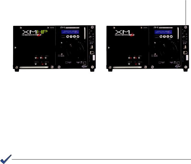
1.1Theory of Operation
The Intelligent CableUPS is comprised of the:
•Transformer module, which acts as a stand-alone line conditioner. The transformer module contains a ferroresonant transformer, resonant capacitor, transfer isolation relay,
Power Distribution Board and the optional Protective Interface Module (PIM) board.
•Inverter module, which is required for standby operations and contains circuitry needed for the three-stage temperature-compensated battery charger, DC to AC converter
(inverter), AC line detectors and Smart Display.
•Optional communications module, used to provide external status monitoring and communications.
|
|
|
DOCSIS® |
|
|
|
DOCSIS® |
|
|
Communications |
|
|
Communications |
||
High Efficiency |
|
Intelligent Inverter |
Module |
Transformer Module |
|
Intelligent Inverter |
Module |
|
|
|
|
||||
Transformer Module |
|
Module |
|
|
|
Module |
|
|
|
|
|
|
|
|
|
Fig. 1-1, XM2-HP Power Supply |
Fig. 1-2, Standard XM2 Power Supply |
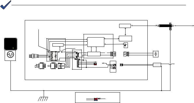
1.1.1 AC (Line) Operation
During AC Line operation, utility power is routed into the primary winding of the ferroresonant transformer through the contacts of the transfer isolation relay.
Simultaneously, in the inverter, power is directed to the rectifier circuitry providing power for the control circuitry. The bidirectional inverter also serves as a battery charger during line operation. The ferroresonant transformer and an AC capacitor form the resonant tank circuit, which provides excellent noise and spike attenuation, output short circuit current limiting and output voltage regulation. The ferroresonant transformer produces a quasi square wave output which resembles a rounded square wave.
NOTE:
When measuring the output voltage of ferroresonant transformers, use only a true RMS AC voltmeter. Non-RMS reading meters are calibrated to respond to pure sine waves and do not provide an accurate reading when measuring quasi square wave output.
017-805-B0-010 Rev. K2 |
15 |
1.1Theory of Operation, continued
1.1.2 Standby Operation
When the incoming AC line voltage drops or rises significantly or a complete power outage occurs, the control logic’s line monitor activates standby operation. During the transfer from AC line to standby operation, the battery powered inverter comes online as the isolation relay switches to prevent AC power from back-feeding to the utility. The energy contained in the ferroresonant transformer continues to supply power to
the load. The following changes also occur within the power supply:
•The isolation relay opens to disconnect the AC line from the primary winding of the ferroresonant transformer.
•The control logic drives the inverter FETs on and off at line frequency. This switching action converts the DC battery current into AC current in the inverter windings of the ferroresonant transformer, providing regulated power to the load.
•The control logic, which includes a microprocessor and other circuits to protect the inverter FETs from overcurrent damage, monitors the condition of the batteries and the inverter during standby operation. Since a prolonged AC line outage would severely discharge the batteries, resulting in permanent damage, the control logic disables the inverter when the batteries drop to approximately
10.5Vdc per battery (31.5Vdc in a three-battery set or 42.0Vdc in a four-battery set).
When acceptable AC line voltage returns, the power supply returns to AC line operation after a 20 to 40 second lag. This delay lets the AC line voltage and frequency stabilize before the control logic phase-locks the inverter’s output to the utility input. The control logic then de-energizes the isolation relay, reconnects the
AC line to the primary of the ferroresonant transformer and disables (turns off) the inverter. This results in a smooth, in-phase transfer back to utility power without interruption of service to the load. The battery charging circuit then activates to recharge the batteries in preparation for the next power outage.
NOTE:
The output fuse has been removed from models of the XM2 Power Supply manufactured after July
2006. |
|
|
|
|
|
|
|
|
|
Coaxial surge protector (Gas Filled) |
|
|
|
|
|
|
|
|
|
|
|
|
|
|
|
|
|
|
|
|
|
Transponder Overvoltage protection |
|
|
|
|
|
|
|
|
|
|
(Alpha p/n 162-028-10) |
Optional Surge Protector - |
|
|
|
|
|
|
|
|
Transponder |
Surge Protector |
|
|
|
|
|
|
|
|
|
Status Monitoring |
|
Replaceable Primary Power Supply |
Littlefuse V320LA40BP Varistors |
|
|
|
|
|
|
|
||
|
|
|
|
|
|
|
Network |
|||
Overvoltage protection |
|
|
|
|
|
|
|
|||
Secondary Power Supply Overvoltage protection |
|
Inverter Module Assembly |
|
|
|
|||||
(plugged into upper receptacle |
|
|
|
|
||||||
of parallel-wired outlet) |
|
|
|
|
|
|
|
|
|
|
|
Power Distribution Board |
|
|
|
|
|
Optional |
|
||
|
|
|
AC1 |
AC Line Detector |
|
|
Communications |
|
||
|
|
|
AC2 |
|
|
Card |
|
|||
|
|
|
and Control Logic |
|
|
|
||||
|
|
|
|
|
|
|
|
|||
|
|
Relay Control |
Control Bus |
Circuits |
|
|
|
RemoteTemperature |
|
|
|
|
|
|
|
|
|
|
|
||
|
|
|
Isolation Relay |
|
|
|
|
|
Sensor |
|
|
|
|
|
|
|
Battery Circuit |
|
Batteries |
||
|
|
K1 |
|
|
|
Breaker(+) |
Red |
Red |
|
|
|
|
RV2 |
|
Inverter |
|
|
(-) |
|
|
|
|
|
|
|
|
|
|
|
|
||
|
|
RV1 |
|
|
|
|
|
Black |
Black |
|
|
|
RV3 |
|
|
|
|
|
|
||
|
|
|
|
|
|
|
|
|
|
|
|
|
|
|
C1 |
|
|
|
|
|
Coaxial Cable Power Inserter |
|
|
|
|
|
|
|
|
|
|
|
|
|
|
|
87/89 Vac |
Black |
|
|
Output 1A |
|
(Alpha’s SPI) |
|
|
|
|
75 Vac |
White |
|
|
|
Coaxial Network |
|
|
|
|
|
63 Vac |
|
|
Black |
|
||
|
|
|
|
Red |
Black |
|
|
|||
|
|
|
|
|
|
|
|
White |
|
|
|
|
|
Transformer |
Factory-set output tap connector |
|
Black |
|
|
||
|
|
|
|
White |
|
|
||||
|
120Vac Jumper |
240Vac Jumper |
|
(settings for 48V/63V models shown below) |
|
Output 1B |
|
|
||
|
|
|
|
|
|
|
|
|
||
|
Input Select |
|
|
|
|
AC Output |
|
|
||
|
|
|
|
|
|
|
Connectors |
|
|
|
|
XM Series 2 Power Supply Chassis |
|
|
|
|
|
|
|
|
|
Output tap connector (shown in default 63Vac position)
Transformer |
63 Vac |
Red |
Black |
AC Output |
|
|
|||
48 Vac |
|
|
||
|
|
Blue |
|
|
Earth Ground (Enclosure)
Fig. 1-3, Simplified Block Diagram
16 |
017-805-B0-010 Rev. K2 |
1.1Theory of Operation, continued
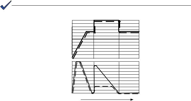
1.1.3 Charger Operation
The Intelligent CableUPS uses a three-stage, temperature-compensated battery charger. During AC line operation, the inverter winding on the ferroresonant transformer feeds the charger circuit which provides BULK, ACCEPT and FLOAT charge voltages to the batteries.
Charger Modes
BULK charge is a “Constant Current” charge. The maximum current is 10A. As the charge is returned to the batteries, their voltage increases to a specific threshold (2.27Vdc per cell). The charger then switches to ACCEPT mode. The BULK charger mode generally returns the battery charge state to 80 percent of rated battery capacity.
ACCEPT charge is a “Constant Voltage” charge. This voltage, 2.40Vdc (adjustable) per cell, is temperature-compensated to ensure longer battery life and proper completion of the charge cycle. This cycle is complete when the charging current into the batteries becomes less than 0.5A or approximately six hours elapses from the time ACCEPT mode was entered. When the batteries are fully recharged the charger switches to the FLOAT mode of operation.
FLOAT charge is a temperature-compensated “pulsed voltage” charge, averaging about 2.27Vdc (adjustable) per cell. During FLOAT mode, the batteries are
fully charged and ready to provide backup power. The charger provides a small maintenance charge to overcome the batteries self-discharge characteristics and other minor DC loads within the power supply. As the battery voltage reaches the “full charge” level the time delay between pulses increases.
During ACCEPT and FLOAT modes, the cell voltage is temperature-compensated at -0.005Vdc per cell per degree C (adjustable) to ensure a safe battery cell voltage and to maximize battery life.
NOTE:
On HP models, when Alpha Cell is the selected battery type, ACCEPT and FLOAT are pre-set and are not manually selectable.
2.40 |
2.25 |
2.15 |
Volts Per Cell |
2.05 |
10
9
8
7
6
5
4
3
2
1
0
|
Charger Current |
|
Bulk |
Accept |
Float |
Fig. 1-4, Charger Modes
(dashed lines indicate HV models)
017-805-B0-010 Rev. K2 |
17 |

1.2Intelligent CableUPS Layout
1.2.1 Transformer Module Overview
AC Output Fuse (legacy models only): Legacy XM2 power supplies use either a 20A slow blow or 30A slow blow fuse. To provide increased durability, an integrated fuse guard protects the fuse.
Output N L (legacy models only): Use the output test point (output N L) to check the AC output. Use a true RMS AC voltmeter equipped with the proper test probes; other meters may give false or inaccurate readings.
N+1 (Optional): Use the N+1 ports in redundant system configurations where multiple power supplies are housed in a single enclosure. If a power supply fails, a redundant power supply automatically switches into service (8ms delay). This feature is part of the PIM option.
LRI (Local/Remote Indicator): The LRI lamp option is used in conjunction with the automatic performance feature and plugs directly into the LRI connector. The LRI circuit is rated at 12Vdc, 250mA. This option duplicates the function of the red
ALARM LED by illuminating an externally mounted red lamp for standby operation.
Output 1A (White = Neutral, Black = Line): The AC output connector is clearly marked and color-coded for easy identification. The service power inserter (SPI) connects directly into the Output 1A connector.
Output 1B (White = Neutral, Black = Line): This output is wired in parallel to Output
1A (Output 1A +1B = Output 1) and is often used for auxiliary loads.
NOTE:
The Smart Display only displays Output 1, which is the sum of Output 1A and Output 1B.
Output 2 (Optional) [White = Neutral, Black = Line]: The AC output connector is clearly marked and color-coded for easy identification. The SPI, which couples power to the load, connects directly into the Output 2 connector. This feature is part of the PIM option.
N+1 Ports |
|
|
|
|
|
|
|
|
Output 2 |
|
LRI |
|
|
|
|
|
|
|
Output 1A |
||
|
|
|
|
|
|
|
||||
|
|
|
|
|
|
|
||||
Output 1B |
|
|
|
|
|
|
|
|
|
|
|
|
|
|
|
|
|
|
|
||
|
|
|
|
|
|
|
|
|
|
|
Fig. 1-5, Transformer Module Connections
18 |
017-805-B0-010 Rev. K2 |
1.2Intelligent CableUPS Layout, continued
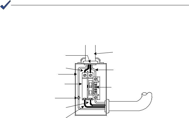
1.2.2 Inverter Module Overview
The removable inverter module provides uninterrupted power to the ferroresonant transformer (via the batteries) during line failures. During line operation, the inverter charges the batteries using a three-stage (Bulk, Accept and Float) charger.
Each inverter module and transformer module is labeled to indicate its voltage and current rating. The power supply also carries a voltage and current rating label. It is very important the inverter module is installed only in a power supply with the
same voltage and current rating. If the labels do not match, do not install the inverter module. Each unit will bear a label (examples shown below) on the inverter module and on the inside chassis floor.
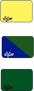
36V
953-527-10-002 F
48V
953-527-12-002 F
48VOLT
1350VA
953-527-11-002 F
Current 36V Inverter Modules bear this yellow label. This label and the label located on the interior chassis floor must
match. However, inverter modules carrying this yellow label are backward compatible with 36V power supplies manufactured prior to September 2006, which bear yellow labels. Do not install the inverter module if the voltages do not match.
Current 48V inverter modules bear this two-color label. This label and the label located on the interior chassis floor must match.
However, inverter modules carrying this blue/green label are backward compatible with all 48V power supplies manufactured prior to September 2006, which bear green labels.
Obsolete-style label for the 1350VA 48V inverter modules. The current 1350VA 48V inverter module (manufactured after
September 2006) carries a green label. If your legacy power supply carries this green voltage and current rating label, it is compatible with the latest blue/green labeled inverter module.
Fig. 1-6, Inverter Module Voltage Rating Labels
017-805-B0-010 Rev. K2 |
19 |
1.2Intelligent CableUPS Layout, continued
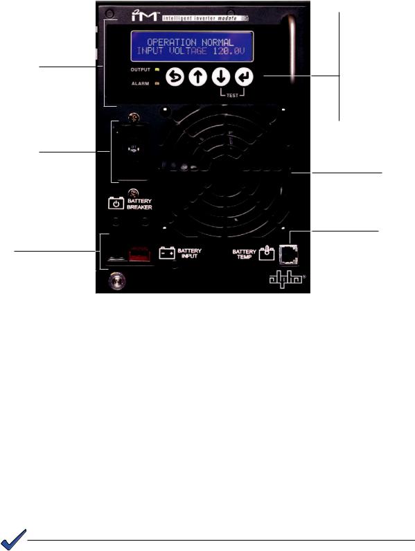
1.2.2 Inverter Module Overview, continued
Smart Display
Battery Breaker
Battery Input Connector
Fig. 1-7, Inverter Module Connections
 Escape
 Up
Up
 Down
Down
 Enter
Enter
Inverter Cooling Fan
Temperature Probe
Connector
Smart Display: All operational functions, system testing, setup items and alarms are available via the Smart Display panel on the front of the power supply (the Smart Display is covered in detail in Section 4.2). Display functions are accessible by pressing any of the four keys: ESCAPE, UP, DOWN or ENTER. Backlighting is activated when any of the four keys are pressed and stays lit for a period of one hour. There are four levels of menu items for the standard unit: Operation Normal, Additional Information, Setup and Alarms. For units equipped with DSM2 (or newer) Communications Modules the four levels are: Operation
Normal, Communication Information, Setup and Alarms. Pressing ENTER will sequence the display one level lower and pressing ESCAPE will sequence the display one level higher.
Battery Breaker: The battery breaker disconnects the batteries from the inverter module’s
DC circuit. With the battery breaker turned off, the power supply does not transfer to standby mode, the inverter is disabled and the battery charger cannot charge the batteries. The breaker trips when an overcurrent is detected in the DC circuitry or the battery polarity is accidently reversed.
Battery Input Connector: The battery cable connector plugs directly into the inverter module’s battery input connector. The connector is polarized and fits in one direction only.
NOTE:
Always verify proper polarity of cables before connecting the batteries to the power module. Reversing the battery polarity can cause permanent damage to the power supply. Polarity is clearly marked for easy identification.
20 |
017-805-B0-010 Rev. K2 |
1.2Intelligent CableUPS Layout, continued
1.2.2 Inverter Module Overview, continued
Inverter Cooling Fan: The inverter module is equipped with a cooling fan that operates during standby operation when the inverter heatsink temperature reaches 85°C. The fan stays on until the temperature drops below 75°C. The fan also operates whenever a self-test is in progress.
Temp Probe Connector: The Remote Temperature Sensor (RTS) plugs directly into the temperature probe (RJ-11C type) connector.
Batt Volt (Battery Test Point) [legacy models only]: With the battery breaker on and battery string(s) connected, DC Output can easily be checked using the inverter module’s battery test point. Use a DC voltmeter whenever checking the output.
The Remote Temperature Sensor is held in place on the AlphaCell 165, 195, 210 and 220 series batteries by a Battery Spacer Clip. To install, flex the clip and hook the retaining tabs over the top of the battery and slide the sensor into place in the clip as shown below. For domestic applications, use one battery clip per 36V battery string and two clips per 48V battery string for optimal spacing. For International applications use two clips per 36V battery string and four per 48V battery string. As an option to the Battery Spacer Clip, an RTS with ring lug can be used (p/n 746-254-XX).
Fig. 1-8, Placement of Remote Temperature Sensor (RTS) on battery
Battery Spacer Clips (Domestic applications)
|
RTS Ring |
|
|
|
RTS Ring |
|
|
Lug option |
|
|
Lug option |
|
|
|
placement |
|
|
placement |
|
|
- |
- |
- |
- |
- |
- |
- |
3 |
2 |
1 |
4 |
3 |
2 |
1 |
+ |
+ |
+ |
+ |
+ |
+ |
+ |
36V battery string |
|
48V battery string |
||||
Battery Spacer Clips (International applications)
|
RTS Ring |
|
RTS Ring |
|
|
|
|
Lug option |
|
Lug option |
|
|
|
|
placement |
|
placement |
|
|
|
- |
- |
- |
- |
- |
- |
- |
3 |
2 |
1 |
4 |
3 |
2 |
1 |
+ |
+ |
+ |
+ |
+ |
+ |
+ |
Fig. 1-9, Placement of Battery Spacer Clips on 36V and 48V battery strings
(Note: actual placement determined by battery arrangement)
017-805-B0-010 Rev. K2 |
21 |
1.2Intelligent CableUPS Layout, continued
1.2.3Optional Status Monitoring Modules
The power supply supports a number of Alpha Technologies communication modules which may be ordered factory-installed or as a user-installed field upgrade.
NOTE:
If communications options are installed, Alpha highly recommends adding the coaxial surge arrestor for the transponder (See Section 1.3, Recommended Enclosure System Options).
CAUTION!
Handle these modules with extreme care. Circuit boards and logic upgrades are static-sensitive and susceptible to damage.
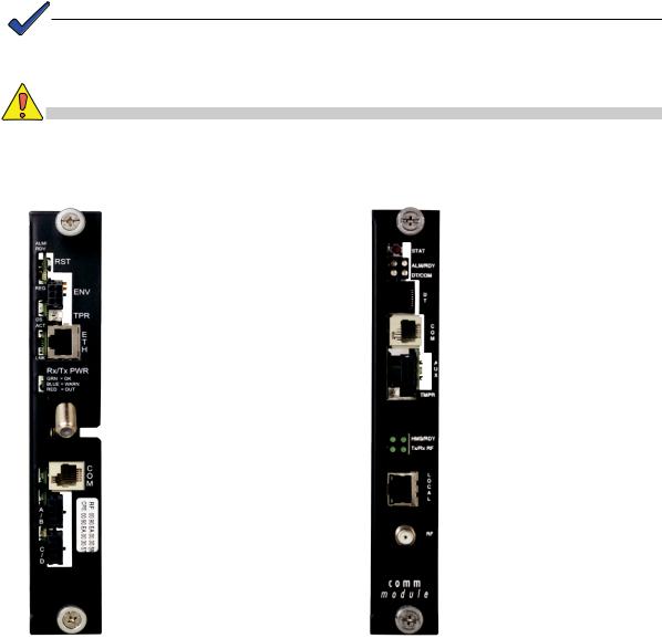
DOCSIS® Status Module 3x
The AlphaNet DSM3x Embedded
DOCSIS Transponder allows monitoring of Alpha power supplies through existing cable network infrastructure. Multiple power supplies, batteries and a generator can be monitored using a single transponder. Advanced networking services provide quick reporting and access to critical powering information.
The DSM3x utilizes Simple
Network Management
Protocol (SNMP) and standard
Management Information Bases
(MIBs) to provide network status monitoring and diagnostics. A Web interface enables authorized personnel direct access to advanced diagnostics using a common Web browser. No custom software is required.
DOCSIS® IDH3
The IDH3 Digital Embedded DOCSIS Transponder enables cable operators to manage their network powering through the existing cable modem infrastructure. Multiple power supplies, batteries and a generator can be monitored
using a single transponder. Data is transmitted to a management system over the network’s
DOCSIS cable modem channels through the existing CMTS.
Bandwidth utilization is minimized by using standard SNMP (Simple Network Management
Protocol) communications.
Status monitoring information is compatible with ANSI/SCTE HMS standards.
Fig. 1-10, DSM3x |
Fig. 1-11, IDH3 |
22 |
017-805-B0-010 Rev. K2 |
1.3Recommended Enclosure System Options
These options can be factory installed or upgraded in the field by the user:
Protective Interface Module (PIM)
The PIM protects system components by shutting down the load during overcurrent and short circuit conditions. The PIM has an operator programmable overcurrent threshold (3A-24A) and a programmable overcurrent tolerance period, which specifies the time (1-10 seconds) an overcurrent condition is permitted before the output shuts down.
Using the programmable retry limit, the operator can select how many times (0-40) after a programmable delay (5-301 seconds) the PIM will attempt to reconnect an output that has been shut down. Once the limit is reached, the power supply automatically retries once every 30 minutes until the fault clears. The PIM also provides N+1 redundancy in system configurations with programmable dual outputs.
Local and Remote Indicator (LRI)
The LRI (red) lamp is located on the outside of pole-mount enclosures. Using this simple form of status monitoring operators can check the operational status of the power supply without having to climb the pole and open the enclosure. During normal AC line operation, the LRI remains off. The LRI comes on only when the power supply is running in standby mode. Whenever a fault is detected during self-test, the LRI flashes to indicate that service is required.
AC Indicator (ACI)
The AC Indicator (green lamp) is located next to the LRI on the outside of pole-mount enclosures and also acts as a simple form of status monitoring so cable technicians can check the output status of the power supply without having to climb the pole and open the enclosure. As long as there is voltage present at the output, the ACI remains on. To provide much longer life than the original light bulb design, use the ACI-LL (long life LED). Models for
60V and 90V are available. Do not use ACIs for ground mount enclosures.
LA-P+, LA-P-120T 120V, 240V (Lightning Arrestor)
The LA-P+ plugs directly into the enclosure’s convenience outlet and provides additional protection from voltage spikes caused by lightning and other power disturbances. It eliminates the need for hard-wired MOVs. No additional wiring is necessary.
LA-P+ With Status Monitoring
Incorporates the same features as the LA-P+, with the additional benefit of Status Monitoring capability.
Co-axial Surge Arrestor
Alpha recommends using coaxial surge suppression for enclosure protection. The Coax Surge Protector (Alpha P/N 162-028-10) includes 75 ohm surge suppressor and mounting hardware.
APP90S /APP9022S (Service Power Supply)
The APP90S/APP9022S is a portable, non-standby power supply that provides conditioned AC power to the load when the main power module is out of service. An internal tap lets the APP90S/APP9022S be set for 90/75/60Vac applications. Use a 15A or 25A SPI (Service
Power Inserter) to transfer power from the APP9015S/APP9022S to the load.
017-805-B0-010 Rev. K2 |
23 |

1.3Recommended Enclosure System Options, continued
AlphaGuard™ Battery Charge Management System
The AlphaGuard Battery Charge Management System extends battery life by providing the precise voltage required for each battery. 36V (3 battery) and 48V (4 battery) versions are available. The AlphaGuard performs electrical compensation for differences in individual batteries in the string. You can configure the unit to pass measurements from the battery string to a status monitoring device, such as the EDSM card or DOCSIS transponder, using an interface cable. See the AlphaGuard System Installation Instructions, (P/N 012-306-C0), for detailed information (www. alpha.com).
Fig. 1-12, Standard AlphaGuard |
Fig. 1-13, Potted AlphaGuard |
24 |
017-805-B0-010 Rev. K2 |

2.0Installation
2.1 Installation Procedure
The Intelligent CableUPS can be shelf-mounted within a variety of Alpha enclosures. Complete the pre-installation instructions in Section 2.0 and the preliminary inspection and self-test procedure before you install the power supply.
CAUTION!
Read the Safety Precautions, Utility Power Connection Notes and Grounding Connection
Notes (pages 8-13) before you install the power supply.
Pre-installation Inspection
1.Remove the power supply from the shipping container. Confirm the power supply, including the
Remote Temperature Sensor and all other ordered options are included.
2.During shipping, components might shift. Carefully inspect the power supply and other contents for possible shipping-related failures, such as loosened or damaged connectors. If any items are damaged or missing, contact Alpha Technologies or the shipping company immediately. Most shipping companies have a short claim period.
3.Do not attempt to install a damaged power supply without first passing a complete pre-installation inspection and start-up test.
NOTE:
See the “Preliminary Inspection/Pre-Service Checklist” (Alpha P/N 017-805-B5) that accompanies each power supply. SAVE THE ORIGINAL SHIPPING CONTAINER.
Use the original shipping container if the power supply needs to be returned for service. If the original container is not available, make sure the unit is well packed with at least three inches of shockabsorbing material to prevent shipping damage.
 CAUTION!
Do not use popcorn-type material. Alpha Technologies is not responsible for damage caused by improper packaging of returned units.
017-805-B0-010 Rev. K2 |
25 |
2.2Installing the Optional Indicator Lamps
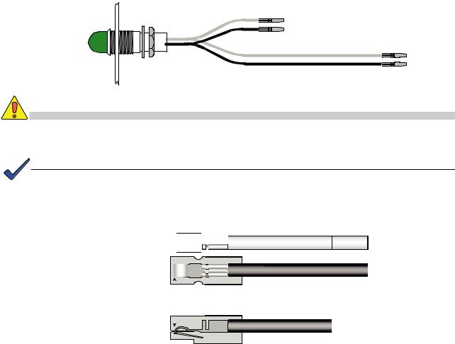
2.2.1 AC Indicator Lamp
The AC indicator (green lamp) is located on the outside of the enclosure. When lit, it indicates AC power is available at the power supply output and enables service personnel to determine the status of the power supply without having to climb the pole.
Installation Procedure:
1.Remove the rear-most knockout (see Fig. 2-5).
2.Feed ACI wires through the hole.
3.Slide locking nut over the wires and thread onto lamp body (see Fig. 2-1).
4.Insert the crimped contacts into the plastic connectors. The BLACK wire must always go into the BLACK housing. Insert the remaining wire (this may be white, yellow or blue) into the WHITE housing (see Fig. 2-2).
5.Connect the shorter BLACK/WHITE set of wires to the BLACK/WHITE wires leading from the SPI. The remaining set of longer wires connects to the Output
1A connector on the front of the power supply (Fig. 2-5).
To SPI
To Output 1A
Fig. 2-1, AC Indicator Lamp
CAUTION!
Secure the contact. If you do not properly position the contact, overheating and cable assembly failure can result.
NOTE:
To remove the wire from the plastic housing, use a small screwdriver to depress the metal retainer and slide out the wire.
Top View
White Housing 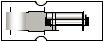 White, Yellow or Blue Wire
Black Housing |
|
|
|
|
|
|
Black Wire |
|
|
|
|
|
|
|
|
||||
|
|
|
|
|
|
||||
|
|
|
|
|
|
|
|
|
|
Verify contact snaps |
|
|
|
|
Side View |
|
|||
over metal retainer |
|
|
|
|
|
||||
|
|
|
|
|
|
|
|
|
|
|
|
|
|
|
|
|
|
|
|
|
|
|
|
|
|
|
|
|
|
|
|
|
|
|
|
|
|
|
|
|
|
|
|
|
|
|
|
|
|
|
|
|
|
|
|
|
|
|
|
Fig. 2-2, Wire/Housing Assembly
26 |
017-805-B0-010 Rev. K2 |
2.2Installing the Optional Indicator Lamps, continued
2.2.2 Local/Remote Indicator
The Local/Remote indicator (Red lamp) is located on the outside of the enclosure.
During normal AC operation, the lamp remains OFF. The lamp comes ON only when the power supply is running in Standby Mode. In the event a major alarm is detected, the lamp flashes to indicate service is required. The LRI is a simple form of status monitoring which allows the operational status of the power supply to be verified from the ground.
Installation Procedure:
1.Remove the front-most knockout (see Fig. 2-5).
2.Feed LRI wires through the hole.
3.Slide locking nut over the wires and thread onto lamp body (see Fig. 2-3).
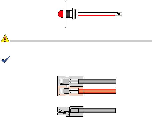
4.Insert the crimped contacts into the plastic connectors. The BLACK wire must always go into the BLACK housing and the RED wire into the RED housing (see
Fig. 2-4).
5.Connect the wire harness into the LRI connector on the front panel of the power supply.
Fig. 2-3, Local/Remote Indicator Lamp
CAUTION!
Secure the contact. If you do not properly position the contact, overheating and cable assembly failure can result.
NOTE:
To remove the wire from the plastic housing, use a small screwdriver to depress the metal retainer and slide out the wire.
|
Top View |
|
Black Housing |
Black Wire |
|
Red Housing |
Red Wire |
|
Verify contact snaps |
Side View |
|
over metal retainer |
||
|
Fig. 2-4, Wire/Housing Assembly
017-805-B0-010 Rev. K2 |
27 |
 Loading...