


Allied Telesis XEM-12S, XEM-24T, XEM-2XP, XEM-12SV2, XEM-12TV2 User Manual
...
x900 Series Switch and SwitchBlade® x908 |
Expansion Module |
Installation Guide |
XEM-1XP |
XEM-2XP |
XEM-2XS |
XEM-12S |
XEM-12Sv2 |
XEM-12T |
XEM-12Tv2 |
XEM-2XT |
XEM-24T |
XEM-STK
Expansion Modules
x900 Series Switch and SwitchBlade® x908 Expansion Module Installation Guide Document Number 613-000032 REV N
© 2005-2012 Allied Telesis, Inc. All rights reserved. No part of this publication may be reproduced without prior written permission from Allied Telesis, Inc.
Allied Telesis, Inc. reserves the right to change specifications and other information in this document without prior written notice. The information provided herein is subject to change without notice. In no event shall Allied Telesis, Inc. be liable for any incidental, special, indirect, or consequential damages whatsoever, including but not limited to lost profits, arising out of or related to this manual or the information contained herein, even if Allied Telesis, Inc. has been advised of, known, or should have known, the possibility of such damages.
Allied Telesis, AlliedWare, AlliedWare Plus, and SwitchBlade are trademarks or registered trademarks in the United States and elsewhere of Allied Telesis, Inc. Adobe, Acrobat, and Reader are either registered trademarks or trademarks of Adobe Systems Incorporated in the United States and/or other countries.
Microsoft and Visio are either registered trademarks or trademarks of Microsoft Corporation in the United States and/or other countries. Additional brands, names and products mentioned herein may be trademarks of their respective companies.
2

|
Installation Guide |
Contents |
|
About this Guide .............................................................................................................. |
4 |
Compatible Switches and Operating Systems ........................................................... |
5 |
Compatible Pluggable Optical Modules ....................................................................... |
6 |
Package Contents ............................................................................................................. |
6 |
XEM-1XP 10Gigabit XFP Port ...................................................................................... |
7 |
XEM-2XP Dual 10Gigabit XFP Ports .......................................................................... |
9 |
XEM-2XS Dual 10Gigabit SFP+ Ports ....................................................................... |
11 |
XEM-12S 100/1000BASE-X SFP Ports ...................................................................... |
13 |
XEM-12Sv2 100/1000BASE-X SFP Ports .................................................................. |
15 |
XEM-12T 10/100/1000BASE-T RJ-45 Ports ............................................................. |
17 |
XEM-12Tv2 10/100/1000BASE-T RJ-45 Ports ........................................................ |
19 |
XEM-2XT Dual 10GBASE-T RJ-45 Ports ................................................................. |
21 |
XEM-24T 24 Tri-speed Gigabit Copper Ports ......................................................... |
22 |
XEM-STK Stacking Ports .............................................................................................. |
24 |
Installation Procedure .................................................................................................... |
26 |
Obtaining Documentation and Resources ............................................................... |
30 |
3

Expansion Modules
About this Guide
Optional expansion modules (XEMs) enable economical combinations of port type, speed and density in a single switch. Front bays in the switch allow quick and easy installation.
This Installation Guide describes how to install the following XEMs:
■XEM-1XP, a single XFP port for high-speed fibre connections
■XEM-2XP, a dual 10 GbE XFP port expansion module for high-speed fibre connections
■XEM-2XS, a dual 10 GbE SFP+ port expansion module for high-speed fibre and SFP+ Direct Attach copper connections
■XEM-12S, 12 SFP ports for copper and fibre links
■XEM-12Sv2, 12 SFP ports for copper and fibre links
■XEM-12T, 12 x 10/100/1000 Mbps RJ-45 ports
■XEM-12Tv2, 12 x 10/100/1000 Mbps RJ-45 ports
■XEM-2XT, a dual 10 GbE RJ-45 port expansion module for high-speed copper connections
■XEM-24T, 24 x RJ Point Five ports for high density cabling solutions
■XEM-STK, dual stacking ports for scalability and high availability
You can download the complete document set for x900 Series switches and SwitchBlade® x908 from www.alliedtelesis.com/support/software. For more information about the document set and other resources, see “Obtaining Documentation and Resources” on page 30.
4

Installation Guide
Compatible Switches and Operating Systems
XEMs can be installed in the following switches:
■x900-12XT/S
■x900-24XT
■x900-24XT-N
■x900-24XS
■SwitchBlade x908
The SwitchBlade x908 can operate in Extended Mode to take advantage of larger table sizes and Link Aggregation Groups, as shown in the following table:
|
Standard Mode |
Extended Mode |
|
|
|
MAC entries |
16K |
32K |
|
|
|
LAGs |
31 |
128 |
|
|
|
Extended Mode can be enabled when the following XEMs are installed in a SwitchBlade x908 switch:
■XEM-2XP
■XEM-2XS
■XEM-12Sv2
■XEM-12Tv2
■XEM-2XT
■XEM-24T
The AlliedWare Plus™ Operating System supports all XEMs. The AlliedWare® Operating System supports all XEMs except the XEM-STK, the XEM-2XP and the XEM-2XT.
5

Expansion Modules
Compatible Pluggable Optical Modules
For the latest list of approved SFP, SFP+ and XFP fibre transceivers plus SFP+ Direct Attach copper modules, contact your authorised Allied Telesis distributor or reseller. See the most current revision available of the XEM datasheet (document number 617-000034) for further information about which SFP, SFP+, and XFP fibre transceivers and SFP+ Direct Attach copper modules are approved for use.
Package Contents
The following items are included with each XEM:
■this Installation Guide
■one warranty card
Contact your authorised Allied Telesis distributor or reseller if any items are damaged or missing.
6
Installation Guide
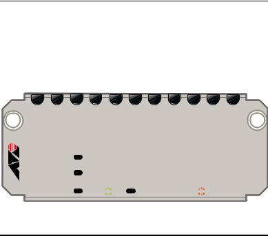
XEM-1XP 10Gigabit XFP Port
The XEM-1XP single-port 10Gigabit Ethernet expansion module features:
■one XFP port
■LEDs showing port status
■support for hot-swappable XFP transceiver modules
Front view XEM-1XP
L/A
XFP
L/A  LINK
LINK 
 ACT XFP
  ENABLED
  DISABLED
 FAULT
FAULT
XEM-1XP
The following LEDs report operations and faults on the XEM-1XP.
LED |
State |
Description |
|
|
|
L/A |
Green |
An XFP transceiver module is installed and a 10Gb |
(Link Activity) |
|
link has been established. |
|
|
|
|
Green |
An XFP transceiver module is installed and link |
|
flashing |
activity is occurring. |
|
|
|
|
Off |
A link has not been established. |
|
|
|
XFP |
Green |
An XFP transceiver module is installed and enabled. |
|
|
|
|
Amber |
An XFP transceiver module is installed but not |
|
|
operating or is disabled. |
|
|
|
|
Amber |
The installed XFP transceiver module has a fault. |
|
flashing |
|
|
|
|
|
Off |
An XFP transceiver module is not installed. |
|
|
|
7

Expansion Modules
For the latest list of approved XFP transceiver modules, contact your authorised Allied Telesis distributor or reseller. See the most current revision available of the XEM datasheet (document number 617-000034) for further information about which XFP transceiver modules are approved for use with the XEM-1XP.
Caution Allied Telesis recommends waiting 30 seconds after hot swapping any XEM before resuming normal operations. The switch must fully complete the bootup process before you can hot swap any XEM. Also ensure the XEM fastening thumbscrews are fully tightened. If you are unsure about correct procedures, contact your authorised Allied Telesis distributor or reseller.
8
Installation Guide
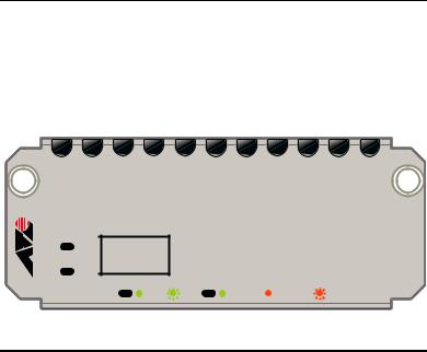
XEM-2XP Dual 10Gigabit XFP Ports
The XEM-2XP Dual 10Gigabit Ethernet expansion module features:
■two XFP ports
■four LEDs (one set for each XFP port) showing port status
■support for hot-swappable XFP transceiver modules
Front view XEM-2XP
|
1 |
|
|
|
2 |
L/A |
|
|
L/A |
|
|
XFP |
|
|
XFP |
|
|
L/A |
LINK |
ACT XFP |
ENABLED |
DISABLED |
FAULT |
XEM-2XP
The following LEDs report operations and faults on the XEM-2XP.
LED |
State |
Description |
|
|
|
L/A |
Green |
An XFP transceiver module is installed and a 10 |
(Link Activity) |
|
Gbps link has been established. |
|
|
|
|
Green |
An XFP transceiver module is installed and link |
|
flashing |
activity is occurring. |
|
|
|
|
Off |
A link has not been established. |
|
|
|
XFP |
Green |
An XFP transceiver module is installed and enabled. |
|
|
|
|
Amber |
An XFP transceiver module is installed but not |
|
|
operating or is disabled. |
|
|
|
|
Amber |
The installed XFP transceiver module is not ready |
|
flashing |
or has a fault. |
|
|
|
|
Off |
An XFP transceiver module is not installed. |
|
|
|
9

Expansion Modules
For the latest list of approved XFP transceiver modules, contact your authorised Allied Telesis distributor or reseller. See the most current revision available of the XEM datasheet (document number 617-000034) for further information about which XFP transceiver modules are approved for use with the XEM-2XP.
Caution Allied Telesis recommends waiting 30 seconds after hot swapping any XEM before resuming normal operations. The switch must fully complete the bootup process before you can hot swap any XEM. Also ensure the XEM fastening thumbscrews are fully tightened. If you are unsure about correct procedures, contact your authorised Allied Telesis distributor or reseller.
10
 Loading...