


 Loading...
AT-8000GS Series
Stackable Gigabit
Ethernet Switches
AT-8000GS/24
AT-8000GS/POE
AT-8000GS/48
Installation Guide
613-000974 Rev. B
Copyright © 2008 Allied Telesis, Inc.
All rights reserved. No part of this publication may be reproduced without prior written permission from Allied Telesis, Inc.
Allied Telesis is a trademark of Allied Telesis, Inc. Microsoft and Internet Explorer are registered trademarks of Microsoft Corporation. Netscape Navigator is a registered trademark of Netscape Communications Corporation. All other product names, company names, logos or other designations mentioned herein are trademarks or registered trademarks of their respective owners.
Allied Telesis, Inc. reserves the right to make changes in specifications and other information contained in this document without prior written notice. The information provided herein is subject to change without notice. In no event shall Allied Telesis, Inc. be liable for any incidental, special, indirect, or consequential damages whatsoever, including but not limited to lost profits, arising out of or related to this manual or the information contained herein, even if Allied Telesis, Inc. has been advised of, known, or should have known, the possibility of such damages.

AT-8000GS Series Gigabit Ethernet Switch Installation Guide
Preface
This guide provides the hardware installation instructions for your managed, AT-8000GS Series Gigabit Ethernet switch. This preface contains the following sections:
“Safety Symbols Used in this Document” on page 4
“Where to Find Web-based Guides” on page 5
“Contacting Allied Telesis” on page 6
3

Preface
Safety Symbols Used in this Document
This document uses the safety symbols defined in Table 1.
|
|
|
|
Table 1. Safety Symbols |
|
|
|
|
|
Symbol |
Meaning |
Description |
||
|
|
|
|
|
|
|
|
|
|
|
|
|
Caution |
Performing or omitting a specific action may |
|
|
|
||
|
|
|
|
result in equipment damage or loss of data. |
|
|
|
|
|
|
|
|
Warning |
Performing or omitting a specific action may |
|
|
|
||
|
|
|
|
result in electrical shock. |
|
|
|
|
|
4

AT-8000GS Series Gigabit Ethernet Switch Installation Guide
Where to Find Web-based Guides
The installation and user guides for all Allied Telesis products are available in portable document format (PDF) on our web site at www.alliedtelesis.com. You can view the documents online or download them onto a local workstation or server.
5

Preface
Contacting Allied Telesis
Online Support
Email and
Telephone
Support
Returning
Products
For Sales or
Corporate
Information
Warranty
Management
Software Updates
This section provides Allied Telesis contact information for technical support as well as sales or corporate information.
You can request technical support online by accessing the Allied Telesis Knowledge Base: www.alliedtelesis.com/support/kb.aspx. You can use the Knowledge Base to submit questions to our technical support staff and review answers to previously asked questions.
For Technical Support via email or telephone, refer to the Support section of the Allied Telesis web site: www.alliedtelesis.com/support.
Products for return or repair must first be assigned a return materials authorization (RMA) number. A product sent to Allied Telesis without an RMA number will be returned to the sender at the sender’s expense. For instructions on how to obtain an RMA number, go to the Support section on our web site at www.alliedtelesis.com/support/rma.aspx.
You can contact Allied Telesis for sales or corporate information through our web site at http://www.alliedtelesis.com/purchase.
This section provides Allied Telesis contact information for technical support as well as sales or corporate information.
The AT-8000GS Series Gigabit Ethernet Switches have a Lifetime Warranty (two years fan and PSU). Go to www.alliedtelesis.com/ warranty for the specific terms and conditions of the warranty and for warranty registration.
New releases of management software for our managed products are available from either of the following Internet sites:
Allied Telesis web site: www.alliedtelesis.com
Allied Telesis FTP server: ftp://ftp.alliedtelesis.com
If you prefer to download new software from the Allied Telesis FTP server from your workstation’s command prompt, you will need FTP client software and you must log in to the server. Enter “anonymous” for the user name and your email address for the password.
6

Content
Preface .................................................................................................................................................................................. |
3 |
Safety Symbols Used in this Document.................................................................................................................................. |
4 |
Where to Find Web-based Guides ......................................................................................................................................... |
5 |
Contacting Allied Telesis ........................................................................................................................................................ |
6 |
Online Support ................................................................................................................................................................ |
6 |
Email and Telephone Support......................................................................................................................................... |
6 |
Returning Products.......................................................................................................................................................... |
6 |
For Sales or Corporate Information................................................................................................................................. |
6 |
Warranty.......................................................................................................................................................................... |
6 |
Management Software Updates...................................................................................................................................... |
6 |
Content ................................................................................................................................................................................. |
7 |
Chapter 1: Overview ............................................................................................................................................................ |
9 |
AT-8000GS Switch Series Features..................................................................................................................................... |
10 |
IEEE Standards .................................................................................................................................................................... |
11 |
Model Descriptions ............................................................................................................................................................... |
12 |
AT-8000GS/24 .............................................................................................................................................................. |
12 |
AT-8000GS/24POE....................................................................................................................................................... |
13 |
AT-8000GS/48 .............................................................................................................................................................. |
14 |
Port Descriptions .................................................................................................................................................................. |
15 |
10/100/1000 Base-T Gigabit Ethernet Ports ................................................................................................................. |
15 |
SFP Port........................................................................................................................................................................ |
15 |
RJ-45 Console Port ....................................................................................................................................................... |
15 |
LED Definitions..................................................................................................................................................................... |
16 |
System LEDS ................................................................................................................................................................ |
16 |
Stacking Port LEDs ....................................................................................................................................................... |
17 |
Mode LEDs.................................................................................................................................................................... |
18 |
RJ-45 Port LEDs on AT-8000GS/24 & AT-8000GS/48 ................................................................................................. |
19 |
RJ-45 Port LEDs AT-8000GS/24POE........................................................................................................................... |
21 |
SFP Port LEDs .............................................................................................................................................................. |
22 |
Stacking Port LEDs ....................................................................................................................................................... |
23 |
Chapter 2: Installation ....................................................................................................................................................... |
25 |
Reviewing Safety Precautions.............................................................................................................................................. |
26 |
Preparing for Installation....................................................................................................................................................... |
29 |
Installation Precautions ................................................................................................................................................. |
29 |
Site Requirements......................................................................................................................................................... |
30 |
Unpacking ..................................................................................................................................................................... |
30 |
Installing the Device ............................................................................................................................................................. |
32 |
Desktop or Shelf Installation.......................................................................................................................................... |
32 |
Rack Installation ............................................................................................................................................................ |
32 |
Connecting the Device ......................................................................................................................................................... |
34 |
Connecting the Switch to a Terminal............................................................................................................................. |
34 |
AC Power Connection ................................................................................................................................................... |
34 |
7
Contents |
|
Chapter 3: Stacking ........................................................................................................................................................... |
35 |
Stacking Overview ................................................................................................................................................................ |
36 |
Stacking Ring Topology................................................................................................................................................. |
36 |
Stacking Chain Topology............................................................................................................................................... |
37 |
Stacking Members and Unit ID...................................................................................................................................... |
37 |
Removing and Replacing Stacking Members................................................................................................................ |
37 |
Exchanging Stacking Members ..................................................................................................................................... |
39 |
Configuring Stacking............................................................................................................................................................. |
40 |
Chapter 4: Initial Configuration ........................................................................................................................................ |
43 |
Configuration Overview......................................................................................................................................................... |
44 |
Configuration ........................................................................................................................................................................ |
45 |
Static IP Address and Subnet Mask .............................................................................................................................. |
45 |
User Name .................................................................................................................................................................... |
46 |
Chapter 5: Troubleshooting .............................................................................................................................................. |
47 |
Device not operating correctly ....................................................................................................................................... |
47 |
Cannot connect using Telnet, Web browser, or SNMP software................................................................................... |
47 |
Forgot or lost the password ........................................................................................................................................... |
48 |
Appendix A: Technical Specifications ............................................................................................................................. |
49 |
Physical Specifications ......................................................................................................................................................... |
49 |
Weight................................................................................................................................................................................... |
49 |
Environmental Specifications................................................................................................................................................ |
49 |
Power Specifications............................................................................................................................................................. |
50 |
Certifications ......................................................................................................................................................................... |
50 |
Cable, Port, and Pinout Information...................................................................................................................................... |
50 |
Pin Connections for the 10/100/1000 Ethernet Interface...................................................................................................... |
51 |
8

Chapter 1
Overview
This chapter contains the following sections:
“AT-8000GS Switch Series Features” on page 10
“IEEE Standards” on page 11
“Model Descriptions” on page 12
“Port Descriptions” on page 15
“LED Definitions” on page 16
The AT-8000GS Gigabit Ethernet Switch series includes three device models, which consist of the following hardware configurations:
AT-8000GS/24 Gigabit Ethernet Switch with 24 10/100/1000 Base-T ports with 4 1000Base-X SFP combo ports and 2 HDMI interface stacking ports.
AT-8000GS/24POE Gigabit Ethernet Switch with 24 10/100/1000 Base-T ports ports with modular configuration 4 x 1000Base-X SFP Combo ports and 2 HDMI interface stacking ports and support for 802.3af Power over Ethernet on the RJ-45 ports. The total POE power available is 140W which allows for a maximum of nine class 3 devices (15.4W per device) or a dynamic distribution of power across any or all 24 ports based on user-assigned priorities.
AT-8000GS/24POE Gigabit Ethernet Switch with 48 10/100/1000 Base-T ports with modular configuration 4 x combo 1000Base-X SFP Combo ports and 2 HDMI interface stacking ports.
All the platforms can operate as standalone systems, or can be stacked together in the same system. A stack of six units maximum is supported.
In each stack, at any given point of time, there is a single Stack unit that is the stack’s “Master”; all other units are “Slaves”. One of the slaves can act as a backup master, so that in the event of failure of the master unit, the backup takes over. The Stack architecture provides for dynamic learning of the topology, and dynamic detection at stack start-up.
Device configuration is performed through an Embedded Web Server (EWS) or through a Command Line interface (CLI). The device management is performed through an RS-232 interface.
9

Chapter 1: Overview
AT-8000GS Switch Series Features
The AT-8000GS/24, AT-8000GS/24POE, and AT-8000GS/48 features include the following:
Wire speed switching traffic across all ports
Auto MDI/MDIX enabled
Jumbo frames
802.1d, 1w, 1s priority tags supported
Broadcast storm control
IEEE 802.1Q tagged VLANs supported
GARP/GVRP supported
Port/MAC based VLANs supported
802.3ad link aggregation Static and Dynamic (LACP) supported
IEEE 802.1P based QoS supported
Ingress rate limiting
Egress rate shaping (WRR)
802.1x port/MAC based authentication support
RFC 2618 RADIUS Authentication
SSL/ SSLv3
RFC 1492 TACACS+
Management ACL support
Industry standard CLI
Browser based management interface (HTTP)
Telnet access supported
SNMP v1, v2 and v3
RFC1757 RMON support
Port Mirroring support
PVE
Port Security
DHCP support
Static IP Multicast support
IGMP Snooping
10
AT-8000GS Series Gigabit Ethernet Switch Installation Guide
IEEE Standards
IEEE 802.3 — 10Base-T
IEEE 802.3u — 100Base-TX
IEEE 802.3ab — 1000Base-TX Gigabit Ethernet
IEEE 802.3z — Full Duplex
IEEE 802.3u — Auto-Negotiation
IEEE 802.3x — Flow Control, Symmetric and Asymmetric
11

Chapter 1: Overview
Model Descriptions
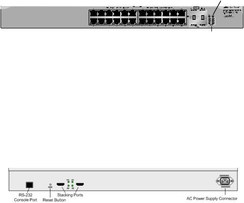
AT-8000GS/24 The following figure illustrates the AT-8000GS/24 front panel.
Figure 1 AT-8000GS/24 Gigabit Ethernet Switch Front Panel
|
|
|
|
|
|
|
Power |
Diagnostic |
|||
10/100/1000Base-T Ports |
SFP |
Ports LED |
|
LED |
|||||||
|
|
||||||||||
|
|
|
|
|
|
|
|
|
|
|
|
|
|
|
|
|
|
|
|
|
|
|
|
|
|
|
|
|
|
|
|
|
|
|
|
|
|
|
|
|
|
|
|
|
|
|
|
|
|
|
|
|
|
|
|
|
|
|
|
|
|
|
|
|
|
|
|
|
|
|
|
|
|
|
|
|
|
|
|
|
|
|
|
1336
Stacking Mode Mode LEDs LEDs Button
The AT-8000GS/24 front panel is configured as follows:
24 10/100/1000Mbps ports — RJ-45 ports designated as 10/100/ 1000Base-T. The RJ-45 ports are designated as Ports 1-24.
4 SFP Ports — There are four 1000Base-X SFP combo ports. These ports are associated with the RJ-45 copper ports: 21, 22, 23 and 24.
Select Button — Selects the port LED indications.
The following figure illustrates the AT-8000GS/24 back panel.
Figure 2 AT-8000GS/24 Gigabit Ethernet Switch Back Panel
The AT-8000GS/24 back panel is configured as follows:
Power Connector — AC power supply interface.
2 Stacking Ports — Two HDMI connector stacking ports .
Console Port — An RJ-45 connector supporting the RS-232 electrical specification.
Reset Button — Button to reset the device.
12
AT-8000GS/ 24POE
AT-8000GS Series Gigabit Ethernet Switch Installation Guide
The following figure illustrates the AT-8000GS/24POE front panel. AT-8000GS/24POE Gigabit Ethernet Switch Front Panel
|
|
|
SFP Ports |
Power |
Diagnostic |
||||||
10/100/1000Base-T Ports |
LED |
LED |
|||||||||
|
|
|
|
|
|
|
|
|
|
|
|
|
|
|
|
|
|
|
|
|
|
|
|
|
|
|
|
|
|
|
|
|
|
|
|
|
|
|
|
|
|
|
|
|
|
|
|
|
|
|
|
|
|
|
|
|
|
|
|
|
|
|
|
|
|
|
|
|
|
|
|
|
|
|
|
|
|
|
|
|
|
|
|
|
|
|
|
|
|
|
|
|
|
|
|
|
|
|
|
|
|
|
|
|
|
|
|
1337
Stacking
LEDs
The AT-8000GS/24POE front panel is configured as follows:
24 10/100/1000Mbps ports — RJ-45 ports designated as 10/100/ 1000Base-T. The RJ-45 ports are designated as Ports 1-24.
4 SFP Ports — There are four 1000Base-X SFP combo ports. These ports are associated with the RJ-45 copper ports: 21, 22, 23 and 24.
The following figure illustrates the AT-8000GS/24POE back panel. AT-8000GS/24POE Gigabit Ethernet Switch Back Panel
The AT-8000GS/24POE device back panel is configured as follows:
Power Connector — AC power supply interface.
2 Stacking Ports — Two HDMI connector stacking ports .
Console Port — An RJ-45 connector supporting the RS-232 electrical specification.
Reset Button — Button to reset the device.
13
Chapter 1: Overview
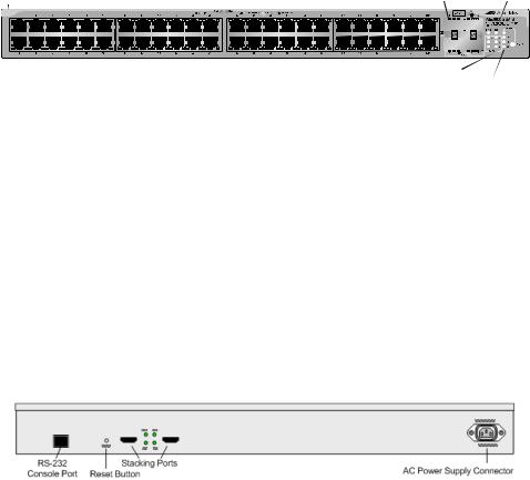
AT-8000GS/48 The following figure illustrates the AT-8000GS/48 front panel.
Figure 5 AT-8000GS/48 Gigabit Ethernet Switch Front Panel
10/100/1000Base-T Ports |
|
|
|
|
Power |
Diagnostic |
||||
SFP Ports LED |
|
LED |
||||||||
|
|
|
|
|
|
|
|
|
|
|
|
|
|
|
|
|
|
|
|
|
|
|
|
|
|
|
|
|
|
|
|
|
|
|
|
|
|
|
|
|
|
|
|
|
|
|
|
|
|
|
|
|
|
|
|
|
|
|
|
|
|
|
|
|
|
|
|
|
|
|
|
|
|
|
|
|
Stacking |
1338 |
Mode |
|
LEDs |
Mode Button |
|
LEDs |
The AT-8000GS/48 device front panel is configured as follows:
48 10/100/1000 Mbps ports — RJ-45 ports designated as 10/100/ 1000Mbps Base-T. The RJ-45 ports are designated as Ports 1-48.
4 SFP Ports — There are four 1000Base-X SFP combo ports. These ports are associated with the RJ-45 copper ports: 45, 46, 47, and 48.
Select Button — Selects the port LED indications.
The following figure illustrates the AT-8000GS/48 back panel.
Figure 6 AT-8000GS/48 Gigabit Ethernet Switch Back Panel
The AT-8000GS/48 back panel is configured as follows:
Power Connector — AC power supply interface.
2 Stacking Ports — Two HDMI connector stacking ports .
Console Port — An RJ-45 connector supporting the RS-232 electrical specification.
Reset Button — Button to reset the device.
14

AT-8000GS Series Gigabit Ethernet Switch Installation Guide
Port Descriptions
10/100/1000 Base-
T Gigabit
Ethernet Ports
SFP Port
RJ-45 Console
Port
The 10/100/1000Base-T Gigabit ports are RJ-45 ethernet connectors. The 10/100/1000 Mbps ports support halfand full-duplex mode.
Small Form Factor Pluggable (SFP) Optical Transceivers are integrated duplex data links for bi-directional communication over optical fiber, designed for high-speed Fiber Channel data links. The SFP port is designated as 100Base-FX or 1000Base-LX/SX.
Table 1 lists the supported SFPs:
|
Table 1 SFP Support |
|
|
ATI Reference |
Vendors and Parts |
|
|
|
|
AT-SPSX |
500m 850nm 1000Base-SX Small Form Pluggable - |
|
Hot Swappable |
|
|
AT-SPLX10 |
10km 1310nm 1000Base-LX Small Form Pluggable |
|
- Hot Swappable |
|
|
AT-SPLX40 |
40km 1310nm 1000Base-LX Small Form Pluggable |
|
- Hot Swappable |
|
|
AT-SPZX80 |
80km 1550nm 1000Base-ZX Small Form Pluggable |
|
- Hot Swappable |
|
|
AT-SPBD10-13 |
10km Bi-Directional GbE SMF SFP 1310Tx/1490Rx |
|
- Hot Swappable |
|
|
AT-SPBD10-14 |
10km Bi-Directional GbE SMF SFP 1490Tx/1310Rx |
|
- Hot Swappable |
|
|
The RJ-45 port on the rear panel is an asynchronous serial console port supporting the RS-232 electrical specification. The port is used to connect the device to a console managing the device. This interface configuration is as follows:
Eight data bits.
One stop bit.
No parity.
Baud rate is 115,200 (default). The user can change the rate from 115,200 down to 2400 bps.
15
Chapter 1: Overview
LED Definitions
The switch has Light Emitting Diodes (LED) on both the front and rear panels that indicate the both the port status and the switch status. The different LED types are as follows:
“System LEDS” on page 16 — These LEDs indicate the switch power supply and diagnostic result status and are are found on the front panel.
“Stacking Port LEDs” on page 17 — These LEDs indicates the switch location in a stack and are found on the front panel.
“Mode LEDs” on page 18 — These LEDs indicates the functional information that the RJ-45 port LED displays. These LEDs are only found on front panels of the AT-8000GS/24 Gigabit Ethernet Switch and AT-8000GS/48 Gigabit Ethernet Switch.
Port LEDs — These LEDs indicate each port’s status. There are different types of port LEDs which are described in the following sections:
–“RJ-45 Port LEDs on AT-8000GS/24 & AT-8000GS/ 48” on page 19.
–“RJ-45 Port LEDs AT-8000GS/24POE” on page 21
–“SFP Port LEDs” on page 22
–“Stacking Port LEDs” on page 23
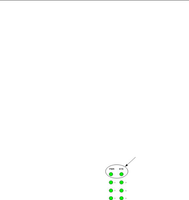
System LEDS There are two system LEDs, the Power LED and SYS LED as shown in the following figure:
Figure 7 System LEDs
16
Loading...